WK4DS Amateur Radio Blog
Search Posts
Activating K-2169 and some notes about radials and SWR that I saw today...
Ok. Radials
Today saw the use of the sBitx v2 again as I wanted to work some FT8 as well as CW. I setup at the frisbee golf parking lot on top of the hill and decide to measure the SWR plot as well as check to see the Smith plot as well of the ham stick antenna and add counter poise wires till it quit making it better. I did this because I received a comment from a ham asking about any info I might have onthis subject since he is wanting to pick up a ham stick and mess around with it.

In the above photo, we have the ham stick on the receiver hitch mount that elevates the radiator to about 6’ to the bottom of the antenna. The antenna is only wired to the cab of the truck with a 15’ piece of coax and it terminates into the nanoVNA through a common mode choke. At this point I had not turned on the 2nd trace to see the smith chart…sorry about that. In all fairness, this could be used on the air with practically no worries, I would probably turn the power down to prevent heating of the finals from the SWR, but that is me being cautious. This is completely usable to be honest.

In the above image I have added a single, approximately 15’, radial and ran it straight out away from the back of the truck. This is completely usable and I have had great activations with just this one counter poise wire. Dropping from 1.574:1 down to 1.226:1 doesn’t sound like much but it really is when you are working towards a resonant antenna. Also notice how the null point is climbing in frequency as the radial field grows under the antenna.

In this photo we see the SWR plot has gotten spectacular! I added the tuned radials for the 17m antenna to the one radial I already had installed so now I am using three radials with the antenna and look at that plot. I arranged them 90 degrees apart as this also matters. The more this angle changes the more the SWR changes too. Sometimes for the better, sometimes for the worse. Notice how it raised the frequency of resonance as I added counter poise wires to the system and it lowered the SWR to 1.028:1 as well as made the antenna slightly inductive instead of capacitive. This shows that the radials are more than simply a ground path but rather part of the tuned circuit that matches the radios transmit frequency and improved that whole system. If you have the space and time, I highly recommend adding counterpoise wires to your system and measuring it with something like a nanoVNA.

Another thing I learned is that I get best performance when the wires are pulled snug as you see in the photo above. I think this might have something to do with when I originally set it all up, I tuned them with them under tension like this which makes the wires the longest and also this changes the capacitance and inductance of the radial from just being thrown on the ground. As a matter of fact, it was when I tensioned the radial shown above that the SWR plot bottomed out like you see. It was the last one to be tightened and it made a huge difference.

By parking in this location I am able to get the radial at almost a 45 degree angle to the antenna or very near it. This matters as it is the point in the radiation pattern where to get a 50 ohm impedance match to the coax feeding it. There is tons of information out there on how to adjust the impedance of the antenna by adjust the angle of the radials…it is like some sort of dark magic to be honest.

I got on the air and started on 15 meters as it looked promising today with the noise floor being good and FT8 being quite active. As you can see though it took me quite some time to get just 6 QSOs in the log. After I worked N7ZLD I went over 20 minutes without a single call, that was when I decided to jump on FT8 to see if I could get a few in the log like that. It was slow going, but that it the fault of the radio software more than band conditions so I was happy to get 4 FT8 QSOs in the log, securing the activation only on 15 meters for a change!


After playing on 15 meters for a while I decided to see what 20 meters sounded like (I didn’t even check the antenna, I just plugged it in and got on with the activation). I quickly found myself in a small pileup working through several call and the calls kept coming in for a good while one after the other and sometimes two at once. This is the pace I really like as I don’t feel like I am missing anyone that wants the park I am at. After a great run on 20 meters CW I once again switched over to FT8 to see if I could get a few there. It took me a while to get someone on the hook, but I did work 5 more and the last one was W0NKA!!! That is (W -zero- NKA) and he is awesome, go look him up on QRZ and see about the special event he is having in December where you can get the golden ticket!
All in all it was a wonderful activation and I hope you enjoyed following along today, until next time I hope to hear you on the air.
72
WK4DS
So I have had this nagging thought about toroids.
I have wondered if the hype about certain “mixes” of core materials made THAT much of a difference in things like common mode chokes and such.
FT240-43 Ferrite Core
Well, it turns out, yes…it matters alot. Like more than you could imagine kinds of alot. Let me share my experiment numbers with you.

T130-2 Powdered Iron Core
So to do this test, I used my nanoVNA and the S21 input set to LOGMAG so I can measure the difference between port 0 and port 1 in dB. I also swept the entire HF band space to get points from 1.8 mhz up to 29.7 mhz.


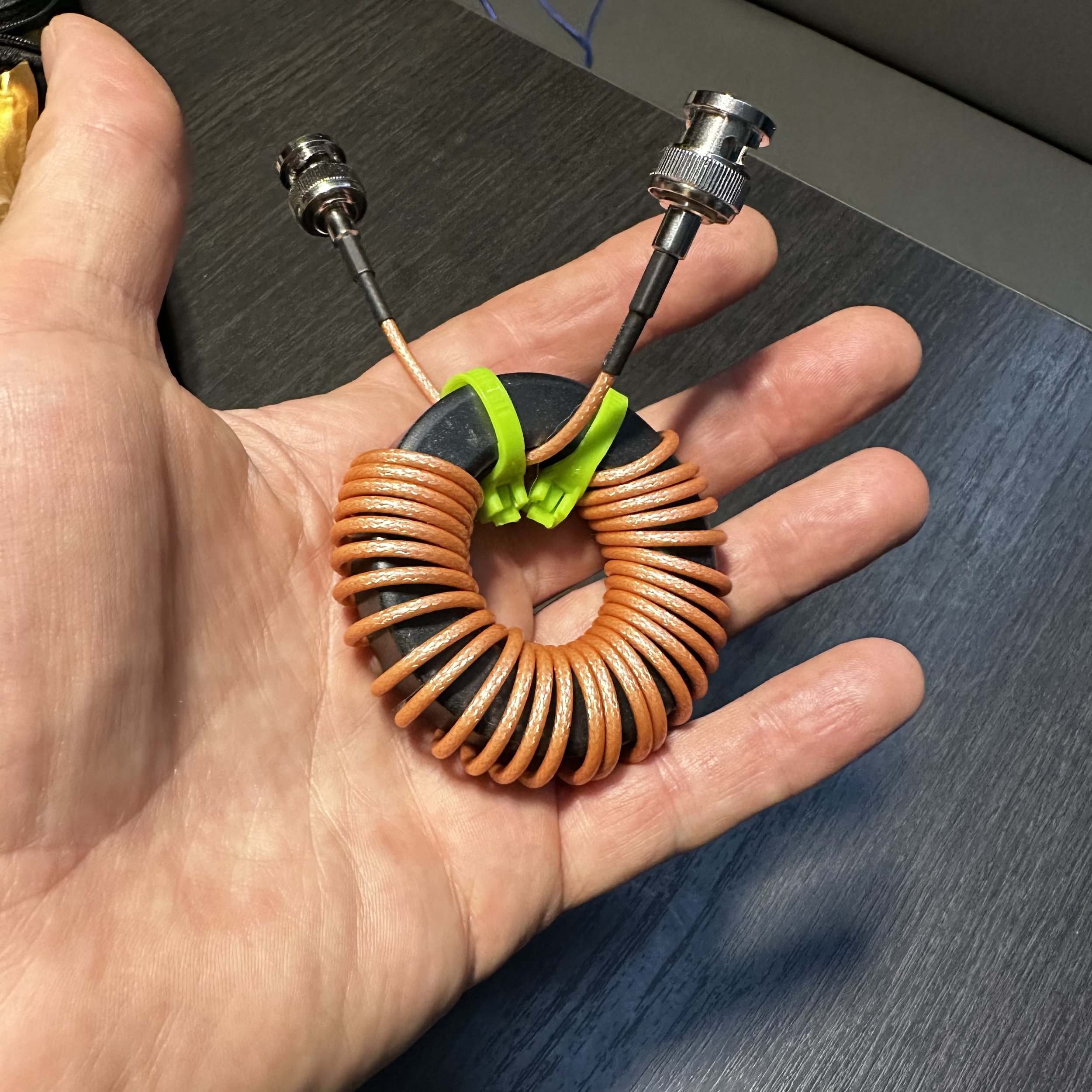
Note this test isn’t to determine which setup is the better setup, (well maybe it is if I am being completely honest) but rather to see if there was enough of a difference to warrant getting the specific composition toroid. If you will notice, the ferrite choke is much larger, this is because I learned from my mistake with the powdered iron version I used in the beginning. I struggled to get 14 turns of RG174 through the powdered iron core so when I ordered the ferrite core, I made sure it was big enough. Lol. My QRP setup for POTA is not ultralight weight, super minimalist portable but rather a “drive the pickup truck to the park and setup near the truck” kind of portable. I also learned when the ferrite core arrived that it would hold quite a few more turns of coax. Well… following my “more is better” philosophy I figured out what length would basically fill the toroid and that turned out to be 6 feet of coax. Hence the ferrite core has 30 turns of RG 316 coax on it.


The next thing I needed was a way to actually test the common mode current suppression. You see common mode current flows on the outside of the coax shield only.
This in turn required me to make up a cable that would allow me to connect the coax shield of the choke to both the port 0 and the port 1 inputs on their center pins while coupling the input shields together from those ports.
Enter Youtube at this point on how to use the VNA to perform this test. Of course, the test isnt 100% accurate as I couldnt perform the calibration correctly with the built up cable installed, but it does give me a close approximation to the performance I can expect.
As you can see from the picture above I simple cut a short jumper in half, soldered the shields back together and then soldered the center conductors to the shields attachments of two BNC connectors so I can pass the test signal over the shield only of the cable under test. This works surprisingly well but it is fragile so at some point I plan to put this in a simple project box.

The first one to test was the powdered iron core, which is the one currently in use in my POTA kit. I had bought this core with not much though being put into it. An RF choke is an RF choke is an RF choke was the thought process here. So I added it to my coax and happily used it for a while but occasionally got unwanted dits and dahs on my code if the coax was near the key cable. I noticed I could simply reposition the coax and it would stop causing interference. This made me question the choke’s effectiveness and here we are now. The VNA is set to 10dB per division and the whole amateur band with 1.8 mhz on the left and 30 mhz on the right. To save you from squinting I made a chart at or close to the bands I use to see the relative suppression and it is below for this choke.

As you can see from the chart, it works really well on 17, 15 & 12 meters but not really well past those. I dont know why it produces a 54dB null on 15 meters but that is kinda awesome. The performance on 1.8 mhz though is abysmal and I am guessing this is why I was getting RF induced into the keying line on 40 meters with only 13dB of suppression. So then I put the new ferrite choke into circuit and the waveform and chart are below.


Holy moly what a difference! The first thing I noticed was how broadbanded it was and the next thing was how low the waveform was! The poorest performers were the high and low portions of 10 meters and they still almost made 30dB!!! Wow! That 80 meter null is phenomenal and has me wanting to try a hamstick on that band. So this simply proves conclusively that I am an idiot and should have listened to start with…
Following my idea of “more is better” I decided to couple both chokes in series to see if the deep null on 15 meters from the powdered iron core and the 80 meter null from the ferrite would simply “add” together for some sort of magical double dip monster choke.


Well…It didn’t go quite to plan. There are two distinct dips… Instead of adding the two plots, it seems to more have averaged them together. This result is kinda disappointing to be honest. I was hoping to get over 50dB on two bands, but so is life. I am sure there is solid math somewhere that explains this in detail, but I honestly don’t know it, this is why I like to experiment and tinker with things. I can still learn something even if I dont have all the background (like the math knowledge) for a given idea. Also a quick note, my note at the bottom is wrong as it improved 17 meters as well. But it was late and I was getting tired. Lol.
In conclusion, if you plan to make a common mode choke for your HF coax, use the 43 mix ferrite for good performance across the band. Also, I didn’t try varying the number of wraps either. This will change the performance characteristics of the choke as well, so at some point I will probably do that but for now, I will just get on the air with my new choke and be happy.
I hope this helps someone on their common mode choke journey and keeps them from having to learn the same things I did the hard way so until next time, get on the air!!!
The Penntek TR-35 activates POTA K-2169 gloriously!

Click on the image to goto the WA3RNC website to get your very own TR-35 in either kit or factory built versions.
Today started off like most others with some time at work in the morning and then I had a few hours around lunch to do an activation. In addition to the usual activities, I have been using a variety of radios lately to see what I like about each one. Since I had activated most recently with the IC705 (by far my most favorite POTA machine) and so I wanted to use a different radio. I have been using the TR-35 lately in the shack, but wanted more field time with it to see how easy it would be to work with.

33’ wire radiator and two 10’ counterpoises bundles for storage. I love these velcro tie back straps.
So on this outing, I used a 33’ wire “vertical” antenna that I pulled into the tree with my throwline. Once the vertical was up, I laid out both of my counter poise wires (I think they are 10’ each) and for good measure I spaced them into a v pattern for kicks… On my next trip out I plan to see if putting them at 90 degrees to the radiator and 180 degrees from each other helps, it probably does and I have been paying the price all along with my silly V setup I have been using… lol…anyway…

This is a great antenna tuner and still happens to be in production! The new version is a little more streamlined but it is the same internally as this older one.

Back of the antenna tuner is just as busy as the front!
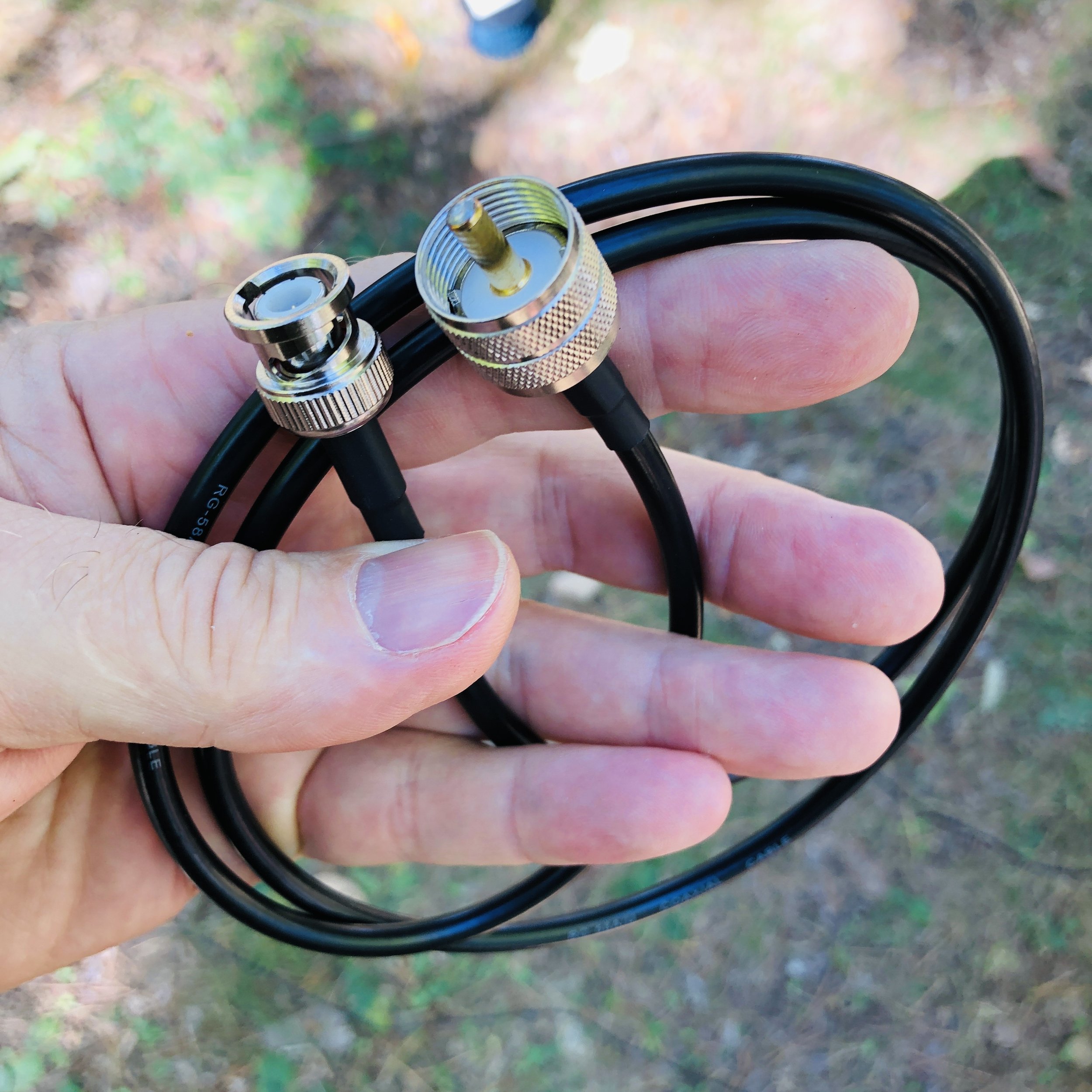
Once the antenna was up, I connected it to my MFJ travel tuner to the random wire lugs on the back of the unit. Then I use a special coaxial cable I bought from Amazon that has a BNC on one end and a PL259 on the other. The antenna tuner uses SO 239 mounts on it so the PL259 couples that end and the other end is natively a BNC on the TR-35, but I have also adapted my nanoVNA to BNC as well for simple tuning. Since my Ten Tec Argonaut 5 is SO 239, I have bought an adapter to convert it to this same system so I can tune the antenna easily on it as well.
This is not my idea, my late friend K4GC Brian was the person that taught me and Roger how to do this. It makes perfect sense when you think about it though so I started doing it once I got the VNA. Otherwise it is this trick of tuning till you hear the noise level peak and that is the best you get. This way works but it is possibly not centered where you need to be. Since the TR-35 doesn’t have an SWR meter, it has lots of protection circuits built in to prevent you from damaging the transmitter from tuning or operating at full power with poorly matched antennas. It has a current protection circuit as well as a thermal protection circuit, if either one activates, you really should check the antenna and see what is wrong, then reset the radio and try again. Alternatively, you could bring an SWR meter with you to get the tuner set as well if you don’t have a nanoVNA…
Amazon is a great place to find these sorts of oddball parts, several of the items in this blog today came from them.
Since everything is now BNC connected, I can quickly pull the cable from the radio, then connect it to the nanoVNA and see the tune on the tuner visually! I run a trace with the smith chart and a trace with a SWR line graph as well, with both of these running at once, it is pretty simple to get the SWR and the impedance really close to what the transmitter likes. Once I get the tuner adjusted to the band I want to use, I simply move the coax back over to the radio and off I go…

BNC is where it’s at with this system…

Here I am tuning for the 17m band, note that the VNA is showing the SWR of 1.541:1 and the impedance is 54.8 ohms and slightly inductive at 18.096mhz. I could dial some more of this out with the tuner, but it becomes a law of diminishing returns at some point with the tuning and this worked just fine. Note also that the SWR is fairly flat in the range I planned to work in also. (the yellow line represents SWR vs. Frequency)
Some things to note about the TR-35 that I noticed. The first one is that the headphone jack is wired from the factory for a mono plug, not the stereo plug that every set of headphone made in the last 30 years uses…why? So you go to Amazon once again and buy this little adapter to convert your normal headphones to a mono plug… You can go into the radio and change this on the circuit board, and the instructions even detail this mod, but you have to risk damage to the radio and it is a lengthy tear down and assembly process to get the board out of the case. Lot’s of chances to break something important if you asked me…so the adapter it is… Another thing I cant seem to master is the keyer programming. It is a simple operation to input the message into the keyer, but upon playback, it has odd spacing and sounds disjointed for some reason, I have tried slowing down the keyer speed to no avail, I will figure it out at some point, but for now, I don’t have that one working right. To put it plainly, it just sounds wrong on playback, like I was saying, it could be my sending is causing it, but I have not figured it out as of this writing. I have seen videos of it working as advertised so I am confident I can get it to work…eventually.

Amazon…they have literally everything at this point.
I powered it with my battery I use for my 705 activations, actually lots of the accessories I used came out of the 705 kit today for this activation. But I found this battery is way overkill for the TR-35, so I plan to get a smaller one for the travel battery to build the kit with. Probably something in the 4 or 5Ah range instead will be fine. I am also going to eliminate the voltmeter inline for the travel rig too, just a cable with power-poles on one end, the 2.1mm plug on the other and a fuse in line with the power. It pulls 5 watts wide open, does it really need 14 gauge wire??? Lol. I actually used the power cord for my IC-705 to power this radio today, the connector worked just fine. But I will make a cord just for this rig to go in the kit.

I am also still using the N6ARA tiny 3D printed paddle that I bought a while back(also from the 705 kit today) this is a device that although I like it, it has some problems that I have found. For one, it is really small and I didn’t take that into account when I bought it. It is available in a couple bigger sizes and I should have gotten one of those. This one is in my mind, one that should be a backup or a SOTA paddle or something like that as it’s main advantages are that it is light and small. What I have found from using it regularly is that is gets dirty contacts and you have to mess with it some and clean the contacts before it will send right once it gets some age on it. This is because it is plain copper/brass contacts (pc board with a brass arm on the “levers”) and they tarnish in a matter of days to the point it wont send properly till I clean them. I am looking into three solutions here, a nice travel key like the Begali travel paddle, make my own travel key, or buy a used small foot print paddle off the boards. I am actually leaning towards the Begali for now to give me time to design a key I can share with the world as well as for my personal use. Anyway, who doesn’t like a nice Begali key?

My N6ARA tiny paddle… I love this little key.
I have an alternative reason for working with this radio so much as well. I am going to be doing some traveling in the coming weeks and months and I want to take a radio that is not too large so it is easy to pack and carry around and such. This means smaller is better and the TR-35 is my physically smallest radio. This means it gets the nod based on size and now it also gets points for performance. Even if I cant figure out how to program the memory right. 😂
The kit will fit into one of several of my camera bags that I currently have so I don’t have to purchase a new bag to carry it in. I have found that camera bags work really well for QRP radios too, they just fit really well into old camera bags for some reason. By the way, I didn’t think of this idea either. I got this idea from my cohort KV9L who did this for his FT8 rig and I straight stole the idea from him. LOL.
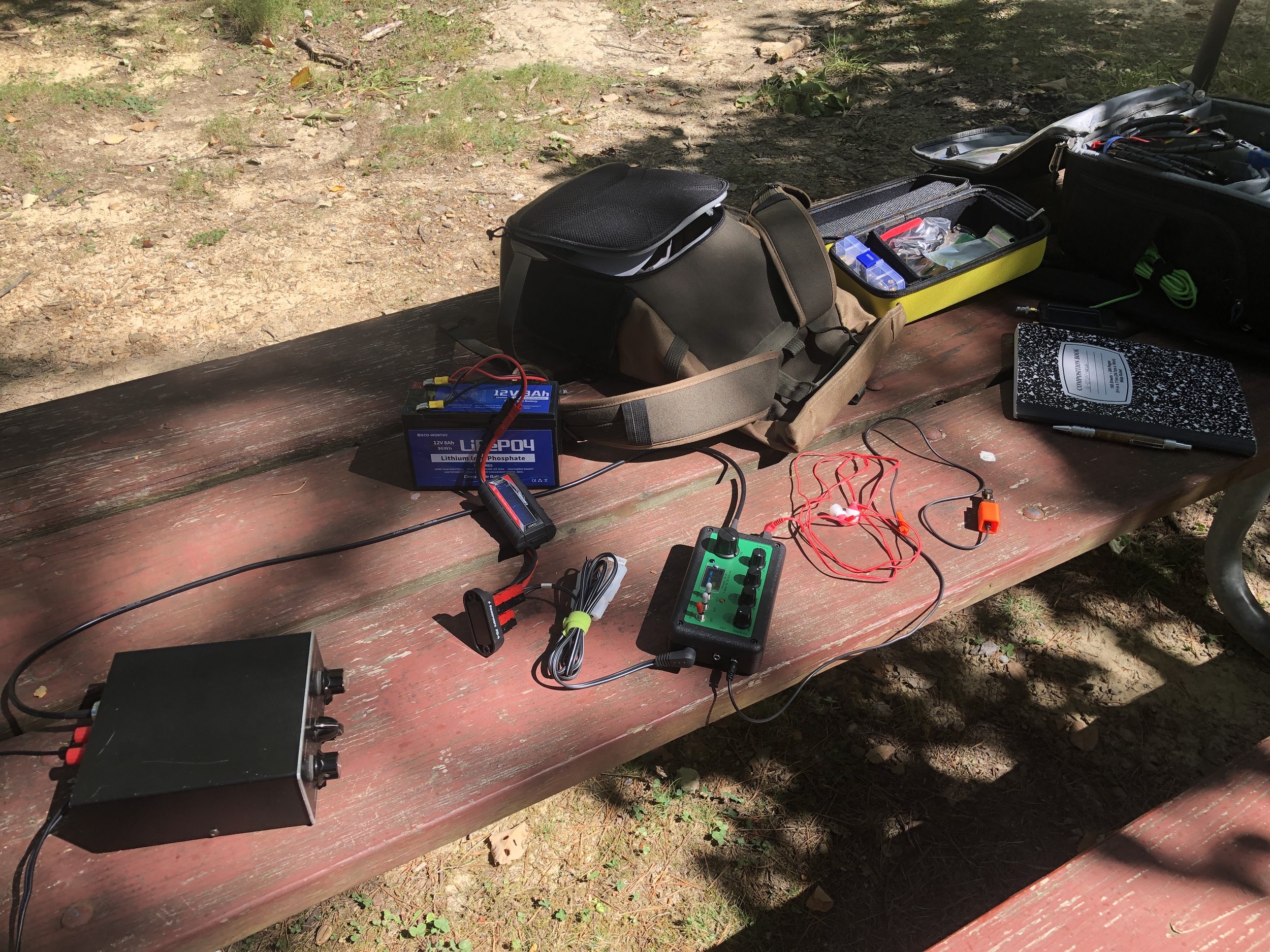
Parts everywhere today! I took the IC-705 bag to “rob” all the support gear from so it would be a simple deployment and I have not built out the TR-35 go bag kit as of yet either…

I really like the aesthetic of the TR-35 as it has everything you need and nothing you dont. It really is an incredible little radio. I didnt build mine from a kit, I bought mine factory built and aligned so I could get on the air sooner.

1 hour on the air netted two pages of QSOs! That is awesome for me!
Logbook looks good with a good spread of contacts today with several from Canada in the log for a change. I usually only get one or maybe two Canadians and today I think there are at least four! This was with only about an hour on the air too. That is really good for me since I run QRP power. The map below shows how far 5 watts into a wire vertical will reach with a little understanding of how to use it. All in all I really like the TR-35 from Penntek, it a great little QRP radio that fits into what I enjoy doing in amateur radio, low power CW operating…

So if you have not done it yet, please like this blog post and if you have a RSS feed, you can sign up there too. I really appreciate your reading along today and if you have not done it yet, get your gear out!!!
Thanks and 73
David - WK4DS
Simplifying antenna tuning with a manual tuner and a nano VNA on location.
Please note: This is not an instructional presentation on how to use the nanoVNA to tune your antenna, but rather a simple primer on how I deploy mine in the field and why. There are tons of videos on YouTube that will show you how to deploy the VNA in a tuning operation and at some point I will probably do that here, but I wanted to share the idea of USING the VNA to tune the antenna WITH the antenna tuner prior to hitting the transmit key and protecting your radio transmitter finals. With that out of the way, let’s dig in!
Something I have always hated doing is the whole tuning operation and transmitting while I did it. Just screams of poor operating practices to me for some reason. I know it is needed though, so I do it… Till now. You see, some radios don’t have an internal antenna tuner built into them, like my TenTec Argonaut 5. This radio is a joy to use but you either need resonant antennas or a tuner to match the radio to the radiator.
Enter the nano VNA (Vector Network Analyzer)… I found out about these little devices from my friends Aaron and Roger and finally got one for myself. Back in the day, about 15 years ago, these little pocketable widgets would set you back about 20,000$ and were the size of a suitcase! Now, technology has caught up and these things are very affordable (about 50$ US) and are even battery powered so you can take them to the field easily.
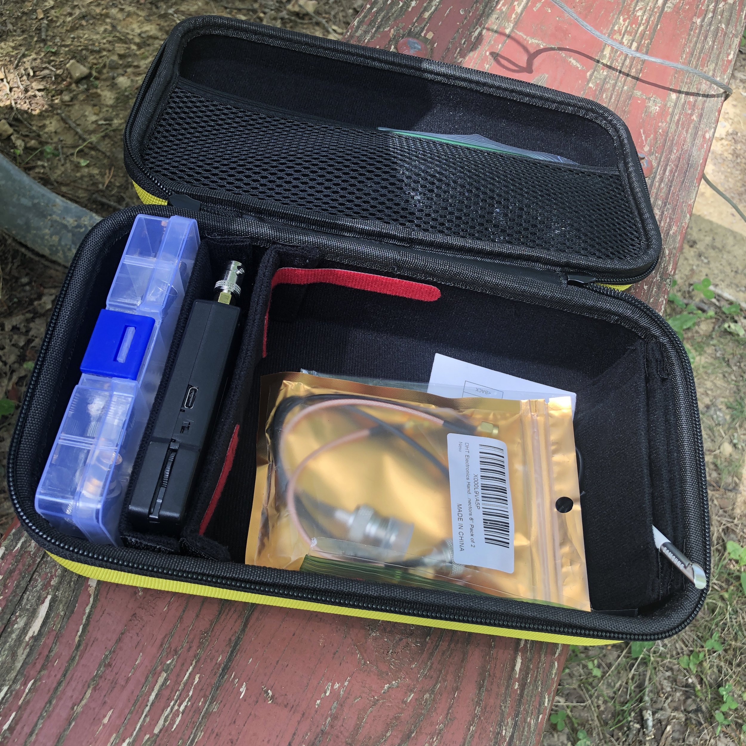
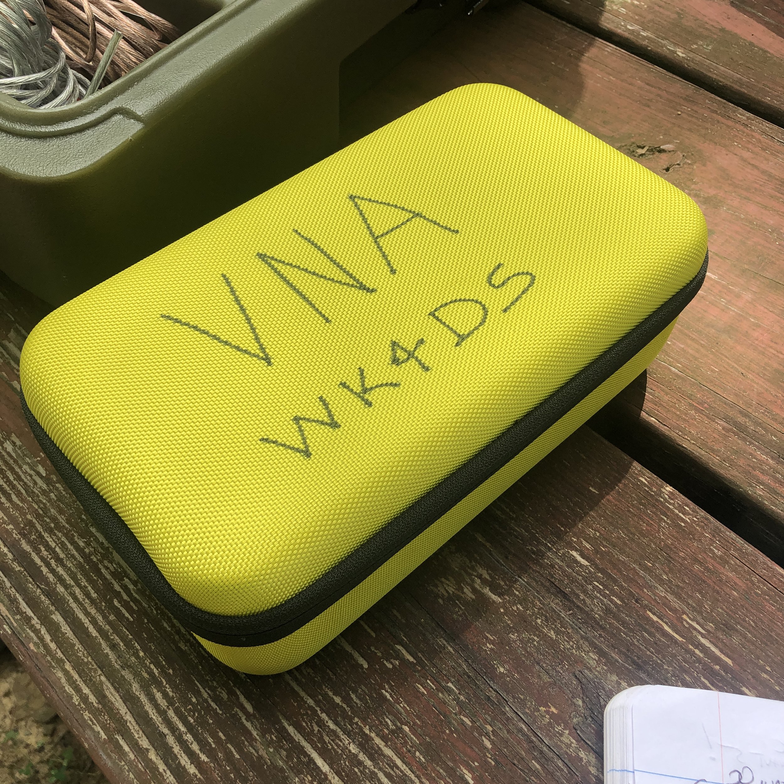
I built this kit for mine with a divider box of adapters (far left in picture), then the nanoVNA is the black device next to that, then the large bin is for cables and such and lastly I have a stylus as it is easier for me to use that than to use the guitar pick looking device that comes with it. This one is recovered from a old Samsung Galaxy Note. I got the case at the Huntsville Hamfest from GigaParts if you want one of them, they probably have them on their website, but I am not sure…
This thing can do all sorts of measurements, but the most often used by me is antenna tuning. If you want to know more about what it can be used for, just search YouTube for nanoVNA and you will get an idea.

In this photo you can see a lot of data being presented on the nanoVNA, such as the frequency range I am testing, two different measurements, one on a smith chart and one on a linear line chart of SWR versus frequency. What the smith chart shows me is a graphical representation of whether the load (antenna) is capacitive or inductive, and what the impendence is at the selected frequency as well. The line graph shows SWR plotted versus frequency and this allows me to maximize the tune for a particular frequency visually, all without risking damage to my radio amplifier section from mismatched impedances or high SWR. The nanoVNA does have a signal generator in it so it is technically transmitting, but it is VERY low energy.

Manual tuners in the past, such as this vintage MFJ 941 worked really well, but are slow and you only get information for the exact frequency you are tuning at (which usually is not the frequency that you are going to use as you dont want to tune up on top of the person calling CQ). This meant long periods of on air transmitting a carrier tone while adjusting the controls on the tuner to add capacitance or inductance to the the antenna to match as best you can so as not to damage the radio.

Radios like this old Ten Tec Argonaut 5 do not have automatic internal antenna tuners in them and even a lot of newer radios don’t have these tuners in them to be honest. These radios either need a tuned antenna that has been built for specific frequencies or a tuner to match the non-resonant antenna to the radio. The nanoVNA allows the operator to tune easily and this happens much faster than on air tuning. Tuning this way also protects the radio in the process. What I really like is that I can see if the bandwidth of good matching SWR to the radio so I know immediately that I can tune the VFO around and not have to retune the antenna while I am on one certain band. Some antennas and some bands don’t play well together and you can see this too… graphically. This allows you to know that on those particular bands, you will need to tune when you leave the safe zone of swr. It is so much more powerful to tune your antenna with this little device.

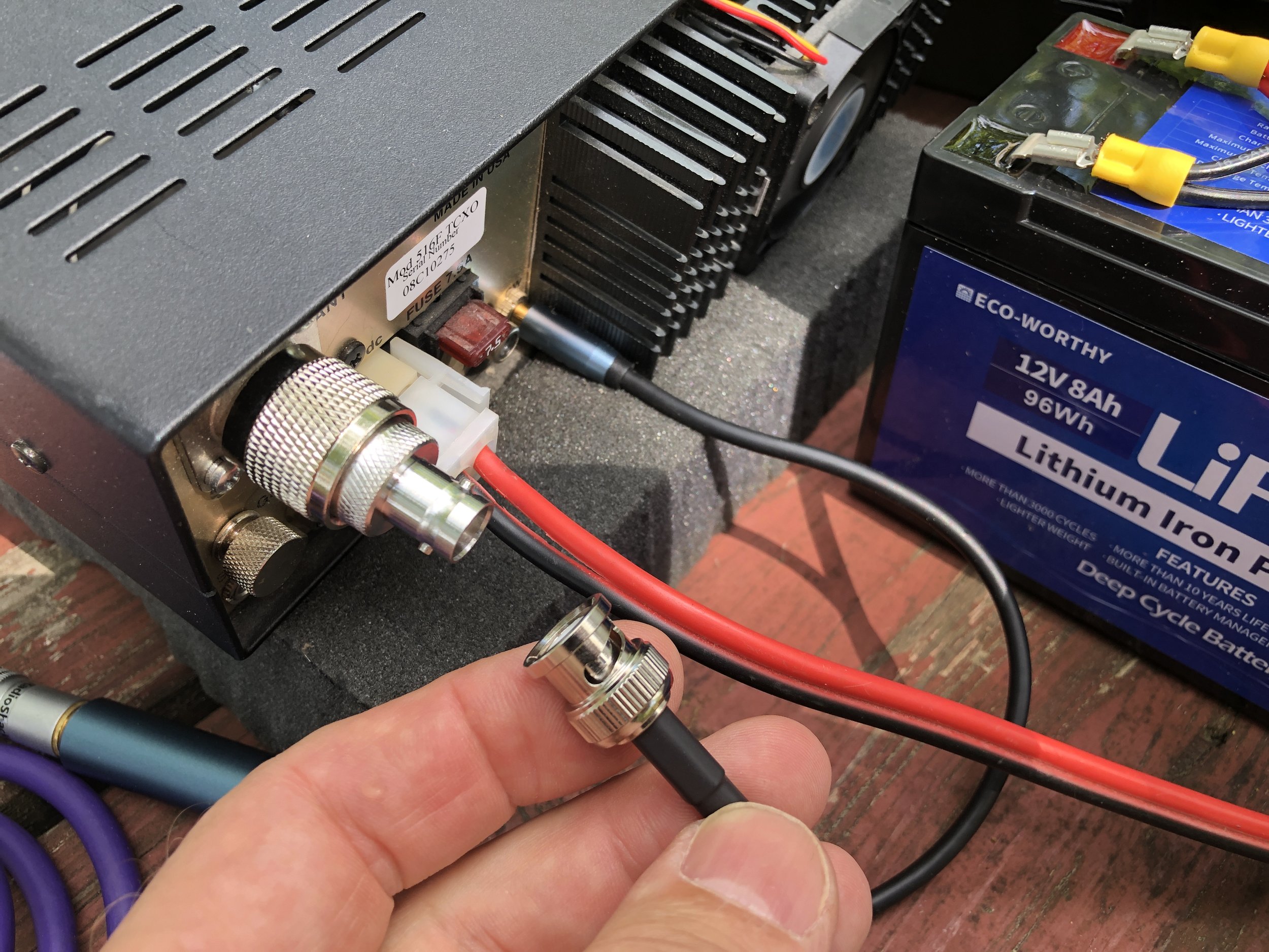
This is the setup I use to be able to easily connect the nanoVNA to the antenna while out on location. The radio comes equipped with SO239 connectors so the antenna has to be screwed on to the radio with a coax cable normally. The modification I made, to make this process super fast, is to add a PL 259 to male BNC adapter. Then I add a SMA to BNC to the nanoVNA and now I can simply and quickly remove the coax from the radio and connect it to the VNA for analysis.
I also made a simple note page to get me close when i go from one band to the other. This way the time to get back to a tight tune is even faster. I also made some notes about how many radials and such. I keep these notes in the case with the radio and tuner.

This has been my biggest blog to date and I really liked writing this one for you. If you have any questions, just drop them in the comments below and we will try to get you an answer as soon as possible. If you think tuning your antenna like this is a good idea, you can find these on Amazon with a simple search. Also, they really are inexpensive. You can also get all of the adapters or accessories on amazon as well. It is all there, all the training you will need can easily be found on YouTube as well, plus some… Now go get on the air!
72
David
WK4DS