WK4DS Amateur Radio Blog
Search Posts
UPDATE - sBitx V3 with Firmware version 5.4

So the dev team working on the sBitx software suite (unpaid I might add so I suggest you drop in on them and give them a donation for all this time and enegry they have put into this for the community) has dropped ther latest version of the sBitx SDR firmware and it is version 5.4 and let me tell you, this is incredible!
Highlights of the new firmware for the sBitx Software Defined Radio
This is taken directly from the drexjj GitHub repo page so I dont get something wrong. Goto this link to see more about this project and to help support the team.
Here is the list for JUST THIS RELEASE!
v5.4
New Features:
sBitx IQ improvements
enhanced VFO, complex mixing and down-converting
improved processing of I and Q data in the sBitx receiving pipeline
AGC function and AM detector changes to work in updated pipeline
FM Mode and Squelch
Added FM mode and squelch control for use on 10M and transnverters
Text console can scroll back to view and work with up to 500 lines of history, in all modes
Added support for Touch Display 2 and larger displays
Makes it easier to touch and see the buttons on a Touch Display 2 or external display
New file is read upon sbitx startup called display_settings.ini where you can set the display type or resolution
display_type=1 is for the original, older 7 inch touch display
display_type=2 is for the newer 7 inch touch display
ui_scale can be changed for use with a larger display
Added styles option to customize the sBitx application.
Text size, font, color, and types are now supported.
Styles templates are stored in the data folder as tpl files.
If there is a file named user_style.tpl in the sbitx data folder, then it will load it on sbitx startup.
If the user_style.tpl file is not found then it will load default_style.tpl if it is present.
If none of these files are located, then it will load the factory style we are all used to.
There are sample styles in the data folder that can be loaded. Just have to rename one of them to user_style.tpl
Added mode_bal to hw_settings.ini to balance LSB and CWR to USB and CW.
0.8 is a reasonable value.
Also harmonized filter band edges.
removed old ssb_val
Controlled Envelope Single Sideband (CESSB)
enable via the button in menu 1 or the 'cessb on' command
Added Tune function to FTx modes
Added NBFM mode with CTCSS and Squelch
Added squelch control to AM mode
Added option to use USB audio devices for sound routing (speaker/phones and mic input)
The options are in the Set dialog box in Menu 1
Added Out-Of-Band and license class indicators
Shows color strips or shading for bands edges and US license class
Each file can be customized outside the USA
More details and instructions in the oob_limits files in the data folder
Added ALC power limits by band, if RF power exceeds limit it is folded back to limit
Default is off until a limit is set in hw_settings.ini by adding line max_watts=nn to band data after f_stop
When activated message is given in spectrum between Power and VSWR
Power reduction is released when RF power drops below bamd limit
Added swrsweep
usage: select a band then either
enter cmd swrsweep n, n where n is the number of sample frequencies or
in menu 1 set SWRSTEP to the number of samples and click on SWRSWP
uses TNPWR to sample vswr at the n sample points evenly spaced between band limits
displays results in console
esc key cancels sweep
Added time out feature to SWR alert
SWR alert ends after 10 seconds without needing to first transmit with SWR less than max_vswr
Added HPSDR 'Protocol 1' support to provide sbitx I and Q data to external SDR apps over WiFi or ethernet
Starts when sbitx starts, console will show "hpsdr: streaming STARTED" when SDR app discovers and connects
Good support for SDR app receiver functions
XMIT not yet supported, will require CAT/Hamlib connection
Changes:
GUI
Moved Direct Frequency Keypad to a new button called PAD and added quick buttons
Swapped button placement on main display
Moved eptt & vfolock to menu 2
Menu 1 is reserved for mostly audio related controls
CW Decoder
Fixed colors of sent and received text on console, use new lines when doing T/R switch
Only displays cw stats (WPM, dot/dash ratio) when they are meaningful
Less garbage ouput when only noise is present
Replace sliding window in denoise function with EMA filter
Improved accuracy with better weak signal performance
Replaced viterbi with simpler classifier
Simplified code of own TX decode process
Set BW to 50 when using decoder is recommended
Web interface
Added more controls
Gridmap new options: Square or round Grid dots; Seen Grids; Unlogged Grids;
Power and VSWR readings updated more often, from every second to every 1/2 second
Updates are now as fast as bridge reads allow
Minimum power for VSWR calculation increased to help eliminate invalid reads at very low powers
Fixes:
APF init Bug
Fixed a bug where APF would not initialize properly
Audio Cleanup
Made a small change to cleanup the static between TX to RX
APM sampling improved for better regularity
VSWR initialization when user disabled fixed
max_vswr=0 now restored as no max vswr protection at startup
Fixed scope intensity where it now loads and restores previous setting
Fixed Macro loading and F1-F8 buttons when changing modes
Web Gridmap red Grid dots now shown when QSO is logged
Fixed expansion of SENTRSTCUT in macros
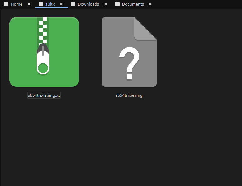
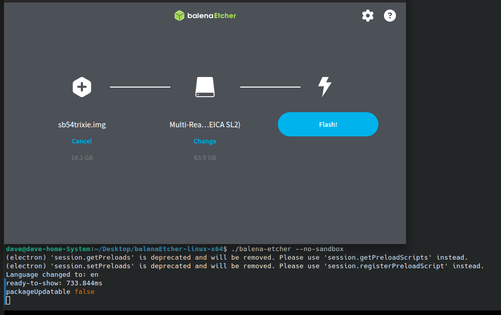
Downloading and burning an image to your microSD card
Firs thing you need to do is go download the new image. The new image is a zip file so you have to extract it and then you can move on to step 2… This is where you use a tool like Balena Etcher to write the disk image to a micro SD card. I use 32GB cards since it is what the radio started out with. They seem to work just fine to be honest. I did have to write the image twice for some reason. The first time the image would not boot past the splash screen so I reburned it and then it worked fine. Balena Etcher is an easy to learn tool that makes this process pretty simple to be honest. If your using Linux it might take a little to get it running, but google will tell you what to do here as well. I ended up running it in my terminal so I could shutoff the sand box feature. I know this is probably a bad idea to remove the sandbox but I have confidence in Etcher so I am good with it. Launching it from the terminal, you are presesneted with this panel. The first one is where you choose the disk image you want to burn, the second one chooses the media (hard drive, memory card or the like) and then you click flash and wait… It will take a few minutes and you are presented with a ready to use version of the sBitx software ver. 5.4. You still need to copy a couple of files from your existing version of the sBitx you are using. It is not a big deal to do this as you just need to copy them to a USB memory stick so you can later put the back when you swap micro SD cards in the radio.
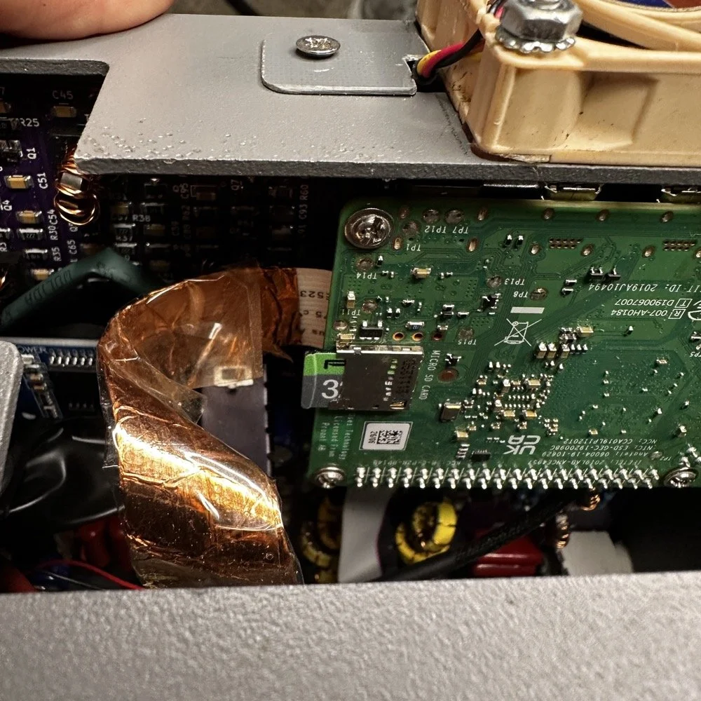
The next step for me, involved me taking my radio apart some what. I use the on board Raspberry Pi micro SD card slot on the Pi. This means I have to take the front of the radio loose from the chassis and open the radio enough to be able to swap out the two sd cards. Dont make my mistake and use the same card for both images. Make sure you use a new card for the new image and save the old one in case something goes wrong so you can go back to the working version while you solve the problem. This is pretty easy and only requires you to remove 4 screws to succeed. Once the new card is installed, you are off to the races! Just power up the radio as normal, being sure to have either a dummy load or a tuned antenna attached as it will auto launch the radio app and if it is on FT8 it just might start answering a CQ if your not ready! HaHa! The card really is easy to reach, just be careful to not unplug anything like the video cable you see right next to the card. I have my cable wrapped in copper tape and grounded to help reduce RF hash from the Pi, this is a hack that actually works really well. This cable is one of the prime culprits of rf hash in this radio so just doing this one mod will improve your experience a lot.
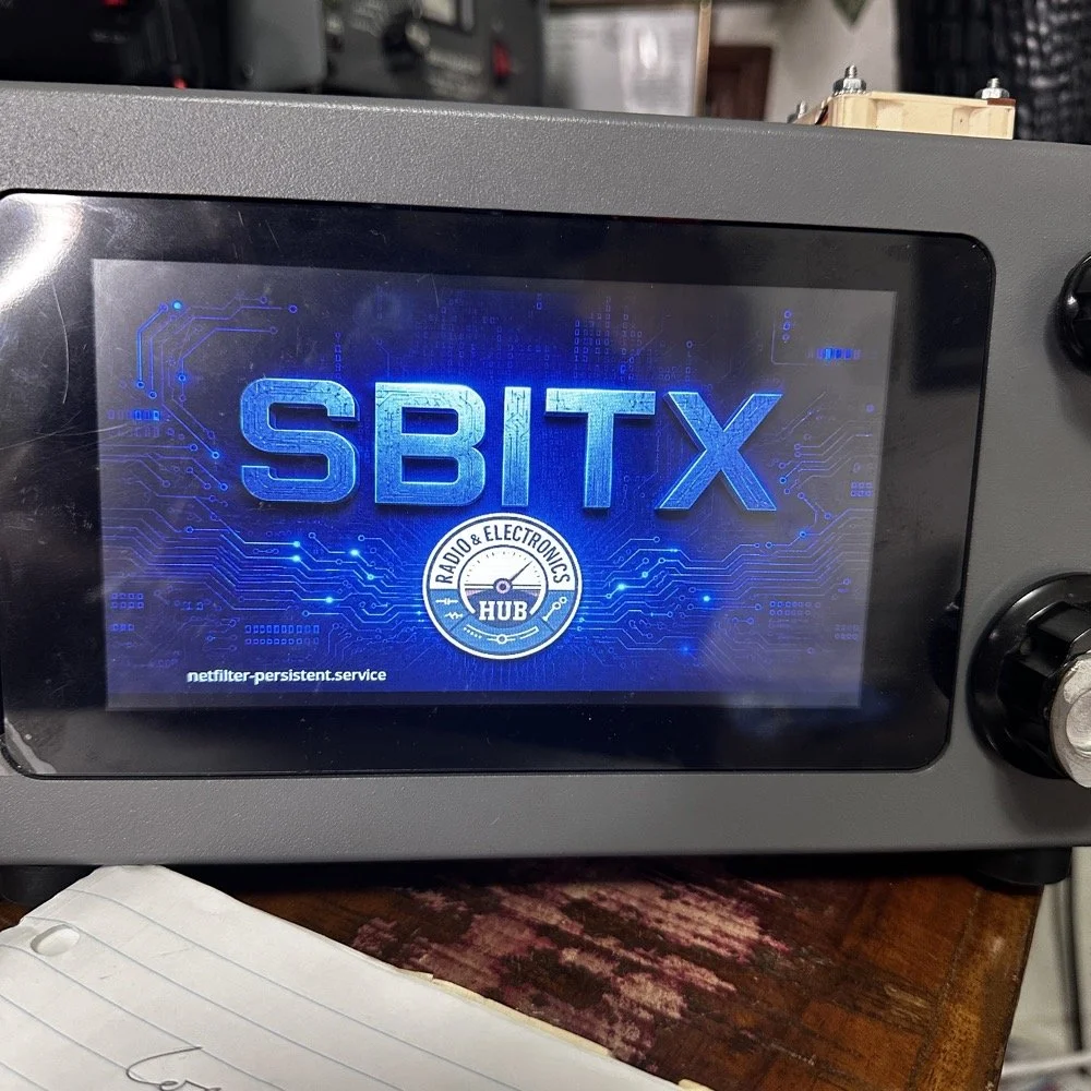
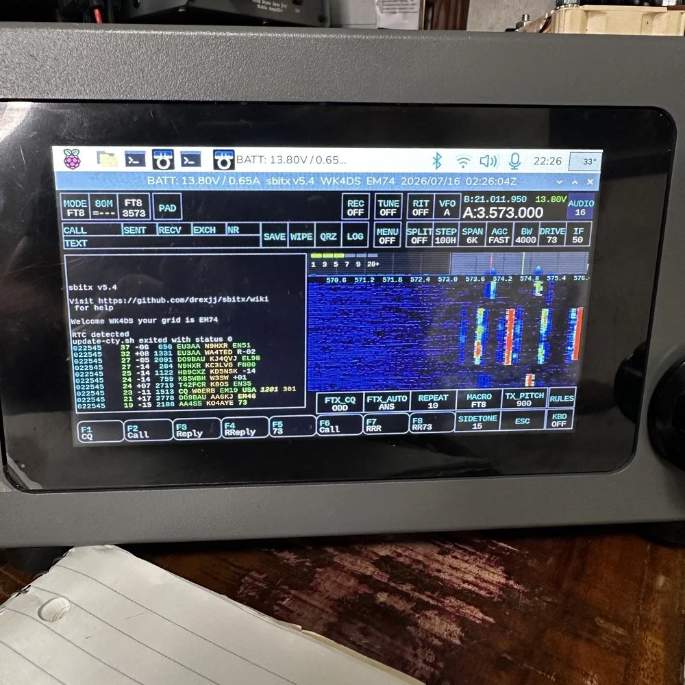
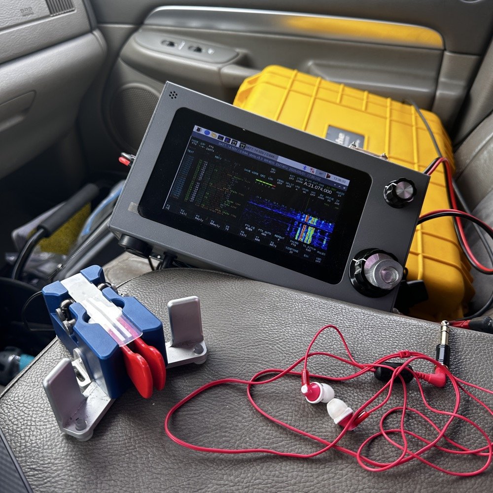
This is the new splash screen that you are greeted with while the software package loads everything. I really like this new look the dev team brought to this release. Once the software loads, it will auto lauch the sBitx radio app and you will have the view below. It is in FT8 mode here since I was last using this mode and band. There are some tihngs you need to do before you start using the radio, such as entering into Menu 1, then touching the “Set” button and in here you will enter your callsign and grid locator you are currently operating in. This is used for logging and digital modes. But it helps to do this first thing so you dont forget. I also keep a note about this in my case so I dont forget to do this step when I am out traveling and activating POTA parks with this radio.
Personal thoughts about the HF Signals sBitx SDR radio
I only use my sBitx for a couple of modes. FT8, FT4 and CW. I rarely use SSB or any other voice mode for that matter. I just prefer CW to be honest. That being said, I tested out the keying on the current release and it works perfectly for me. I normally dont run over about 22WPM though so if you work faster than me, just know I wont be speeding up with this radio…lol. I can get decent code out of it at 25WPM, but now we are getting into the realm of my skills not being up to the task too… sooooooo. I dont know which is to blame past this point.. HAHA!
I like FT8 as it will work when the bands seem to be closed for even CW. That is nice if you are activating a POTA park and the band closes on CW with 8 calls in your log. This way I can hop over on to FT8 and more ofter than not, I will get those needed calls in the log and probably more, in spite of the fact that the output power on a band like 15 meters will only be about 12 to 15 watts depending on battery level. I can get a lot more output power on the low bands but on the higher bands I will not get a lot of power out. This just further solidifies my stance on using FT8 in poor band conditions and the ability to make contacts with it natively in the radio. I would like to say something else about this radio. I really like the community around it. Sure there will be the occasional disagreemnt here and there. It is a group of humans after all… But for the most part, it is a group of experimenters and coders and general operators that love to tinker with their machines as much as operate them.
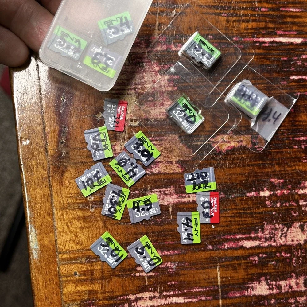
Speaking of images on disks. Over the last few years I have amassed a small collection of different images. You might think this is silly, but there is a method to this madness. You see, for one, I have a full collection of images starting with the factory shipped version that came with the radio. The factory version is the one with 381 written on it, as this is the serial number of my radio. I have a copy of the Field Day release and the first 64 bit release. As time passed and new versions were released, I get them and burn them to a new card and save the old one. I can install any one of these cards and it will instantly become that version radio again. That is pretty cool. Honestly though, the other reason I keep them all is that there is logbook data stored on them as well as the later versions all have my config files on them that I can get to should the card in the radio die for some odd reason.
Another really good idea for a person getting one of these radios is to use the disk copier app and make a backup of your image on a new micro SD card. This way should the one in the radio die, you can simply replace it and keep going…right after you make a new back up. The reason I keep circling back to this is that these card are not the most reliable on earth. All of mine have worked well, but there has been some people that have had their card get corrupted and dont have a backup. That is tough spot to be in to be honest. Anyway, I thought I would share a little about one of my favorite radios and what is going on with it.
73
WK4DS - David
Activating with the TenTec Scout 555 after a 2 month hiatus!
When you love CW, you tend to migrate to certain kinds of radios. I migrated to TenTec and Elecraft rigs mostly, with a few smaller radios thrown in for good measure. I love TenTec radios for CW operation as they seem to have been tailor made for the mode. They work well as SSB machines too, but they REALLY shine on CW. Since we all know this about me, it is a given that if I want to activate with a simple radio that isn’t a lot of fuss, that I will choose the Scout 555 or mt Argonaut 5 over about anything else in the shack.
When you love CW, you tend to migrate to certain kinds of radios. I migrated to TenTec and Elecraft rigs mostly, with a few smaller radios thrown in for good measure. I love TenTec radios for CW operation as they seem to have been tailor made for the mode. They work well as SSB machines too, but they REALLY shine on CW. Since we all know this about me, it is a given that if I want to activate with a simple radio that isn’t a lot of fuss, that I will choose the Scout 555 or mt Argonaut 5 over about anything else in the shack.
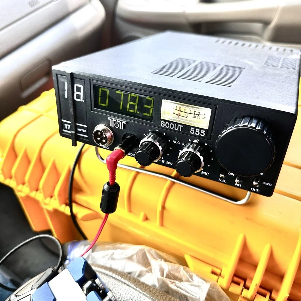
TenTec Scout 555 ham radio running cw on 20 meters
Setting up a POTA station at a local state park
When people start out activating a park in POTA, they tend to want to go to a local park first to get the bugs out of their kit. I am no different here. The only real exception is that I love going back to this park over and over. Back to the subject at hand though, I normally setup in a similar manner every time I go to a park. It usually goes something like this.
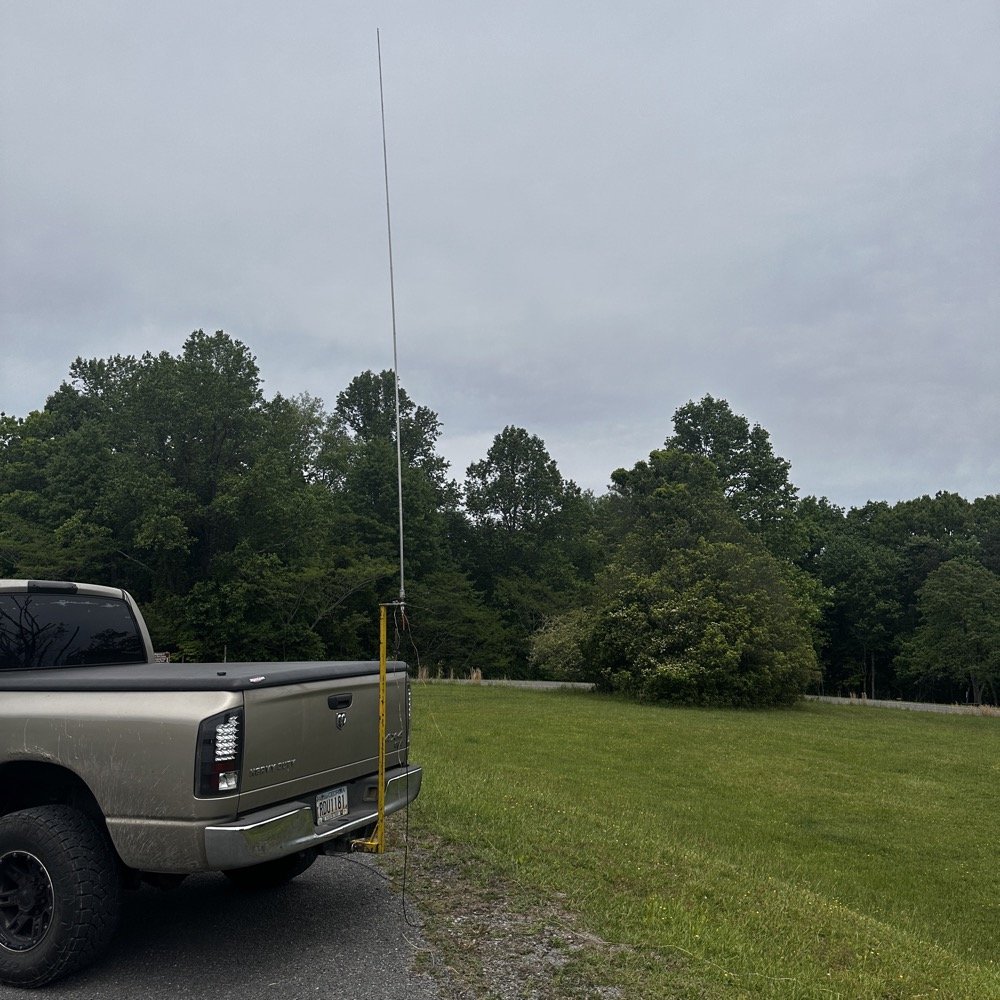
Find a spot that I can back into the parking space since my antenna mount is built for my receiver hitch on my truck and I prefer to lay ground radials so I don’t want people running over them when they drive by.
Once backed into the space, I will deploy the antenna first. I do this for a couple of reasons. First is that I want to get it up as fast as possible to avoid rain if it is imminent. Second I will spend some time tinkering with the antenna system to see what it does on the nanoVNA and this is kind of fun to me by itself. Antenna theory is fascinating and I love looking at how these devices work. Once I have the vertical up, radials deployed and the coax ran to the truck cab, I move on to the next step.
Tune the antenna to the band I am going to use. This seems obvious, but I have forgotten to do it in the past and it doesn’t work well unless I do it… I use the nanoVNA and I will usually tune the vertical first by collapsing it till I am close to the desired frequency, then I will move the radials around till I have the best SWR possible with the system I have deployed. Usually this lands me between 1.1 and 1.5:1 SWR at the base of the antenna.
Get out the radio and deploy it in the front passenger seat of the truck like you see in the photo above. I use the storage case for the radio as a table to sit it on. This works really well. I keep the keyer and cables for everything in the case with the radio. This even includes the earbuds I use with it. The only thing not in the case with the radio is the Begali Traveler key as it lives in a case of its own.
Setup the computer to log with (if I brought it) or get out the pens and notebook. Go ahead and write all the pertinent data in the log or computer before I start calling CQ.
Spot my activation on the POTA website before calling CQ as well. This has turned into a mess for me in the past to be honest so I do this step before calling QRL too. I want the whole system to be primed prior to starting the activation proper.
Call QRL and find a clear frequency before launching into calling CQ. This is a big deal to me and a step I make a deliberate effort to do so I don’t walk on someones QSO that I cant hear immediately.
Once all of this is done, which takes only a few minutes in reality, I start calling CQ and get going. Now I also understand that my spot and my actual operating frequency might differ due to people being on a frequency that I chose to start with, but this isnt too big of a problem as the RBN will usually update it pretty quickly once I start calling CQ.
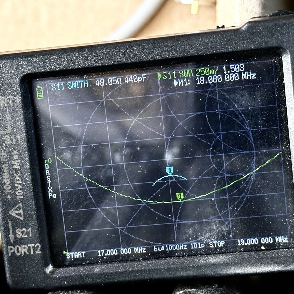
Tuning the antenna for use on a band.
As you can see in the above photo, I have already tuned the antenna for use on the 17 meter band. It is centered on the CW portion of the band and I have also tuned the radials to get the lowest SWR possible with the setup like it is. With it like this, I think I am going to use this plot to figure the inductance and capacitance on the Smith chart to see what it would take to get it to 50 ohms resistive or as close as possible to that. This is why I use the nanoVNA too. You can see the plot of SWR versus time here on a portion of the radio spectrum of my choosing. This time I chose 17mHz to 19mHz and the marker is set to 18.080mHz for my point of reference. With it set like it is, I can also see it is at 48.05 ohms of impedance and it is capacitive 440pF as well. I can take this data directly into the Smith chart and calculate the needed components easily.
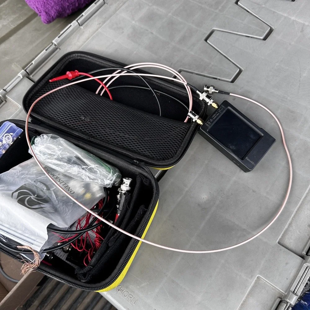
This is the setup I use currently. I find it easier to use this small jumper than trying to read the nanoVNA directly connected to the base of the antenna. The sun makes it very hard to read this device and adding the short jumper allows me to put it in the shade. Also, just look at how small this instrument is compared to regular antenna analyzers… That one thing in itself makes it a winner in my book.
The procedure for tuning goes a little like this. I will first get the antenna put together. This whip is long enough that it will tune to about 12 mHz if fully extended. This is good as it will allow me to shorten it to 20 meters by simply collapsing a few sections. Then when it gets close, I will pull down the bottom section a little at a time till the curve looks like what you see above on t he nanoVNA. I try to get my rough tune by shortening the top first as those sections are smaller in diameter and doing this will allow for the passband to be the widest possible. I can usually get the whole CW portion of the band this way on everything except 80 meters which has a huge area for CW… also this vertical is woefully short for that band anyway…but that is a different conversation.
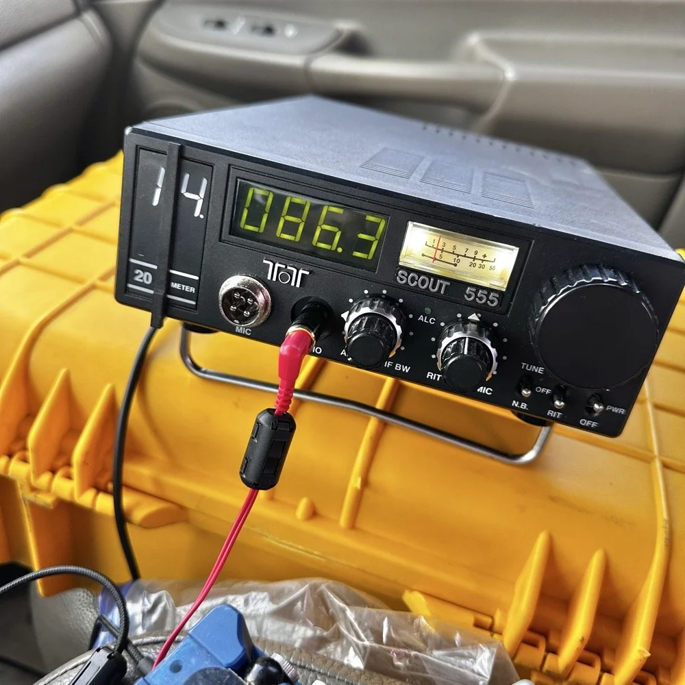
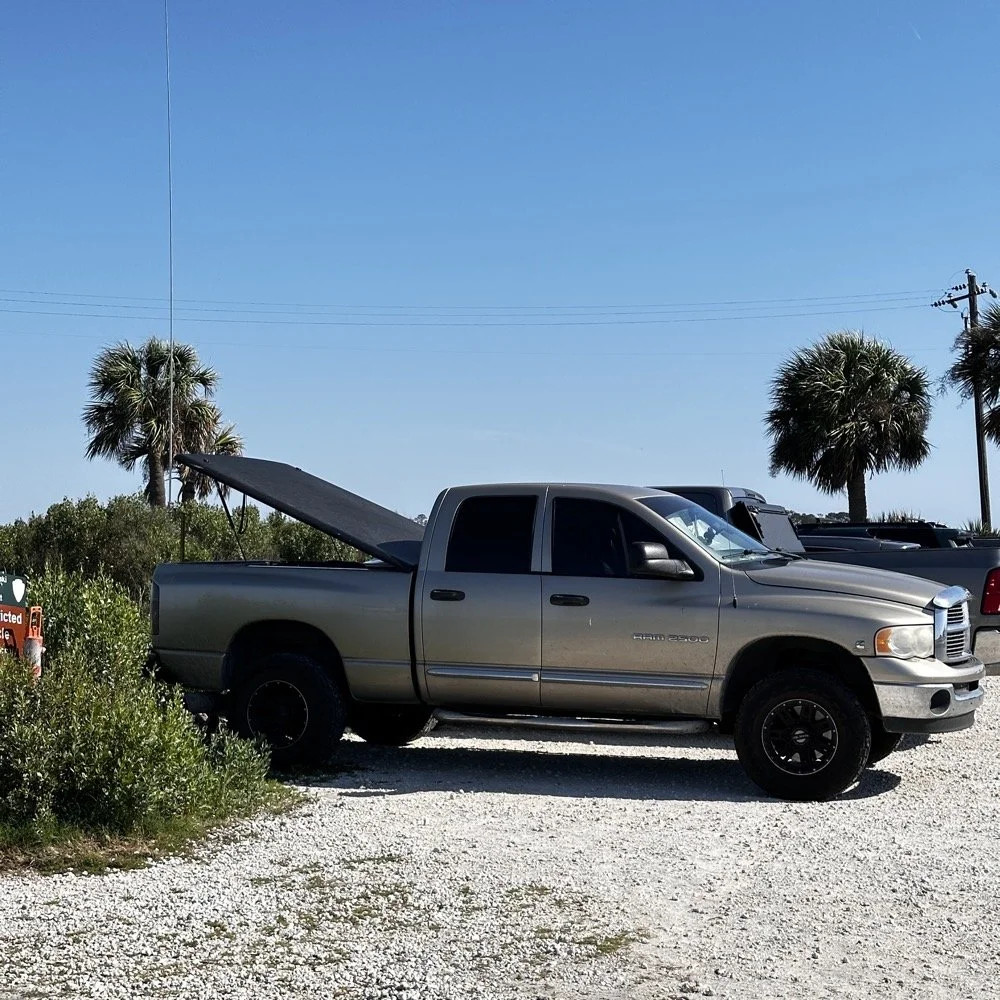
The operating position for POTA
The truck will usually look like this when it is up and operational. I really like operating out of my truck, it is so simple for me now that I have the system dialed in. POTA can look like a lot of things and I find it interesting how each one of us comes up with a unique setup for our uses. I prefer to setup in my truck for a couple of reasons. The main one is that in the summer, I can run the AC and keep cool! The second one is that I can access my truck power as I have a diesel and that means I have two batteries in the truck. I dont run over about 40 watts with any of my POTA rigs so this never depletes the batteries even when I setup for several hours. Plus I can simply crank the truck to recharge the batteries too… win win.
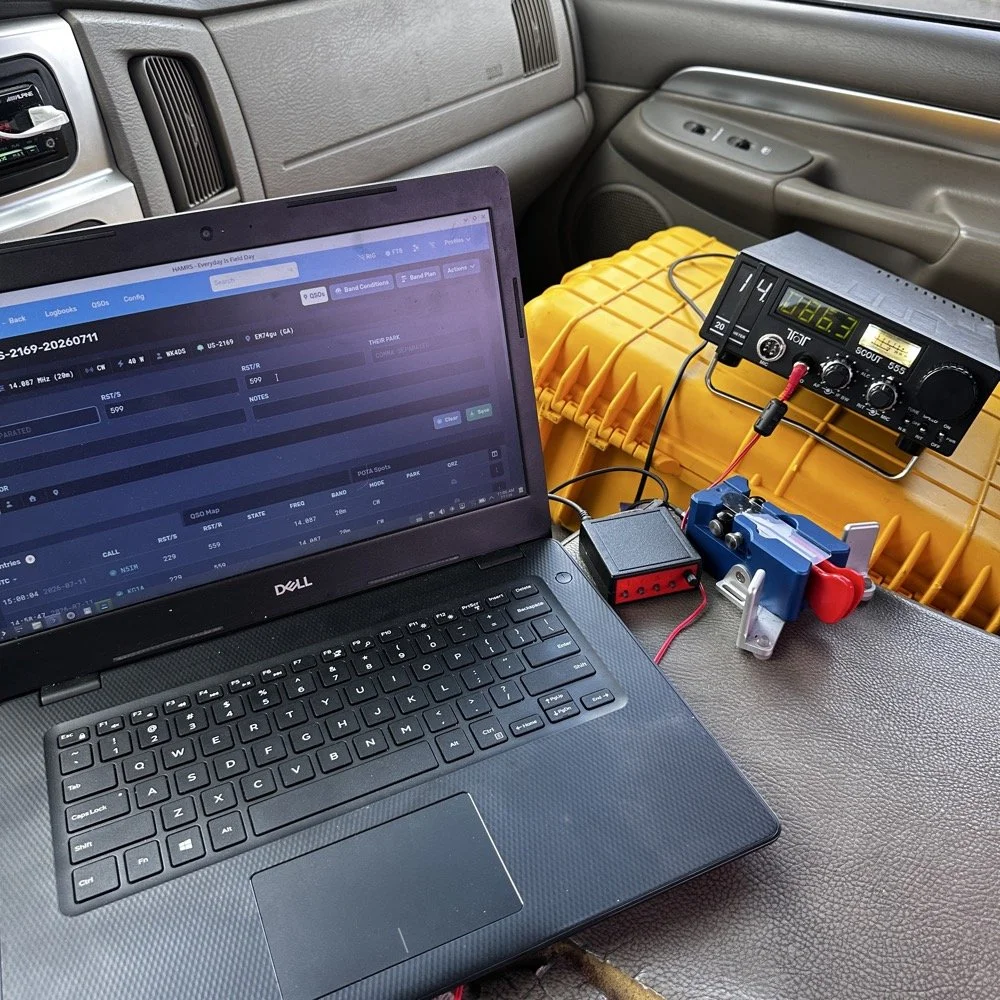
This is the operating position for this day. It looks like this on most days as it is the fastest way for me to get on the air with my POTA rigs. You have the Dell Inspiron computer running Linux Open Mandriva, a Hamgadgets Keyer, the Begali Traveler CW paddle, and the TenTec Scout 555 portable HF radio. This is a solid rig for someone who wants to run SSB or CW and maybe could get this to work with an external sound card for some of the digital modes too. My friend, Roger KG4WHI, has gotten a Scout to do FT8 so i know it is possible.
This was the last band I operated on today. I started on 20 meters, made a dozen or so contacts then moved to 17 meters where I made probably 16 more and then I finally finished with me making 2 on 15 meters if memory serves me right. It wasn’t many, but I was able to get a couple in the log on 15 meters as well. Shoot I was even able to get a Spaniard in the log today. They were weak but I was able to get decent copy on them. It is always a good day when you can add DX to the log on a POTA activation in the USA. You can also see something else in this photo. This is how low I hold the volume when I operate a radio on CW. You want the volume just above the noise floor. This allows you to hear stations that would normally be impossible if the volume was turned up just a little more than this. It is a phenomenon that I learned a long time ago and it is real. It works on any radio too.but you have to wear good headphones for it to work.
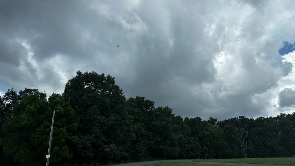
All in all it was a great day with 30 contacts in the log from all over the country and one from the EU. I decided to break the system down as a storm front started to roll in so I would not have to do it in the rain… haha. This turned out to be accurate as it started raining cats and dogs right after I left the park too. That was a close one…
You can help support this channel by using these Amazon Affiliate Links as well:
QRP/Portable Radios:
Antennas & Tuning:
CW Equipment:
Power & Accessories:
Organization & Transport:
BONUS ITEMS (Optional 16-20):
Till next time, I hope you have favorable conditions and the DX is calling! POTA on and 73!
David
WK4DS
Ft Pulaski POTA Activation & Noise
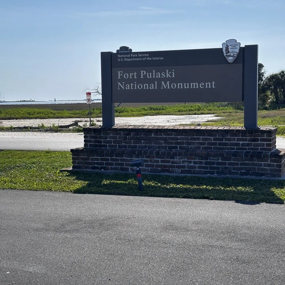
When I went to Tybee Island Georgia recently, I had no idea that I would be within minutes of a POTA park! Ft Pulaski National Monument is park number US-0930 is right outside of town and I was able to get a couple of hours free to ride over and setup a radio to see if I could get my 10 within the window of time I had.
When I went to Tybee Island Georgia recently, I had no idea that I would be within minutes of a POTA park! Ft Pulaski National Monument is park number US-0930 is right outside of town and I was able to get a couple of hours free to ride over and setup a radio to see if I could get my 10 within the window of time I had.
Military POTA park - US-0930 Ft. Pulaski National Monument
When I arrived at the park entrance, I was greeted with a pay station manned by a park employee. The actual fort is across a bridge once you pay the fee…but…there is a loop hole here. You see, the entirety of the park covers way more land than just where the fort is located…way more. The marshland all around the area is also inside the park boundaries. Well, it just so happens that there is about 7 parking spaces OUTSIDE the park entrance! These are for people that want to walk on the footpath that runs along side the road heading out to Tybee Island. The foot path is actually the old railroad bed, but the national park service does a great job of keeping in up for people to ride bicycles and walk on. So I parked in this area for two reasons. One, it is free to park here…and two, it is way faster to setup since I didn’t have to mess with paying to get into the park and then driving to the other side of the bridge to search for a good spot to setup the antenna.
Setting up a temporary POTA radio station
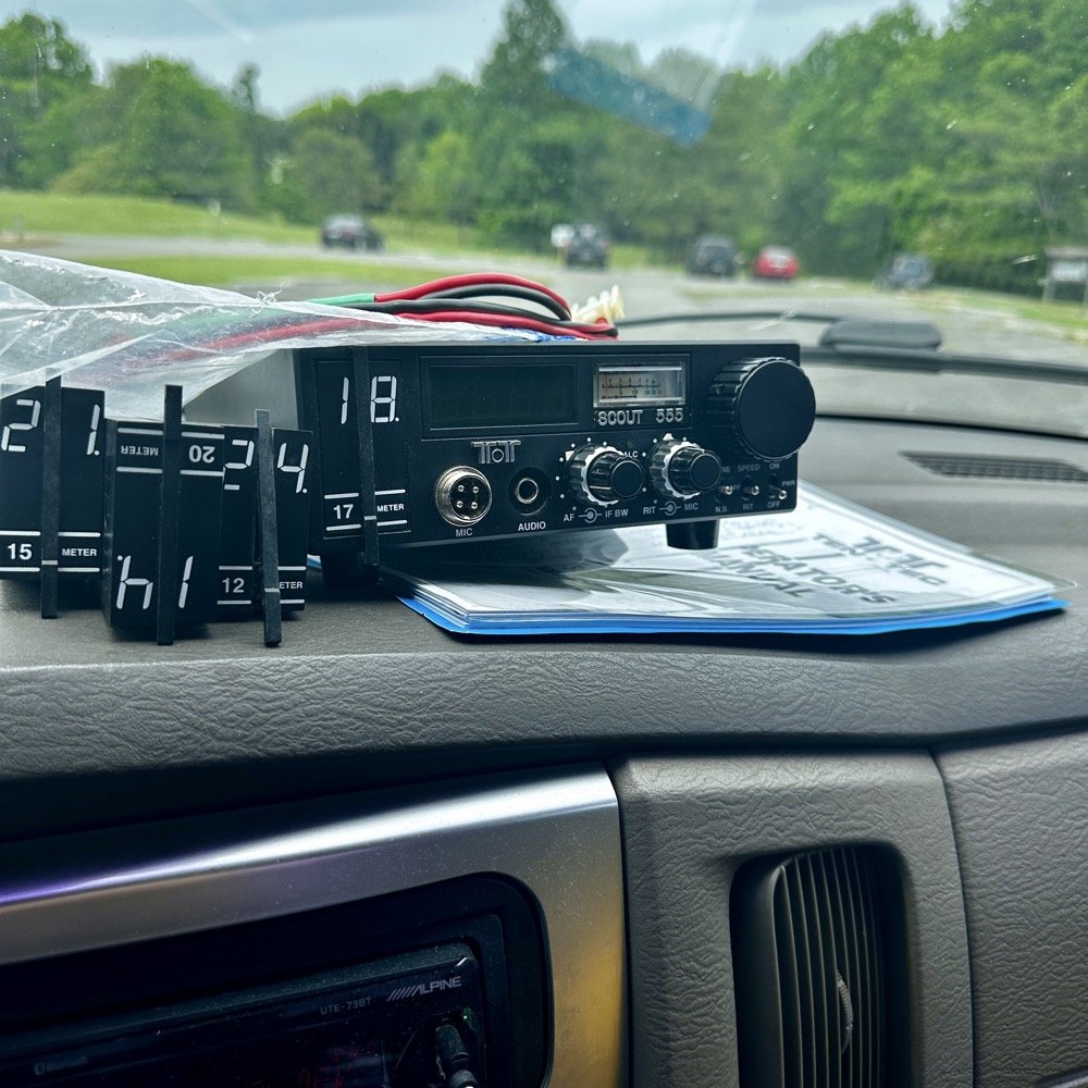
Today I used the 18’ whip and just simply hopped on 20 meters to start with to make sure I got my minimum of ten QSOs in the log before I ran out of time. I had really high hopes for this location too since I am VERY near the ocean here. We all know salt water adds several dB to your signal! haha. See those power lines and that pole in the background? Hold that thought.
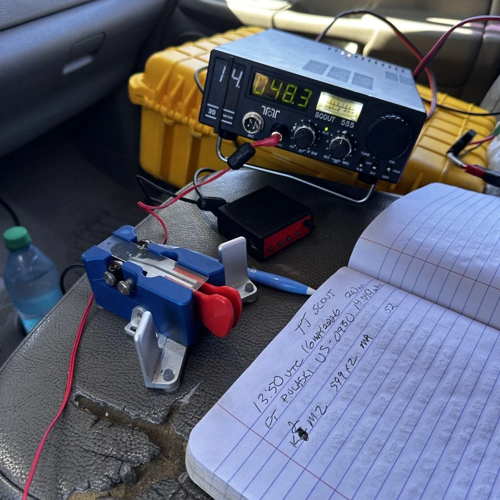
I ran the radio into the cab as usual since I needed the power from the truck to run the radio today. I also didn’t plan on running anything other than the TenTec Scout 555 radio today as I was not sure how long it would take to get the activation in the bag, so I figured I would stick to something I knew would get the job done…CW. It was at this point that I also realized that since I had not planned to activate a park on this short trip that I didn’t bother to bring my logging computer either… dumb, real dumb… It was back to the old reliable paper logbook for this one. I keep a composition notebook in the truck just for this occasion and a couple of pens just in case I forget to bring one of those as well. So I was good to go for logging.
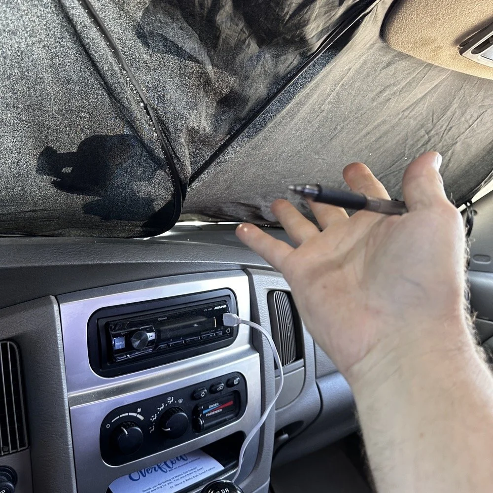
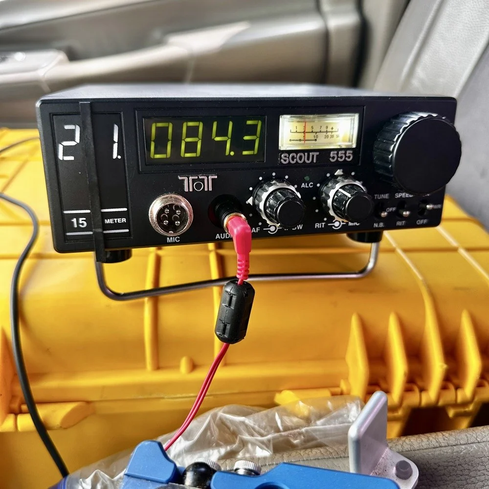
Here is something that a lot of people don’t consider. How to keep the hot sun from baking you alive in your car while activating. I simply put up my window shade and rolled down the windows to let the breeze into the truck and it made it very tolerable. The TenTec Scout 555 amateur transceiver has become one of my all time favorite POTA radios at this point. The simple nature of the design, the excellent CW operation and the novelty of the band modules makes it a lot of fun for me to use. Having the window shade in place made seeing the display on the Scout as well as keeping the heat at bay a good thing.
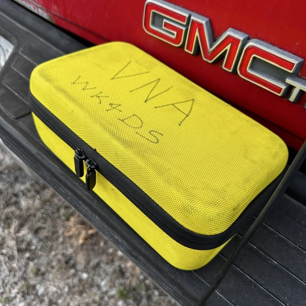
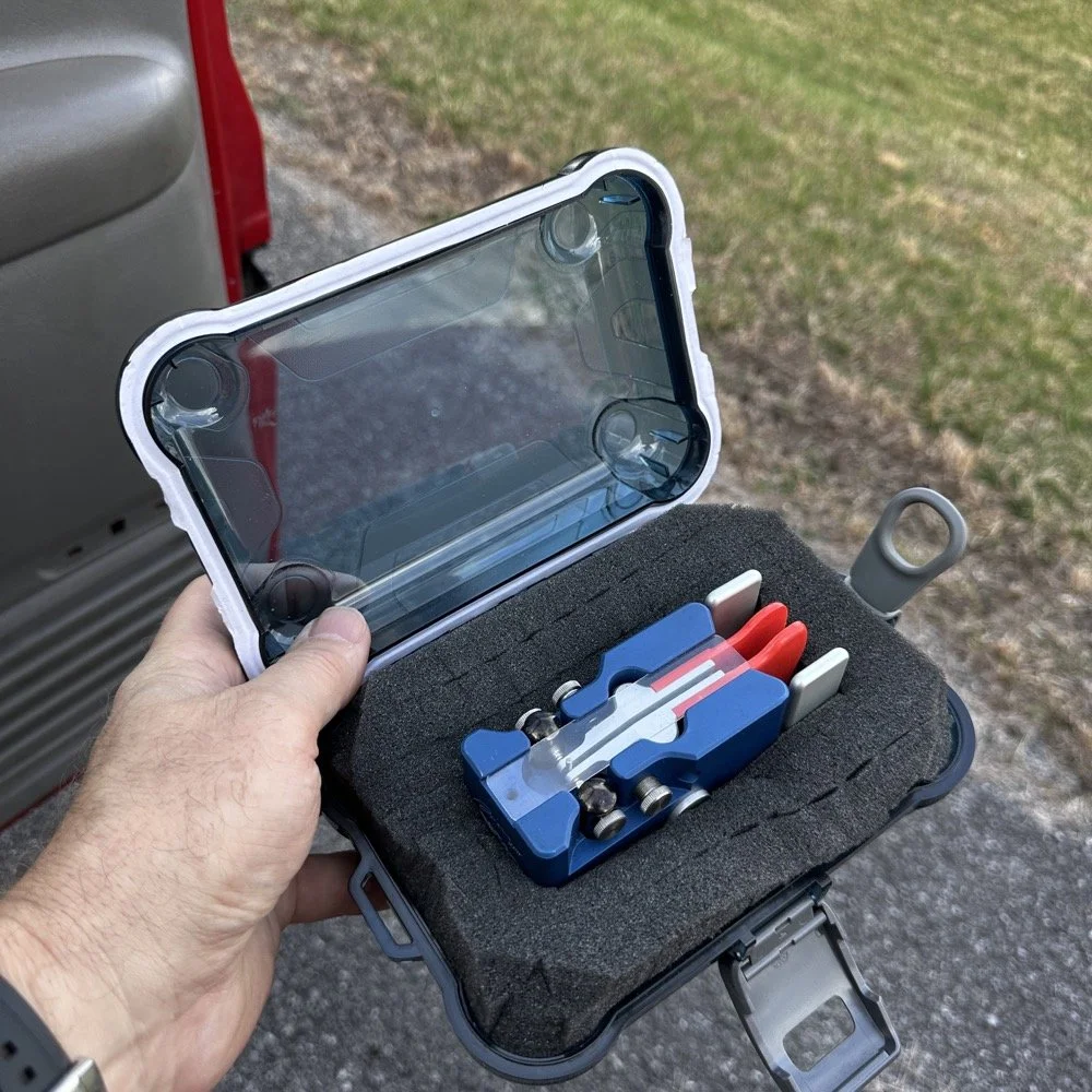
Below you can see how I transport the radio and some of the band modules that I keep in the case with it. At some point I am going to finish adding the one or two missing from the set as I have quite a few in the house so I just need to do it. Also notice the one special one in the case. That 60 meter band module is special. It is the only one on earth that I am aware of at this point. To learn more about it follow this link to see the blog post series where I build this module out of an 80 meter donor module. I keep this radio in a quality hard case to protect it from dust and impact damage as well as water as you can see the water seal on the lid in the photo as well. I also print “field manuals” for all my radios and keep them in the case. TenTec owners manuals have everything you need to keep the radio going, up to an including alignment procedures and a full set of schematic diagrams. Also in the case is the CW memory keyer and under the radio is assorted cables for connecting the keyer and the power cable as well. Another thing of note is the PL259 to BNC adapter that I keep on the radio. This standardizes all my coax cables for POTA to BNC cables only. I don’t run more than 50 watts on my radios so I can use BNC connectors without problems and these work really well. They are fast to connect and break down and work really well. The only down sides I can find are they lack water proofing, and are fragile to some degree as compared to PL259 connectors.
My CW key for today was the Begali Traveler portable CW key. This dual lever paddle key is one of my favorite keys and stays in the truck at all times now. MY N3ZN key that Tony built stays in the camper and I am working on getting that station up and running soon with an EFHW for 80 meters on it. I am hoping that I will be able to get 40, 20, 15 and 10 without much issue as well with that antenna. I have the transformer built, I just need to hang the wire at this point…anyway, enough with that rabbit hole and back to the activation!
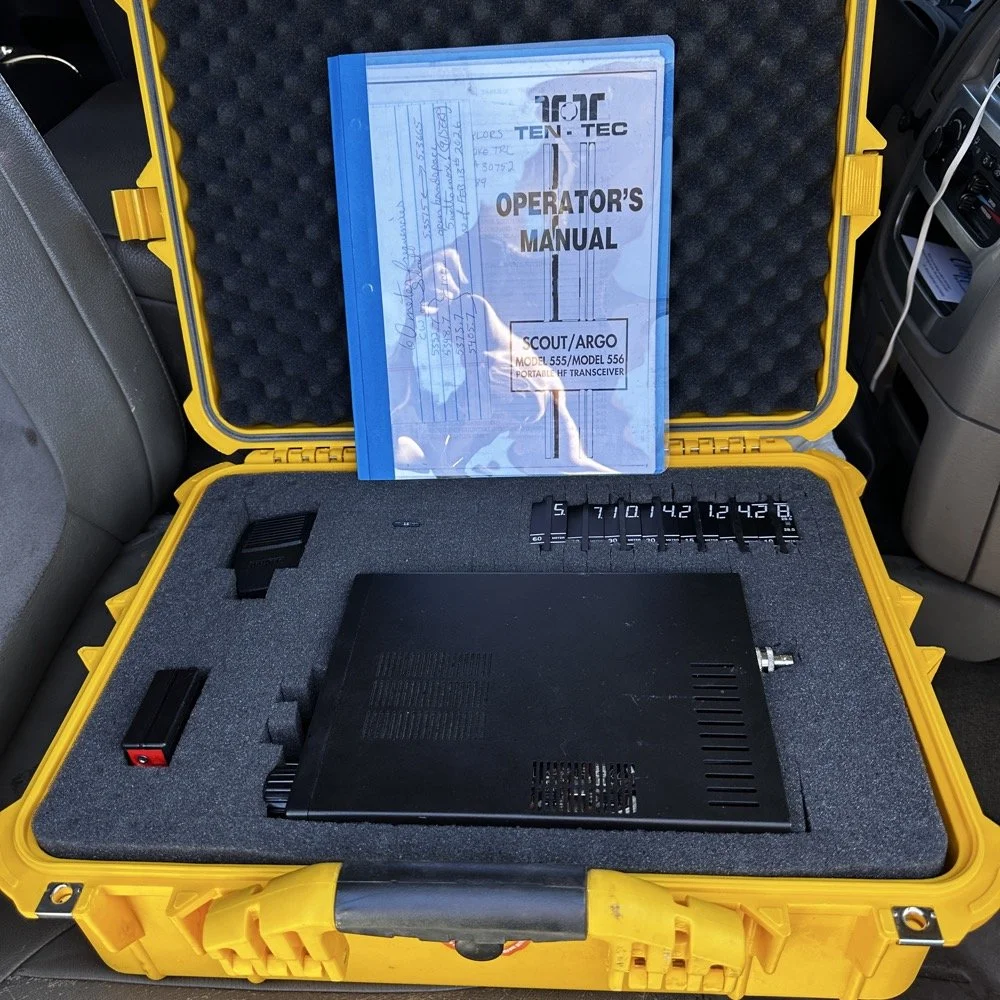
Properly cased TenTec Scout 555 ham radio with hard case.
Solving power line noise on your TenTec Scout 555 ham radio!
The next few photos tell a tale about the power lines you saw earlier in the story. You see, when I powered up the radio, there was this terrible power line noise on the whole band, It was strong too… I was deflated to think that I had went to all this trouble only to be shut down with a bad power line connection nearby… I don’t have an external RF gain control on the radio at all, it is internally controlled by the ALC circuit from what I can tell. So there is no way to remove this noise with RF Gain… The noise was a little over S6 creating a really high noise floor to work with. Then I remembered that this particular radio came equipped with the optional Noise Blanker module installed from the TenTec factory! I flipped the switch and magically the noise just…vanished…
The noise floor dropped a solid 2.5 S units and that made a HUGE difference in my ability to hear weaker stations trying to call me. People will say that an S unit is not a big deal, well it is a big deal when it is measuring band noise! Suddenly stations were coming out of the noise and I could hear them! This was the very first time I have EVER used a Noise Blanker and it actually did the job it was designed to do and help me hear stations on the air.
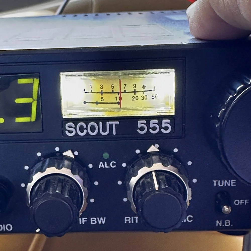
TenTec Scout 555 Radio with Noise Blanker turned off.
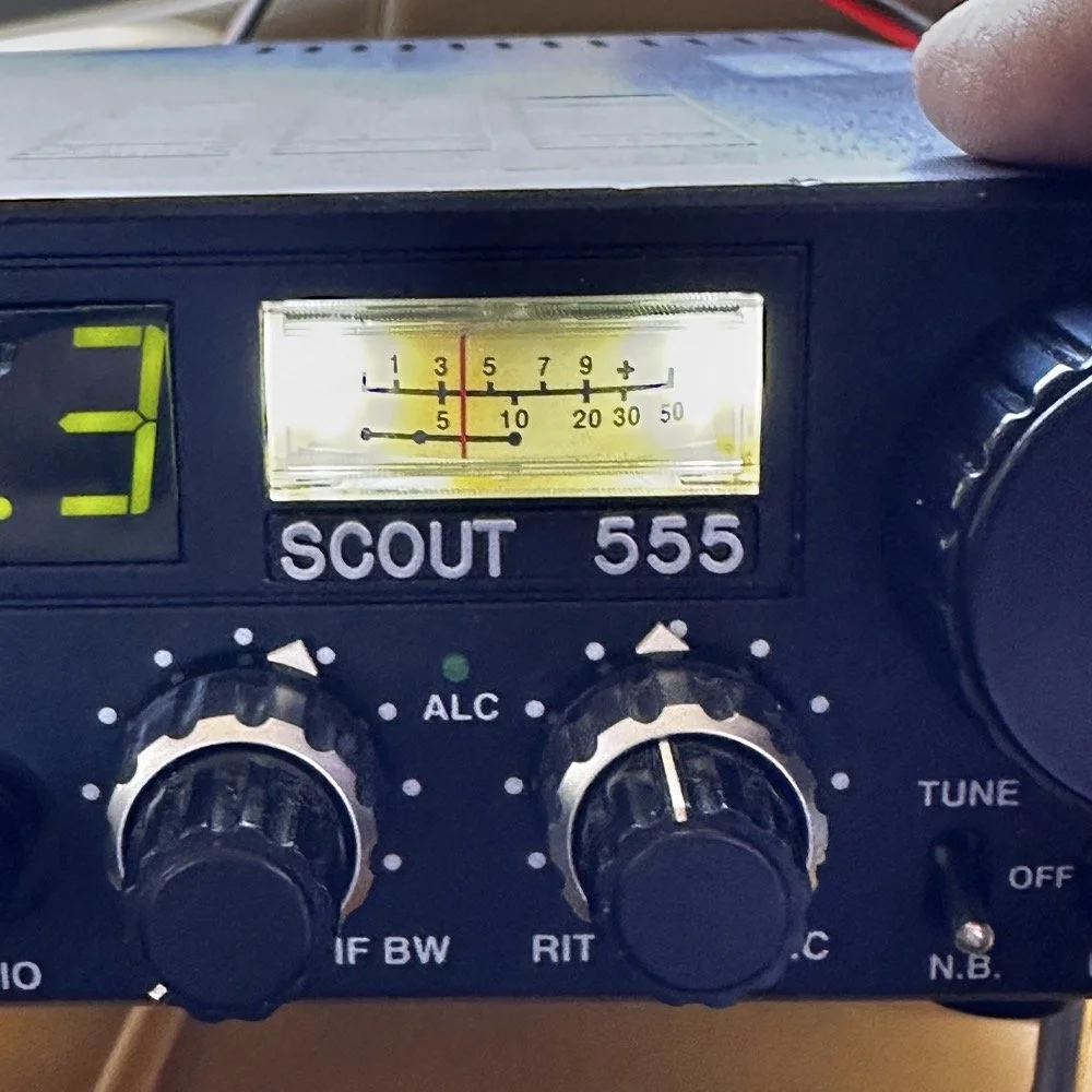
TenTec Scout 555 Radio with Noise Blanker turned on.
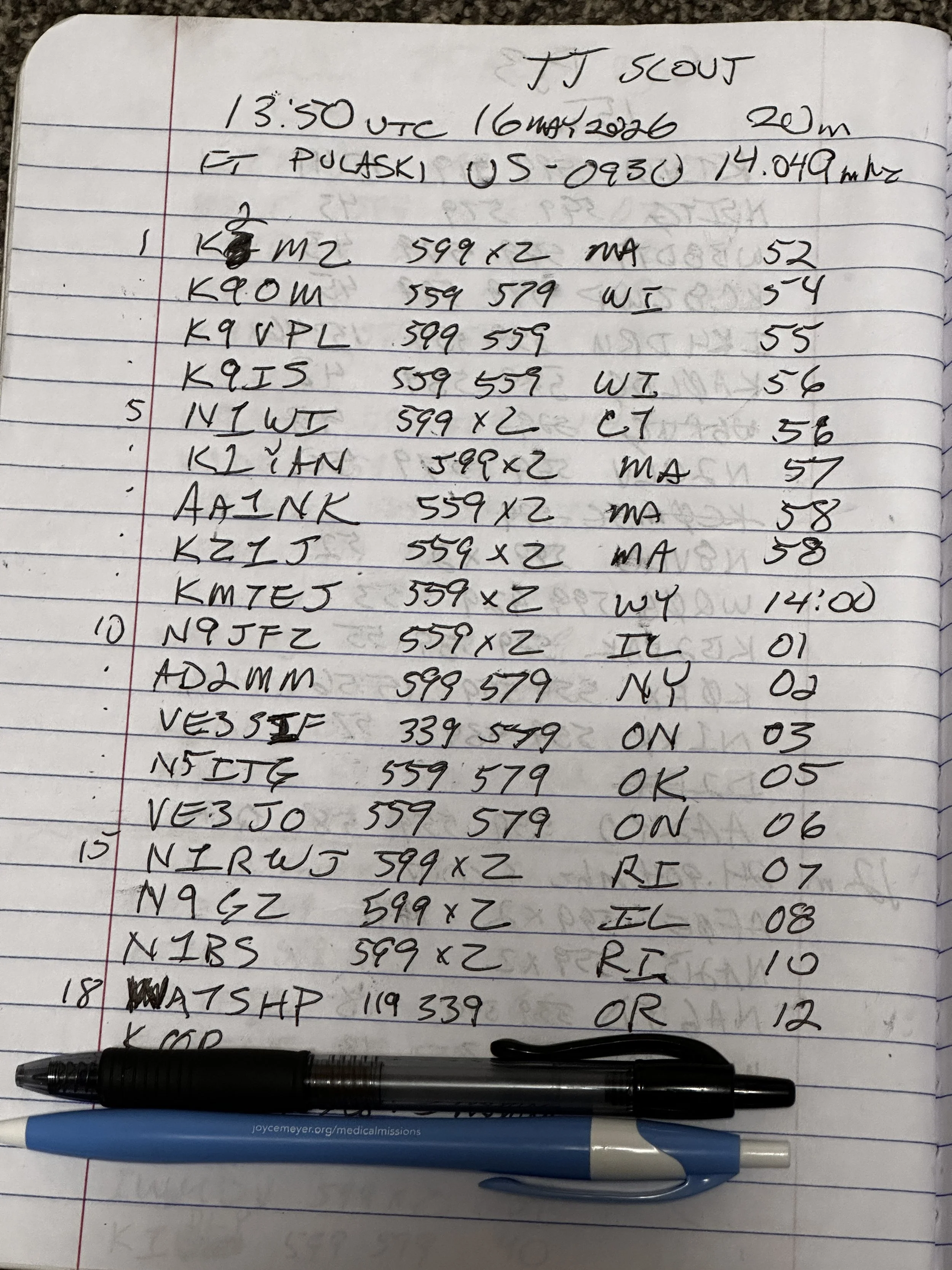
At the end of the day, I had worked 18 contacts, securing my activation and putting several old friends into my log as well. K9IS has been featured in the BLOG a couple of times now and I have many contacts with N1BS as well. It is always great to see callsigns in your log that you recognize. I did attempt 15 and 17 meters before I called it a wrap and packed up but worked exactly zero calls on those bands so I didn’t bother including the page where I just made some band notes and called it quits…lol. Anyway, this is a fun park once you get the noise blanker turned on and I highly recommend it.
Until next time,
73 - WK4DS
You can help support this website by using these Amazon Affiliate Links:
QRP/Portable Radios:
Antennas & Tuning:
CW Equipment:
Power & Accessories:
Organization & Transport:
BONUS ITEMS
Back on the Air for a POTA Activation
Today saw me back at US-2169 for the first time in a while…
Today saw me take the old Dodge over to my local park (US-2169) for a short activation. I have been busy in the machineshop these last few weeks so there has not been much time for POTA. I have actually not been to a park in several weeks and was starting to miss it.
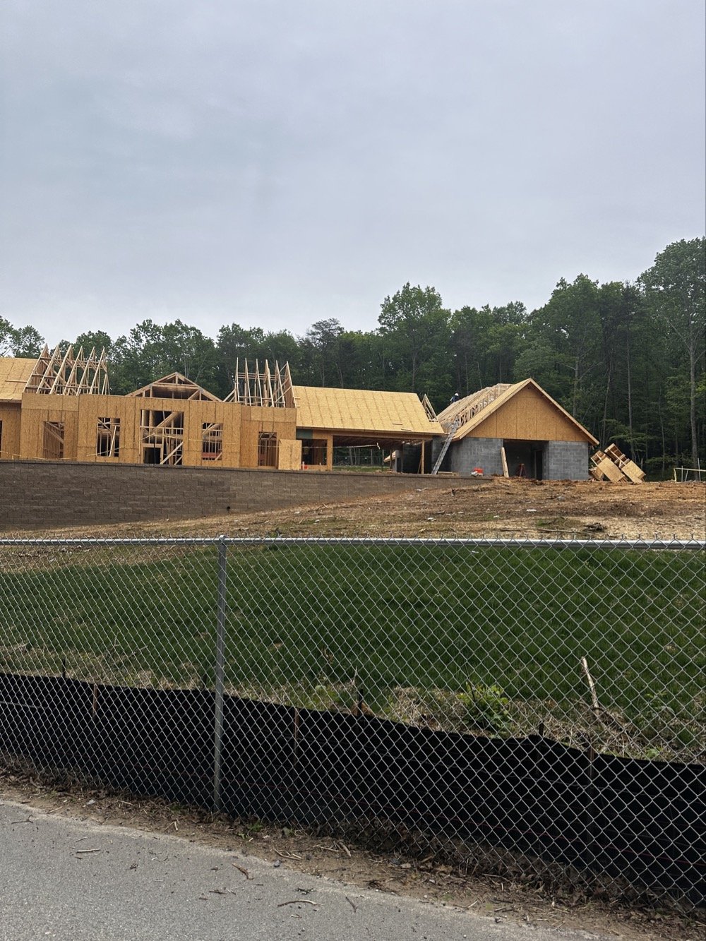
Update on the park visitor center upgrade in progress. The grade work is done and they are framing the new building at this point. It is coming along nicely too.
Setup of my POTA rig for HF operation
I went up to the frisbee golf course again as this is a great place to setup for POTA. A lot of people will use the nearby pavilion when they setup, but my antenna mount, being attached to the truck, makes it alot easier to operate from the truck. This is an amazon 18’4” whip that I bought, you can get one too at this link: Link to 18’4” whip on amazon Now, to just let you know, this is an affiliate link, but it doesn’t change the price from what I can tell… At the time of this writing, they were on sale for 27$, which is incredible!
Today I used the 18’ 4” foot vertical telescoping antenna and two radials attached to the base. Then ran a coax into the cab of the truck to the front seat where I normally set up the radio in the front passenger seat. Something I noticed today was that no matter what band I was on, the SWR plot would never get better than 1.5:1 (which is perfectly fine BTW) but I can normally get way better matches with different radials, which tells me that the radial length is more important that people let on…
Next, I chose the TenTec Scout 555 as it is a wonderful CW machine. It does have a little bit of drift in the VFO, while it warms up, but it is not enough for me to worry about. I started on 20 m in the CW portion of the band and hunted stations to start with. I worked another POTA site for a park to park contact before finding my own space and setting up there. I made 19 CW contacts on 20 m before I decided to move to 15 m to see what I could find there next.
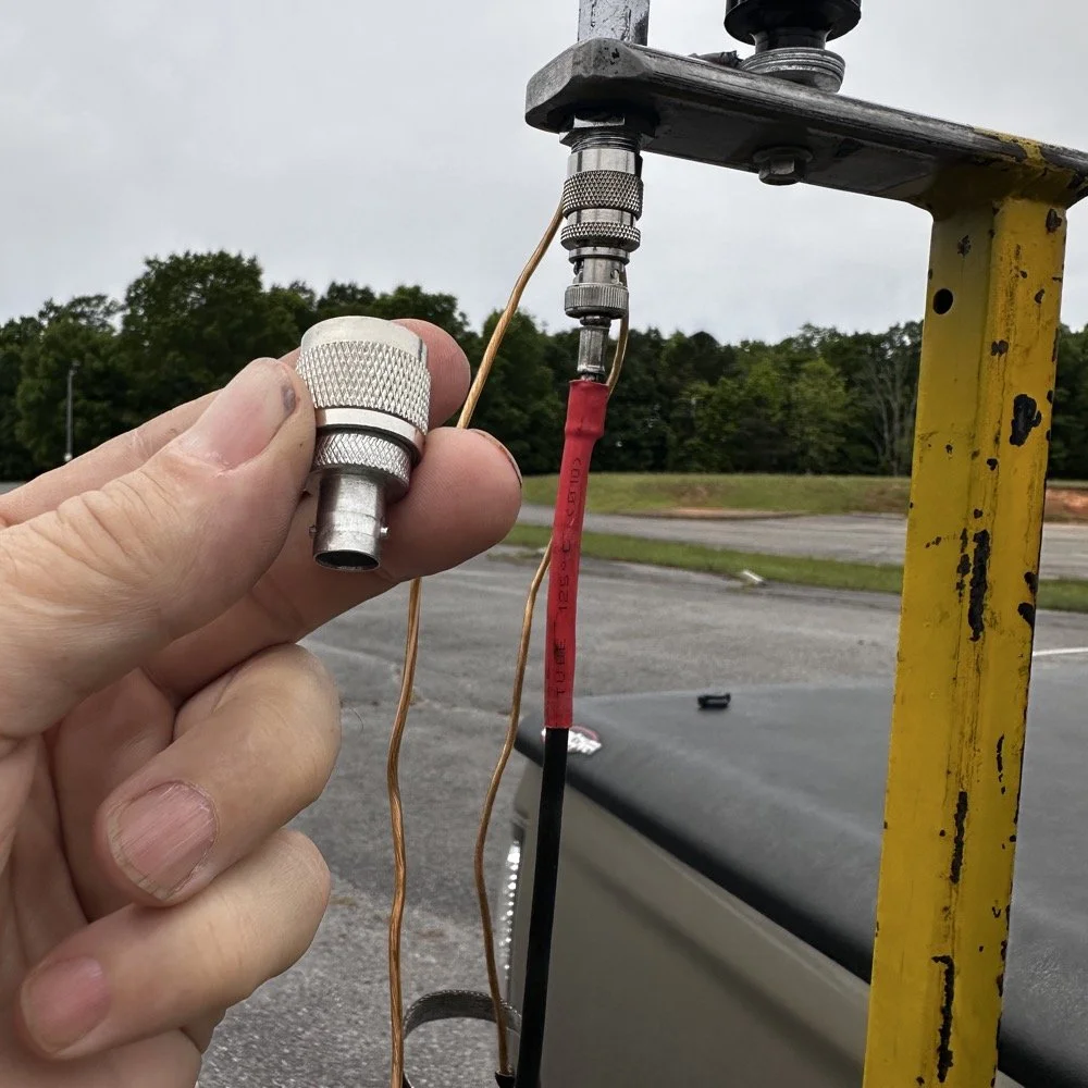
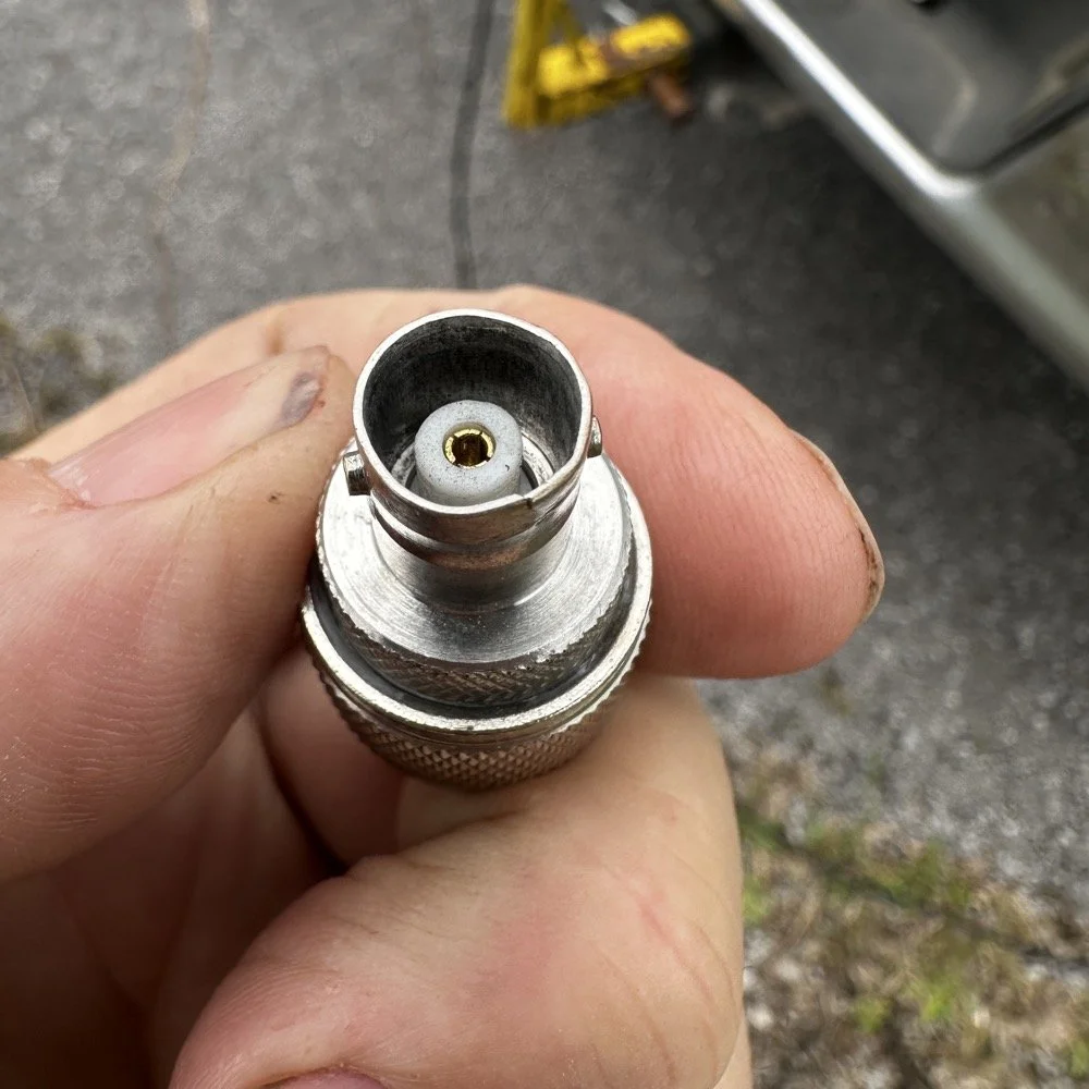
Pay attention to bad antenna connectors…
When connecting the antenna today, I had trouble getting the BNC to attach, upon closer inspection I had found that it was crushed from impacting something in the truck… Probably when it was in the red Chevy as there is less protection in the back of that truck as compared to how I store it in the Dodge. Oh, and yes, my heat shrink tubing on the coax has slipped back for some reason. I noticed it when I was breaking down and simply slid it back into place…haha. I did not notice this until I attempted to use it today to operate this activation.
I attempted to straighten the damaged BNC connector with my Leatherman as best as I could, but it didn’t work really all that well so I got in my adapters for my nano VNA and robbed the one that was in that pack and used it instead.
This is a great example of why you always carry spare parts for all of your connections so that you don’t get shut down because of something getting broken unintentionally that you are not aware of.
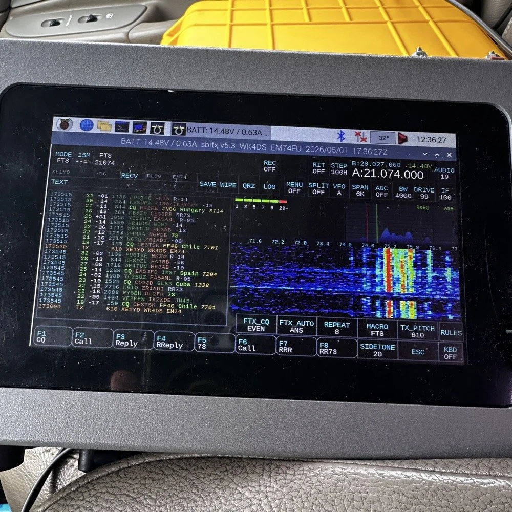
The HF Signals sBitx V3 and native internal FT8
Once I finished working CW on the Scout 555, I decided to get the sBitx out for a while to work some FT8. I really love using this radio for FT8 and CW in parks, it works so well and with the version 5.3 software, it has a metric ton of great features. The waterfall works well and the automatic modes in FT8 are really handy too. This radio is 25 watts on the lower bands and trails off to about 12 watts on 10 meters. This is plenty for me as I work a lot of QRP anyway so little to no power output is fine for the most part. Would it be nice to work with more, yes, but I can manage without it just fine.
Today I only used it for FT8, but I also will use it for CW from time to time. It is a little temperamental in CW since it is a Raspberry Pi 4 running in the background, but once you learn the keying, it works fine up to about 23WPM for me without too much issue. Using something like the Begali Traveler CW Key in the photo below also makes it more fun too. A really nice key is always a good thing to have with you.
Once I worked a few FT8 contacts on 15 meters, I dropped down to 17 meters and worked a few more there before shutting down for the day and heading home.
I noticed when I was getting ready to leave that the truck motor was “squeaking” when it was idling and when I investigated further, I found that it was a pulley on my fan belt had a bad bearing in it. So I went to the auto-part store and got a new one to replace it with. Once home I was able to replace it in short order so that I would be ready for the next POTA outing that I wanted to go on. Sometimes things just come up and you have to take action…haha.
Thank you for following along and I look forward to sharing something with you again soon, till then 73!
You can help support this website by using these Amazon Affiliate Links:
QRP/Portable Radios:
Antennas & Tuning:
CW Equipment:
Power & Accessories:
Organization & Transport:
BONUS ITEMS
Penntek TR-35 QRP power, DX & POTA fun!
Today saw me back in north west Georgia and back at US-2169 (Cloudland Canyon State Park) for a quick little QRP activation. I deployed the Penntek TR-35 QRP HF Transceiver today as it is simple, compact and fun to use…as long as you like CW. This is because it is a CW only radio…haha. One of the things I love about this particular park though, is the fact that it has so many different places to setup a POTA station and not be in anyone else’s way. Today saw me deploy to the top of the hill at the Frisbee golf course (which happens to be my all time favorite place to deploy when at this park) and setup the telescoping vertical on the truck receiver hitch mount that I made. Since this location is in direct sun most of the time, I opted to set the radio up in the cab.
Cloudland Canyon State Park - US-2169 POTA Destination
Today saw me back in north west Georgia and back at US-2169 (Cloudland Canyon State Park) for a quick little QRP activation. I deployed the Penntek TR-35 QRP HF Transceiver today as it is simple, compact and fun to use…as long as you like CW. This is because it is a CW only radio…haha. One of the things I love about this particular park though, is the fact that it has so many different places to setup a POTA station and not be in anyone else’s way. Today saw me deploy to the top of the hill at the Frisbee golf course (which happens to be my all time favorite place to deploy when at this park) and setup the telescoping vertical on the truck receiver hitch mount that I made. Since this location is in direct sun most of the time, I opted to set the radio up in the cab.
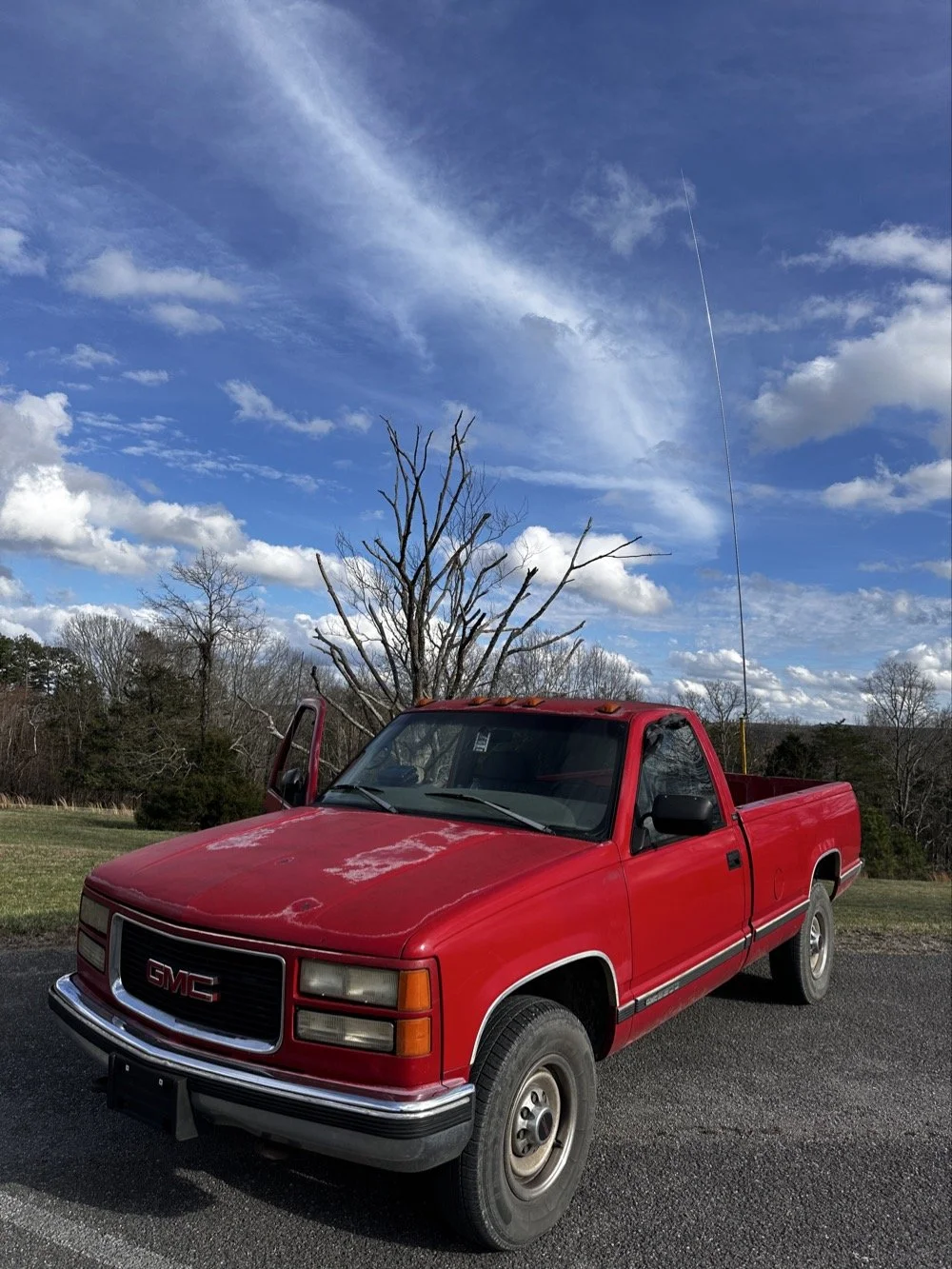
The old red chevy is back in service as the War Wagon is down currently with several problems. Today saw me setup the 18.4’ telescoping vertical from Amazon.
Setting up the 18.4’ Telescoping Vertical Antenna on 20m
Tuning is simple with my old friend the nanoVNA. I have learned to simplify my tuning process to the following. I will setup the antenna and collapse the first section at the top as it never ends up being needed unless I go below 20 meters. Then I deploy the two usual radials and connect them to the ground lug on the antenna base. Then I connect the nanoVNA to the base of the antenna with a short coax jumper and power on the nanoVNA. I have mine set to power on with the span set from 1mhz to 30mhz and you will immediately see the null where the antenna is tuned somewhere in the middle. Then I choose the menu for the marker and set the marker to minimum and then check the “tracking” box so it will follow the null. When you do this, the marker will display the center of the tuned frequency at the top of the nanoVNA. Now all you do is start shortening the antenna a little at a time till the frequency moves up to about 14.050mhz and your done! I happen to be just tall enough to be able to reach to first collapsible section on the antenna while it is still mounted and I can simply slide it down a little at a time without having to take it down to do it. This whole tuning process takes maybe two minutes now that I have done it so many times. It goes really fast. With the antenna built and tuned to 20 meters CW (today I couldn’t get the SWR below 1.5:1 for some reason but as you will see later, that is not a problem), I turned my attention to the radio side of the build out…
The GigaParts soft shell case is a great way to store a nanoVNA and all the cables and adapters you will collect for it.
Quick side note… I have FINALLY bought a hardshell case for my Begali Traveler CW paddle! I found this little case at Walmart if I remember right and the foam was left over from the Harbor Freight hard shell case for the Scout 555 I bought recently. I guess it pays to hold on to the scraps on occasion…haha. I have about gotten to the point where I dont save stuff like this foam, but for some reason I held on to this one. I really love this key and it have become the de-facto key I use as long as I have a hard surface to sit it on. I have retired my N3ZN key that I got from Tony a while back to my camper key and it now lives with my TenTec Argonaut V permanently in that capacity. I still deploy with three keys most of the time and if I don’t bring the Penntek TR-35 then I will have two keys. I will get into all that later, but for now, lets keep setting up the radio.
I finally procured a storage solution for my Begali Traveler CW paddle so it doesn’t get damaged between POTA park activations.
Pros and Cons of the Penntek TR-35 QRP Transceiver
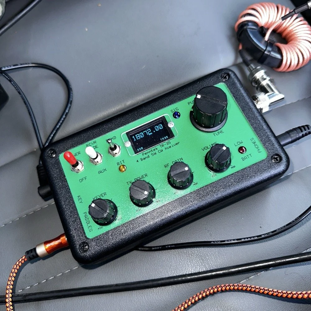
Below is the star of the show…the Penntek TR-35 4 band QRP HF Transceiver. This little radio sports the following features which make it perfect for POTA field ops.
It is small and light weight.
Output power is a full 5 watts and adjustable down from there.
Three filters he calls SSB(VERY wide), CW wide and CW narrow. I think CW narrow is 500hz or a little less as it is really selective.
Two keyer memories that are easy to program once you get the cadence down.
4 HF bands (40m, 30m, 20m, & 17m) The radio only toggles up through the bands with the band switch. Simple and effective.
RIT which is de-facto split if you need to work a split station. It also helps me when someone is off a couple hundred hertz as well.
VFO has three speeds for the tuning. The default two are past the decimal and a long press on the VFO will set it to 1 khz tuning which is really fast for the CW portion.
There is a physical RF Gain AND a Volume knob!!! That is awesome on a whole different level by itself.
The keyer speed is set by a knob so speed changes for different POTA hunters is easy and fast. I really like this feature.
It has a straight key input as well as a paddle input so you are ready to go with either kind of key.
Some detractors that I wished were different are…
I really wished it had 15 meters instead of 17 meters…but I digress…
It is so small that there is no room for a speaker so you must use some sort of external speaker whether it be earphones or something like what I used today.
It lacks an S meter and this bothers me so much that I built one just for it. Link is here to that article…
That is about it for what I dont like, it is almost perfect.
The Penntek TR-35 HF QRP transceiver is almost perfect, it is so close I wouldn’t change it now if I could. It really has everything you need and nothing you don’t to run a POTA activation.
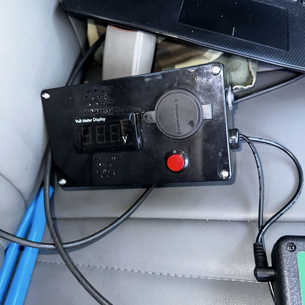
Homebrew power pack containing a Bioenno 3Ah LiFePO4 battery, speakers and a "on demand" voltmeter with a pair of Anderson power pole connectors
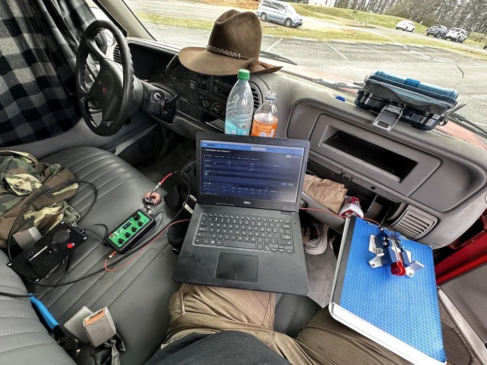
This is the station for today. Dell Inspiron computer, Begali traveler paddle, Penntek TR-35 QRP radio, and a POTA park!
POTA Station Positioning and Start Up
Once I finished connecting all the RF equipment together, I had to figure out where I would sit. I had not really considered this as my regular truck has that huge, flat arm rest that I normally have access to. With that considered, I decided to setup in the passenger seat as this made the most logical sense. Then I had the problem of the sun causing me a ton of glare and I had to come up with something to mitigate it. The below photo is my expedient “curtain” that I simply rolled up in the window. Modern problems call for modern solutions… lol.
Once the sun was beaten back out of the cab of the truck, I had to figure out how to setup up the whole station so that I could send code and log the contacts as well. What you see is how I solved that problem, I just balanced the computer on one leg and the clip board is cheated. The clip board is actually sitting on the top of the open glove box, which is stabilizing it, and then it is making the third contact on my leg which turned out to be very stable for the cw key. The Begali Trraveler is one of those keys that once you get it set like you want, it is simply a dream to use. I have learned that it takes me a few minutes to get it positioned properly or I will make a lot of mistakes with it. But once I get it in the right spot, it just works.
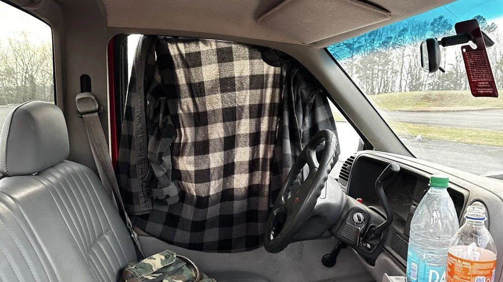
Simple problems require simple solutions, this is how I removed the sun glare off of my radio and computer screen today. If it works…
Activation Report: The Penntek TR-35 and 5 watts of RF Power
Once I had the station sorted out, I powered up the rig and hunted me a clear frequency, today the 20 meter band was going strong so the band was a little crowded. I would call QRL (This means “Is the frequency in use?”) and I would hear a lone “R” come back to me. This means someone is using it so I would simply dial to another frequency and try again. I finally found a clear spot and listened for a bit as sometimes you are on the other side of a station that is talking to someone you can not hear and they are listening to them at the time you get on frequency. So it is a good idea to listen for a while before sending QRL to make sure this is not happening. I didn’t hear anything and after calling QRL again, I started calling CQ POTA… Then things took off…
The log for this activation came together really nicely, and I was pretty happy with how the bands cooperated. All 36 contacts were CW at 5 watts QRP from US-2169, split between 20 meters and 17 meters.
I started on 20m at 14.061 and the pile-up got going almost immediately. The contacts came in steadily from all over the place -- Illinois, Vermont, Michigan, Missouri, Maryland, North Carolina, Texas, and more. A couple of Canadian stations made it into the log too, with VE3UXJ and VA3EKR both pulling through with solid enough signals to complete the exchange. Signal reports on 20m were mostly in the 559 to 599 range, which honestly is about as good as it gets when you are running 5 watts into a field antenna. Also remember that this radio lacks that S meter I like to have…so the signal reports were a bit more subjective today compared to other days.
After working through the 20m pile-up, I switched over to 17m at 18.072, and that is where things got really interesting. The band was in good shape with minimal QSB and the contacts kept coming. It did take a few minutes of calling CQ to get the RBN (Reverse Beacon Network) to auto update my spot on the spot page of the POTA website, but once it did, things started looking up! I picked up stations from Idaho, Florida, Colorado, Washington, and Texas, among others. But the two that really stood out were HI8D out of the Dominican Republic and JH1OCC from Japan! Getting Japan in the log on 5 watts from a field activation is always a treat, and the fact that JH1OCC came back at all through the noise is a testament to how well 17m was performing this afternoon. His received signal report was a 339, which is pretty typical for a trans-Pacific path at QRP, but a contact is a contact and I will absolutely take it! This has happened to me a few times now while doing POTA, I will be on one of the upper bands and a band opening to the Far East will open up for a couple of minutes and I will land one or two Japan calls. It takes me a minute to process this sometimes, as it is a long way to Japan from NW Georgia!
Total QSO count landed at 36, which is a solid activation by any measure. Both bands contributed meaningfully, and the geographic spread across the log -- from the Midwest out to the Rockies, up into Canada, down to the Caribbean, and all the way to Japan is one of those things that never gets old no matter how many activations you do. Five watts and a wire…errr…vertical…lol…, doing its thing. This setup worked pretty well but if I could improve it, I would make a more steady surface for the key. The key moved around too much for my liking so I would like to correct that going forward, like maybe use a different key…lol. Anyway, it was a great day in the park and I hope this nudge you to get out and activate a park near you.
You can help support this website by using these Amazon Affiliate Links:
QRP/Portable Radios:
Antennas & Tuning:
CW Equipment:
Power & Accessories:
Organization & Transport:
BONUS ITEMS
73, David / WK4DS

Ten watts to Spain. Ten watts to Germany. Ten watts to Austria. The EFHW at 35 feet made all the difference.
Activating Hillsborough River State Park (US-1878) with a friend is one thing—making over 100 contacts in a single afternoon using QRP power and a homemade wire antenna is another. That's exactly what Chas and I accomplished using a 65-foot EFHW antenna strung 35 feet up in the Florida pines, a ground mounted vertical, his FT891, a Penntek TR-35, and my sBitx v3 running just 10 watts (Chas was running 50 watts today though). This wasn't just a Parks on the Air activation—it was a field test of how well minimalist gear performs in a multi-operator setup, complete with lessons learned about antenna placement, front-end overload, and working around the Florida sun.
Activating Hillsborough River State Park (US-1878) with a friend is one thing, making over 100 contacts in a single afternoon using QRP power and a homemade wire antenna is another. That's exactly what Chas (NA2B) and I accomplished using a 65-foot EFHW antenna strung 35 feet up in the Florida pines, a ground mounted vertical, his FT891, a Penntek TR-35, and my sBitx v3 running just 10 watts (Chas was running 50 watts today though). This wasn't just a Parks on the Air activation, it was a field test of how well minimalist gear performs in a multi-operator setup, complete with lessons learned about antenna placement, front-end overload, and working around the Florida sun.
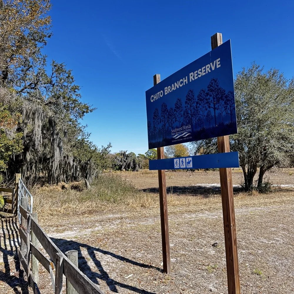
Hillsborough River State Park entrance designated K-1488 for Parks on the Air activations.
Hillsborough River State Park: Location and Access
Hillsborough River State Park sits about 12 miles north of Tampa and makes for an excellent POTA location. When you arrive at the entrance, the first thing you're greeted with is a ranger station where you pay your four dollar entrance fee. Yes, you read that right—four dollars for the whole day. This is a really nice park with extensive hiking trails, a large loop perfect for biking, and the Hillsborough River running through it where visitors can enjoy boating and fishing.
There's plenty of infrastructure here for families… playgrounds, picnic areas with covered pavilions, and well-maintained facilities. For POTA activators, the key feature is the abundance of tall trees throughout the park, making it ideal for wire antennas. The main loop road has several pull-off areas with picnic tables that work perfectly as operating positions. Cell phone coverage is good throughout the park, which helps for spotting yourself on the POTA network and coordinating with other operators.
After paying the entrance fee, I drove around the loop a couple of times while talking to Chas on the phone, trying to figure out where he'd set up. Here's the kicker, though, he decided to drive over to my location so we could operate together from adjacent tables. This gave us the multi-operator experience but also taught us some valuable lessons about antenna placement and RF interference, which I'll get into later.
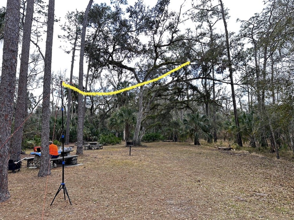
The 65-foot EFHW antenna strung into the tree canopy (highlighted in yellow) getting the wire 35 feet high made a dramatic difference in propagation. The wire itself is nearly invisible against the tree background.
The Antenna Setup: 65-Foot EFHW in the Trees
Today saw the use of a 65-foot long wire antenna, an End-Fed Half-Wave from Reliance Antennas. This antenna isn't rated for high power, so I held all of my transmit power to 10 watts or less throughout the day to prevent potential damage to the matching transformer. We deployed it using throw lines to get it about 35 feet up into a large oak tree, then Chas loaned me his 10-foot push-up pole and stand to support the feed point end of the antenna and get it a little higher off the ground as well.
I believe this additional height aided propagation dramatically. Getting the whole 40-meter EFHW that high off the ground, with the far end even higher in the tree, made a noticeable difference compared to previous activations where I'd run antennas lower. I made many contacts all over the United States, into Mexico, and even worked some European stations on the higher bands with just 10 watts. That's the magic of getting a wire antenna up high… height matters more than power in many cases.
The EFHW is resonant on 40m, 20m, 15m, and 10m without needing an antenna tuner, which keeps the station setup simple. I specifically avoided the WARC bands (30m, 17m, 12m) during this activation because the antenna isn't cut for those frequencies and I didn't want to deploy a tuner. Sometimes keeping things simple is the better approach, especially when you're testing equipment and learning how gear performs in the field.
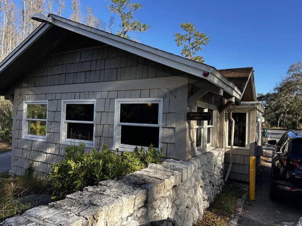
The ranger station where you pay the $4 entrance fee to access the park for POTA activations.
Radio Gear: Penntek TR-35 and sBitx v3 Performance
Once I had the antenna set up and tested, I decided to use the Penntek TR-35 transceiver first. I really enjoy using this tiny little radio, the CW break-in is phenomenal, and the keying from the internal keyer circuit works flawlessly. It's a true QRP radio putting out 5 watts maximum, and I've made some additional accessories for it to turn it into a more complete field station. But even as it sits stock, it's a wonderful little radio that's almost impossible to damage from bad antennas or other field mishaps. Plus, it just works really well at making contacts.
I started on 40 meters and after working through a good run of stations, I decided to move up to 20 meters where activity was heating up. Chas started on 30 meters and worked his way through the WARC bands, eventually ending up on 10 meters where we made a park-to-park contact with each other from 30 feet apart. That was pretty funny, logging a P2P (park-to-park) contact when we could literally see each other across the operating area. I turned my output power all the way down, it showed literally zero output and I was still booming into Chas’ radio!!! Haha!
After finishing my run on 20 meters with the Penntek TR-35, I swapped it out for my sBitx v3. I throttled the output power on the sBitx for two reasons: first, to prevent damage to the antenna which isn't rated for high power, and second, to keep from running down my battery too quickly. I'd brought an 8 amp-hour LiFePO4 battery, and if I'd run the sBitx at full output power I could have easily depleted that battery in an hour or so, especially running FT8 on the lower bands which requires more transmit time. As it turned out, limiting power to 10 watts kept the battery happy all day and I still had plenty of capacity left when we packed up.
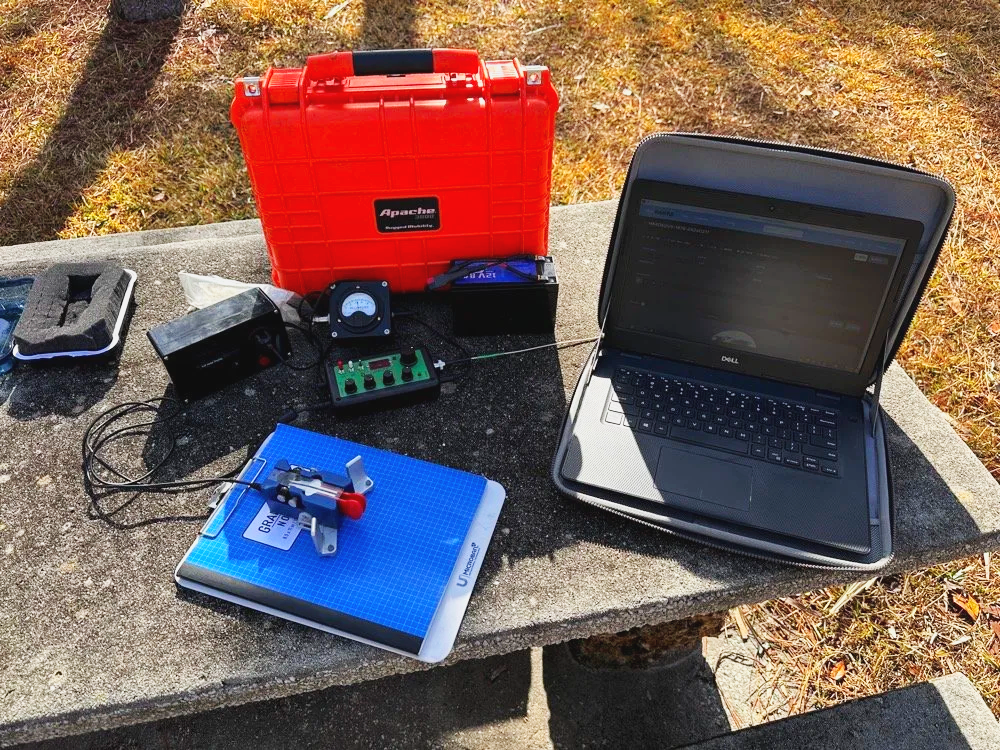
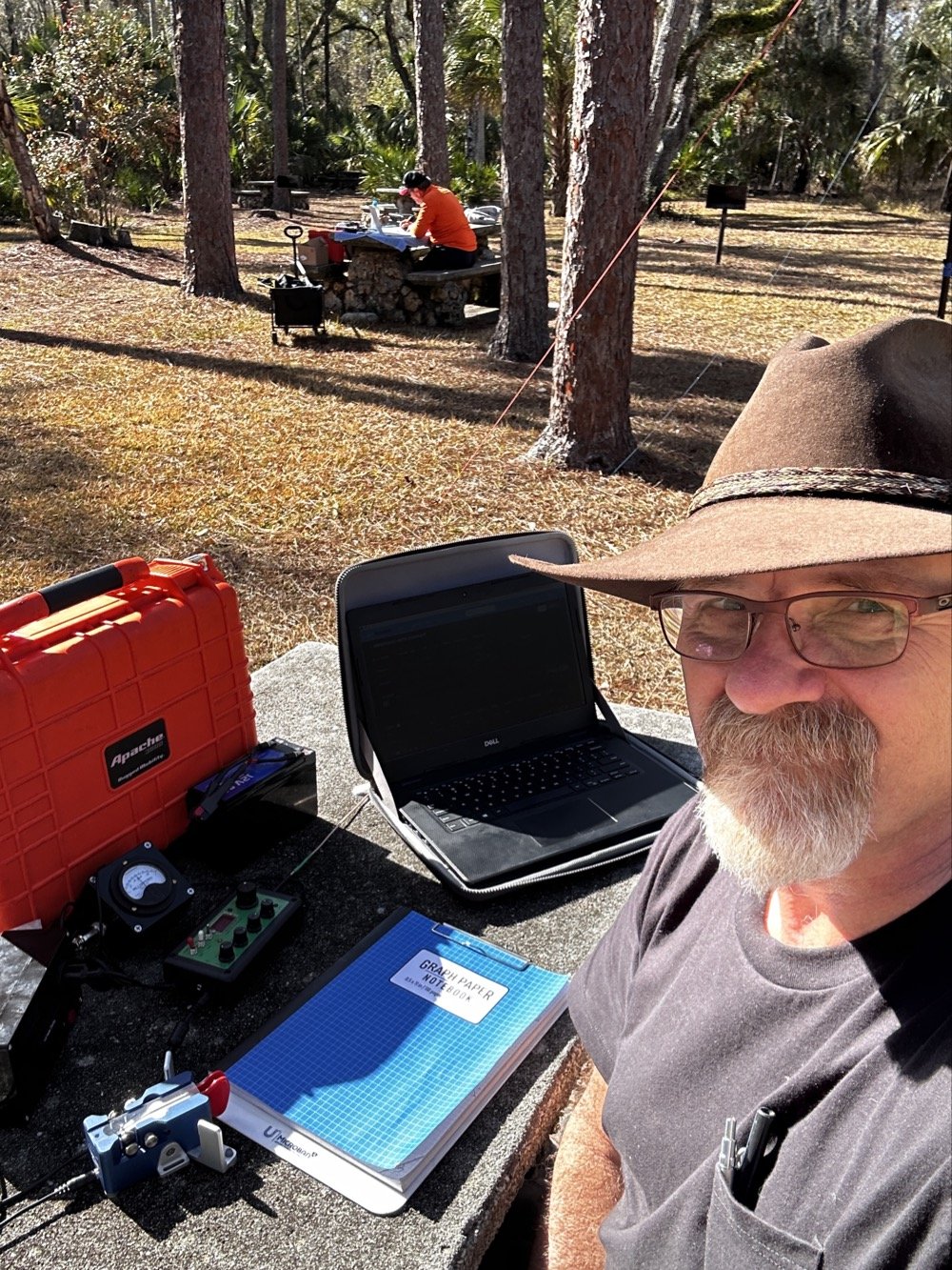
Initial station setup with the Penntek TR-35, Dell laptop for logging, clipboard with paper log, and CW paddle ready to make contacts.
The first thing I did with the sBitx was get on 15 m and attempt to make contacts there on FT8. This went pretty well and I made several contacts on 15 m before moving to 10 m to see what I could make on that band. The reason I skipped the WARC bands today was because this antenna is not resonant on any bands other than 40, 20, 15, and 10 m. So I stayed on those bands as I did not want to try and deploy an antenna tuner as well.

The sBitx v3 with improvised sunshade, Florida sun glare was a constant challenge throughout the activation. Notice the notebook to keep my arm off that rough concrete!
Contact Statistics:
Between Chas and me, we logged 118 total QSOs during the activation! 66 in my log and 52 in Chas's log(I did operate a little longer than him and we were not in a race either). Here's my detailed breakdown:
David's Stats (WK4DS):
40 meters: 5 QSOs (all CW)
20 meters: 50 QSOs (all CW)
15 meters: 1 QSO (CW)
10 meters: 10 QSOs (8 FT8, 2 CW)
Total: 66 QSOs
CW: 58 contacts
FT8: 8 contacts
Geographic Breakdown:
Domestic (USA): 56 QSOs across the continental United States
DX (International): 10 QSOs reaching six countries:
Spain: 2 contacts (EA4T, EA5BCO)
Germany: 2 contacts (DL4JCP, DJ9HX)
Mexico: 2 contacts (XE2BCS, XE2IF)
Austria: 1 contact (OE2IGP)
Canada: 1 contact (VE1ZZ)
Poland: 1 contact (SQ9JS)
Czech Republic: 1 contact (OL26WRTC - special event station)
NA2B Chas's Stats: Chas logged 52 QSOs throughout the day, primarily working 30m, 17m, and 10m (he might have done more but that is all I know of) while I focused on 40m, 20m, 15m & 10m. This band coordination helped us avoid stepping on each other while maximizing total contacts for the activation.
Combined Performance: For QRP power (my 10 watts maximum and Chas running 50 watts) and simple antennas, 118 total contacts in one afternoon represents excellent POTA performance. The 10 DX contacts on 10 meters with just 10 watts and the EFHW antenna particularly stand out, working Spain and Germany on FT8, then switching to CW for additional European contacts, demonstrates what's possible when propagation cooperates and you get your antenna up high.
Twenty meters was the workhorse band, delivering 50 contacts in my log alone. The concentration of activity on 20m CW (14.061 MHz) is typical for POTA activations, as this is where most hunters are listening for parks. The handful of 40m contacts at the start of the activation caught the tail end of daytime propagation before that band shifted to primarily short-skip domestic contacts.
Operating Challenges - Sun and Glare
Both Chas and I learned pretty quickly that the Florida sun was not our friend today, even though the temperature was pleasant. The glare from the sun continuously made us struggle to see our displays and adjust settings. I think Chas literally just toughed it out and lived with squinting at his screen. I, on the other hand, kept deploying improvised sunshades and repositioning my station to create shade for my equipment as the day wore on, as you can see in the photos. This is something to think about when planning a POTA activation, a simple popup canopy or umbrella can make the difference between comfortable operating and constantly fighting the sun. Add that to my growing list of field operation lessons learned.
sBitx v3 CW Keying: Improvements and Remaining Issues
The CW keying in the sBitx has been dramatically improved as the software revisions continue. The developers keep optimizing the scan time of the Raspberry Pi processor and how the program executes, making the keyer more responsive with each update. It's almost like using a regular radio now, though there are still quirks you need to work around.
I've learned that I have to pay very close attention to my sending cadence when working CW with the sBitx. The keyer isn't as forgiving as a traditional Curtis-style keyer circuit, and it will send errors if you're not careful with your timing. Knowing this limitation, I work much harder to stay at one speed setting throughout a contact when possible. It's easier to develop muscle memory and consistent sending rhythm at one speed rather than constantly adjusting the keyer speed up and down as I might do with other radios.
With a traditional Curtis keyer, minor variations in your paddle timing get smoothed out by the keyer circuitry and everything sends cleanly. The sBitx will occasionally miss characters if you vary your speed too much, if you slow down suddenly, you can actually outrun the radio's keyer circuit and it won't register that you asked for a "dit," so it leaves it out. This isn't a deal breaker, but it does mean the sBitx requires more disciplined sending technique than most modern transceivers.
I do tend to make more mistakes with the sBitx than I do with other more traditional Morse code radios, and I think all of this traces back to the timing limitations from the Raspberry Pi's scan cycle. But it's getting better with each software update, and for a radio that does CW, SSB, and all digital modes in a package this small and affordable, I'm willing to work around the keyer quirks.
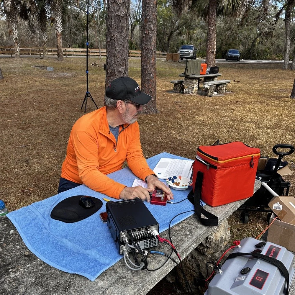
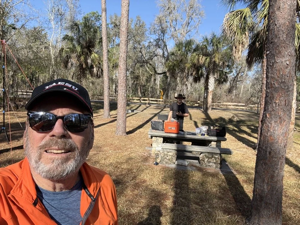
Chas operating his Yaesu rig from the adjacent picnic table. His vertical antenna is behind me and to my right. My wire antenna is behind him.
My operating position in the foreground with Chas visible about 30 feet away in the background—close enough for a park-to-park contact but creating some RF interference challenges.
20-Meter Band Issues: IRF520 vs IRF510 Amplifier Problems and Receiver Front End Overload"
The final two photos show a couple issues I've been wrestling with on my sBitx. The first image shows my sBitx operating on 10 meters with lots of noise lines visible in the waterfall display. These noise lines are coming from Chas transmitting Morse code on a different band, his signal is getting into my receiver and creating visible interference. I don't remember exactly what band he was on, but the important lesson here is that antenna placement matters tremendously when you're running multi-station setups like this one.
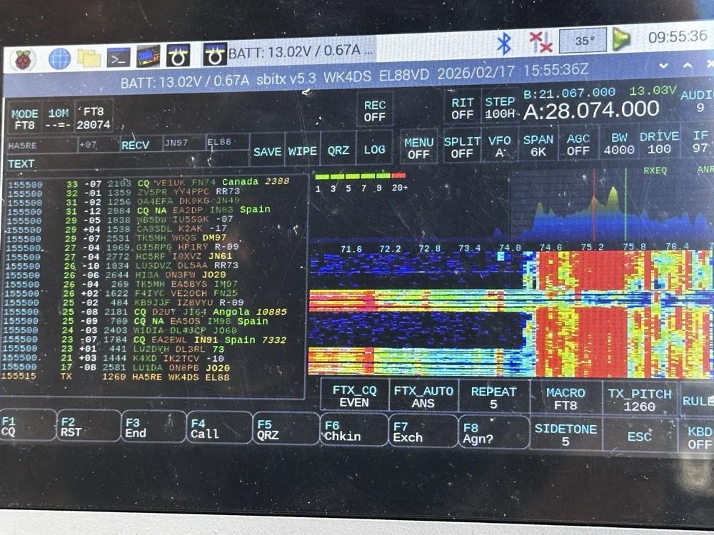
sBitx running FT8 on 10 meters (28.074 MHz) showing the noise spikes from Chas transmitting on a different band nearby 9in the waterfall) this is what front-end overload looks like in a multi-op field setup. The vertical lines in the waterfall are RF bleed-through from his station 30 feet away.
Be mindful of where you place antennas if you're operating a multi-operator event. We were only 30 feet apart, which is far too close for optimal isolation. I was still able to work many contacts even with this persistent noise coming through, though. This is something you learn to work around if you're going to be an amateur radio operator in a multi-operator event of any kind…think Field Day here. It's just part of the game, so you expect it and adapt. We could have used bandpass filters to eliminate most of this interference, but I didn't bring mine to the park.
The next photo shows my sBitx on 20 meters, and on 20 meters my radio has a persistent issue that I'm still troubleshooting. I'm beginning to believe it has to do with the IRF520 MOSFET transistors that I used in the power amplifier section when I built this radio. These IRF520 transistors have significantly more internal capacitance than the IRF510 transistors that Farhan originally specified in the revised amplifier design. I think this extra capacitance is causing the amplifier to oscillate, and that oscillation is what you're seeing as the noise signal in the photo.

sBitx on 20 meters CW mode (14.061 MHz) showing the noise from what I am suspecting is from oscillating mosfets.
Here's the interesting part: as the radio warms up during operation, this spurious noise signal moves down in frequency within the 20-meter band. If I want to push it out of the way temporarily, I'll switch to 40 meters or 80 meters and run FT8 for a few minutes. You generate more output power on those lower bands, which heats up the amplifier section faster. Usually, if I just run FT8 first thing when setting up, it warms up the transmitter enough to push the oscillation down to below where I normally work CW on 20 meters anyway, giving me a temporary workaround.
This isn't a permanent solution, obviously. I'm convinced I'm going to have to address this capacitance issue when I get back home, probably by swapping out the IRF520s for the specified IRF510s or adding additional filtering to the amplifier circuit. But for now, knowing the workaround lets me keep the sBitx operational in the field for POTA activations, which is what matters most.
Multi-Operator Challenges: RF Interference and Antenna Placement
Operating two stations in close proximity taught us several valuable lessons about multi-operator setups. The biggest challenge was RF interference between our stations. With antennas only 30 feet apart, we experienced significant front-end overload, when Chas was transmitting on his station, I could see his signal bleeding through into my receiver on completely different bands.
The sBitx has a somewhat easy-to-overload front end compared to more expensive commercial receivers, which made this problem more pronounced. But even with a better radio, operating this close together without bandpass filters or careful band coordination is asking for trouble. The solution for future multi-op activations is simple: either space antennas much farther apart (100+ feet minimum if possible), or operate on bands that are far enough apart in frequency that filter roll-off provides natural isolation.
The position of your antennas matters just as much as the distance between them. If we'd oriented our antennas at right angles to each other instead of parallel, we might have achieved better isolation through pattern nulls. These are the kinds of things you learn by doing, and they apply equally to Field Day operations where you might have multiple stations running simultaneously.
Despite the interference challenges, we still made excellent contact numbers. Multi-operator POTA activations are worthwhile because you can cover more bands simultaneously, operate different modes at the same time, and keep the activation going continuously while one operator takes a break. Just be prepared to work around the RF challenges that come with the territory.
Who Should Activate This Park?
Hillsborough River State Park is an excellent choice for both first-time and experienced POTA activators. Here's why:
For beginners: The $4 entrance fee is minimal, facilities are excellent with clean restrooms and covered picnic areas, and the tree coverage makes wire antenna deployment easy. You don't need to hike to reach good operating locations…everything is accessible by car right off the main loop road.
For experienced activators: The park's location north of Tampa puts you in a good spot for both domestic and DX contacts. The tall pines support wire antennas at significant heights, and there's plenty of space to spread out if you're running a multi-operator activation.
Best practices for K-1488:
Arrive early morning (8-10 AM) or late afternoon (3-5 PM) to avoid midday heat and sun glare
Bring sunshade or canopy, there's limited natural shade at the picnic tables
Plan for 2-3 hours of operating to get a good contact count
Cell coverage is good for self-spotting on the POTA network
Spring and fall offer the best weather conditions
If you're in the Tampa Bay area and looking for an easy, productive POTA park with good facilities, Hillsborough River State Park should be on your list.
Activating Hillsborough River State Park proved to be a highly productive POTA outing. Between Chas and me, we logged well over 100 contacts using QRP power and simple wire antennas…proof that you don't need high power or expensive gear to have success in Parks on the Air. The 65-foot EFHW at 35 feet worked exceptionally well, the Penntek TR-35 remains one of my favorite field radios for CW, and the sBitx v3 continues to impress despite some remaining amplifier quirks on 20 meters.
Key lessons learned: antenna height matters more than output power, multi-operator setups require thoughtful antenna placement to avoid interference, and limiting transmit power to 10 watts keeps your batteries happy all day. If you're looking for a beginner-friendly POTA park in Florida with good tree support and easy access, Hillsborough River State Park (K-1488) is an excellent choice.
Have you activated K-1488 or other Florida state parks? Share your experiences in the comments below, I'd love to hear about your favorite POTA locations and antenna setups.
Want more POTA activation reports and technical amateur radio content? Check out my other WK4DS blog posts for detailed equipment reviews, antenna builds, and field operation tips.
Frequently Asked Questions About POTA Activations
What is Parks on the Air (POTA)?
Parks on the Air is an amateur radio operating activity where hams set up portable stations in state and national parks to make contacts. Activators (operators in parks) try to make at least 10 contacts to qualify the activation, while hunters (operators at home) try to contact as many parks as possible. It's similar to Field Day but focused on public parks and conservation areas. POTA encourages hams to get outdoors, test portable equipment, and promote amateur radio to park visitors. The program started in 2016 and has grown to include thousands of parks across the United States and internationally.
How do you activate Hillsborough River State Park for POTA?
To activate Hillsborough River State Park (K-1488), you need to set up your amateur radio station within the park boundaries and make at least 10 contacts. Pay the $4 entrance fee at the ranger station when you arrive, then find a suitable operating location with trees for antenna support. Most activators set up at picnic tables near the main loop. Operate from battery power or a generator, no AC mains allowed for POTA activations. Log your contacts using a smartphone app like HAMRS or POTA Logger, then upload your log to the POTA website within a few days. The park has excellent tree coverage for wire antennas and is open from 8 AM to sundown year-round.
What is an EFHW antenna and why use it for POTA?
An End-Fed Half-Wave (EFHW) antenna is a wire antenna that's fed at one end through a matching transformer (typically a 49:1 unun), making it incredibly easy to deploy in the field. For POTA activations, EFHWs are popular because they require no ground radials, work on multiple bands without a tuner if cut for harmonically-related bands, and can be thrown into trees using a throw line and weight. My 65-foot EFHW works on 40m, 20m, 15m, and 10m, covering the most productive POTA bands. Getting it 35 feet high significantly improved propagation compared to running the same antenna closer to the ground. A properly deployed EFHW antenna at height will often outperform a vertical antenna at ground level for DX contacts.
Can you run two stations at the same POTA activation?
Yes! Running multiple operators at the same park location is allowed and encouraged in POTA. Each operator logs their own contacts and submits their own activation log. Chas and I each operated our own stations about 30 feet apart, which let us cover different bands simultaneously and maximize the total contact count. However, you need to be mindful of RF interference between stations. With our antennas so close together, I experienced front-end overload on my sBitx when Chas was transmitting on nearby bands. Solutions include better antenna separation (100+ feet apart if possible), using bandpass filters on receivers, or coordinating to operate on widely separated bands like 40m and 10m simultaneously.
What's the best QRP radio for POTA activations?
For CW-only POTA activations, the Penntek TR-35 is exceptional. It's lightweight (under a pound), battery-efficient, has outstanding CW break-in, and is nearly indestructible, perfect for field operations. For multi-mode operation covering CW, SSB, and digital modes, the sBitx v3 offers incredible value and capability in a portable package, though the CW keying requires careful technique and practice. Other popular POTA QRP rigs include the Elecraft KX2/KX3 (premium price but premium performance and battery efficiency), QRP Labs QCX-mini (CW-only, ultra-portable and inexpensive), and the Xiegu G90 (good SSB performance, acceptable CW, built-in tuner). Choose based on your preferred modes, budget, and how much weight you want to carry into the field.
How many contacts should you expect from a POTA activation?
Contact numbers vary widely based on propagation conditions, time of day, your operating skill, and whether you're spotted on the POTA network. A successful activation requires at least 10 contacts to count, but most activations yield 20-40 QSOs in an hour or two of operating. Our 100+ contacts in one afternoon between two operators was excellent, partly because we covered multiple bands and modes (CW, FT8) and had good propagation to Europe on the higher bands. If you're new to POTA, expect 15-30 contacts on your first few activations. Using CW typically yields more contacts than SSB due to pile-ups from hunters chasing parks, and FT8 can be productive when propagation is marginal or when SSB isn't getting through.
My 66 contacts plus Chas's 52 gave us 118 total QSOs from K-1488 on February 17, 2026. Ten of mine reached six countries across two continents, all at 10 watts or less.
You can help support this channel by using these Amazon Affiliate Links as well:
QRP/Portable Radios:
Antennas & Tuning:
CW Equipment:
Power & Accessories:
Organization & Transport:
BONUS ITEMS
73
David / WK4DS
Overall, today we had a wonderful day and made many contacts and was able to test antennas and enjoy ourselves in the warm Florida sun far from home where all the cold weather and dreariness is at. So until next time, get your radio out and go power it up and make a contact on it. That’s why you bought it after all.
Chas grabbing a photo from his perspective for posterity! HaHa! Look at all that stuff I brought!
Chito Branch Reserve: First FT4 Contacts, Meeting a Fellow Park Hunter, and the Quest for 1000
Doug's been activating Chito Branch quite a bit lately, and if I'm being honest, we seem to be in a friendly race to see who hits 1000 contacts from this park first. Spoiler alert: he's winning. But it was great to finally shake hands with someone who understands the appeal of spending beautiful Florida mornings in a park with Spanish moss hanging from the trees, headphones on, working the world.
February 10, 2026 • US-5524
Sometimes the best part of a POTA activation isn't the DX you work or the pile-ups you run! it's meeting another operator face-to-face who's been chasing the same goals you have. Today at Chito Branch Reserve, I finally got to meet Doug, KQ4SXW, in person.
I finally got to meet Doug, KQ4SXW
Doug's been activating Chito Branch quite a bit lately, and if I'm being honest, we seem to be in a friendly race to see who hits 1000 contacts from this park first (well, between us at least). Spoiler alert: he's winning. But it was great to finally shake hands with someone who understands the appeal of spending beautiful Florida mornings in a park with Spanish moss hanging from the trees, headphones on, working the world.
The Setup
I rolled into Chito Branch mid-morning with my usual portable arsenal. The park is close to where I'm staying in Tampa, which makes it an easy choice for activations, and I've been systematically building toward that 1000-contact milestone. As of today, I'm sitting at 769 QSOs logged from US-5524, so I'm getting close.
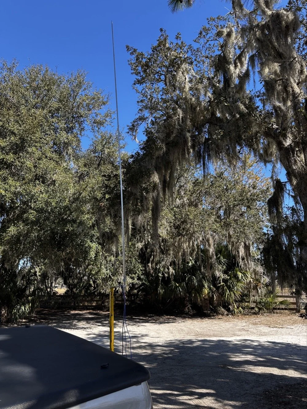
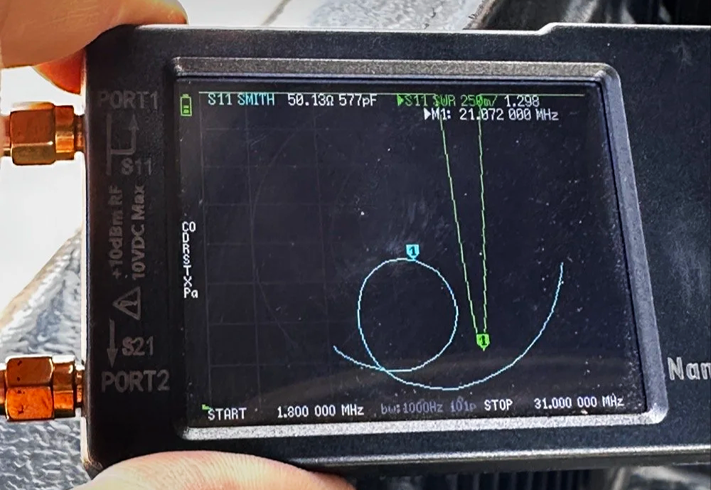
For antennas, I ran my 1/4-wave vertical with two counterpoise wires, tuned for each band. Simple, effective, and quick to deploy. I use the nanoVNA to utne the antenna with. As you can see in the plot above, I get it to something less than 1.5:1 SWR and call it good, I have found that if I get it to that level that I dont have any trouble making contacts at all. I have done OK with the SWR higher in the past…much higher actually, but it is a lot tougher to make contacts like that.
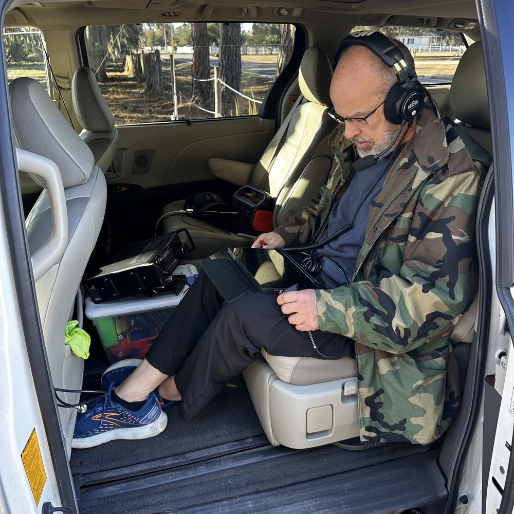
The main rig was the sBitx V3 from HF Signals for digital modes, and I brought along the Ten-Tec Scout 555 for some 15-meter CW work since the bands were looking promising.
Speaking of which… let me tell you about my grid square insurance policy.
A Sticky-Note Solution to a Real Problem
If you operate FT8 or FT4, you know that your grid square locator needs to be correct. It matters for awards, for logging accuracy, and frankly, for not looking like you don't know what you're doing. Recently, I completed an entire activation with the wrong grid square set in the software.
Not ideal.
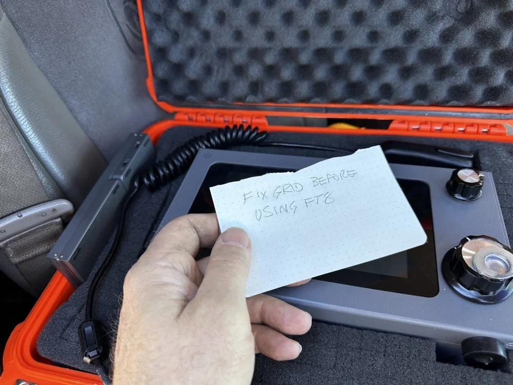
Sometimes the best solutions require the simplest answers…
So I came up with a foolproof solution: I now keep a note in my radio case that says "FIX GRID BEFORE USING FT8." It sits right on top of the sBitx when I open the case, impossible to miss. I also store the Bluetooth keyboard in the case with the radio so I can easily update the grid square in the field without fumbling around with the tiny on-screen controls.
Is it a high-tech solution? No. Does it work? Absolutely. Sometimes the best fixes are the simplest ones.
Starting with FT8 on 20 Meters
After getting the sBitx fired up…with the correct grid square, thank you very much… I started the activation with FT8 on 20 meters. I spotted myself on POTA and the responses started rolling in. There's something satisfying about watching those waterfalls fill up with decodes and seeing callsigns appear in the queue.
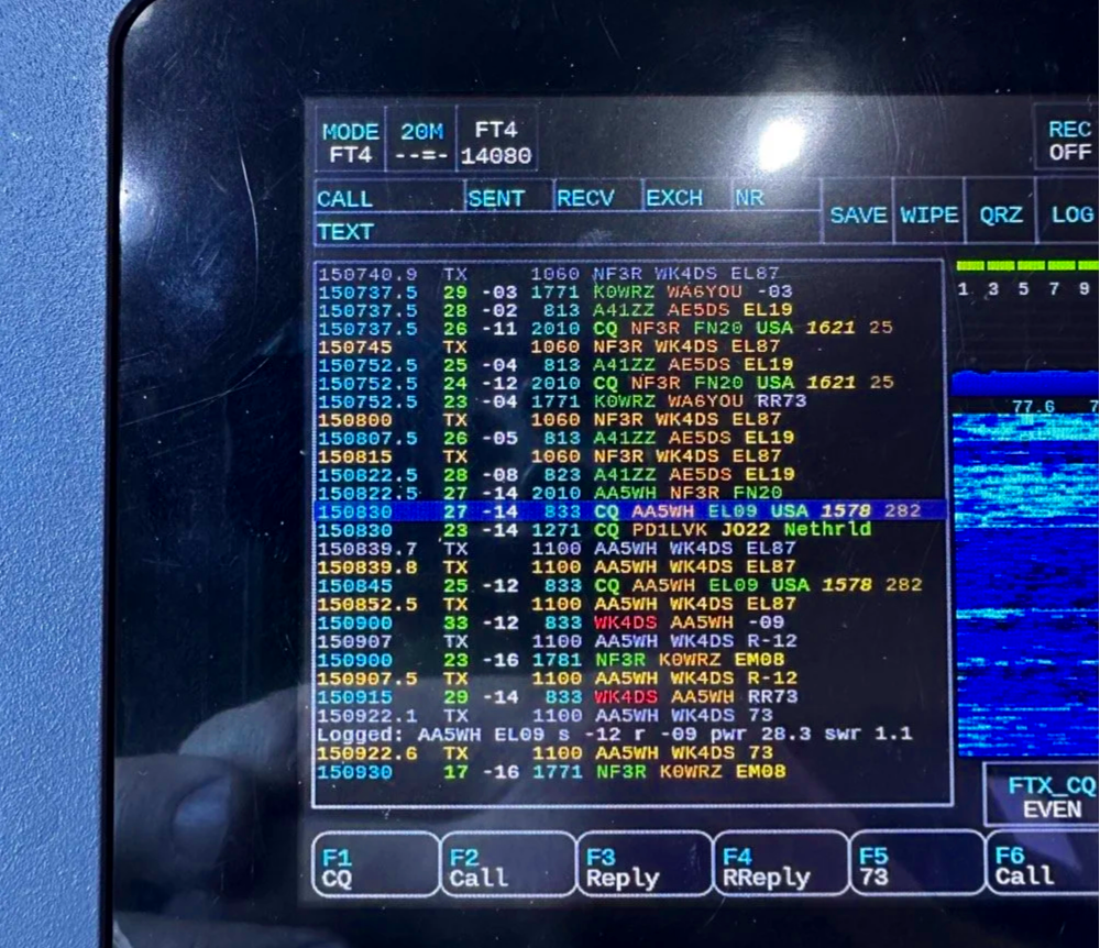
My very 1st FT4 QSO with the sBitx!
I worked through a solid session and logged about 18 contacts on 20-meter FT8. The band was cooperative, signals were good, and the activation was off to a strong start. Something to note about my sBitx V3 is that it has developed a sort of internal noise on 20 meters that lingers in the CW portion of the band. It goes down in frequency as the radio warms up so I have to figure out what is causing this problem when I get home the next time. I have it on the list right next to fixing my microphone pre-amp circuit for proper operation as well.
First FT4 Contacts at a POTA Park
After the FT8 run, I decided to try something new: FT4. I've run plenty of FT8 from parks, but FT4 was uncharted territory for me in the field.
FT4 is faster than FT8, cycling every 7.5 seconds instead of 15, which makes it great for contesting or when you just want to move quickly through a pile-up. I updated my spot on POTA again and started calling CQ. To be honest, I had used it a little in the shack before with no luck so I didn’t hold my breath today, To me utter surprise, I saw a QSO forming in the call feed on the left! Then it finished and logged it! I hurriedly got out my phone and snapped a quick photo to share with you guys…
First contact: AA5WH on 20 meters. Clean decode, solid signal, contact in the log. Then I switched to 15 meters and worked N1KLF. Two FT4 contacts, my first ever from a park, and honestly? I was pretty stoked. There's something satisfying about trying a new mode and having it just work.
15 Meters CW Was Alive
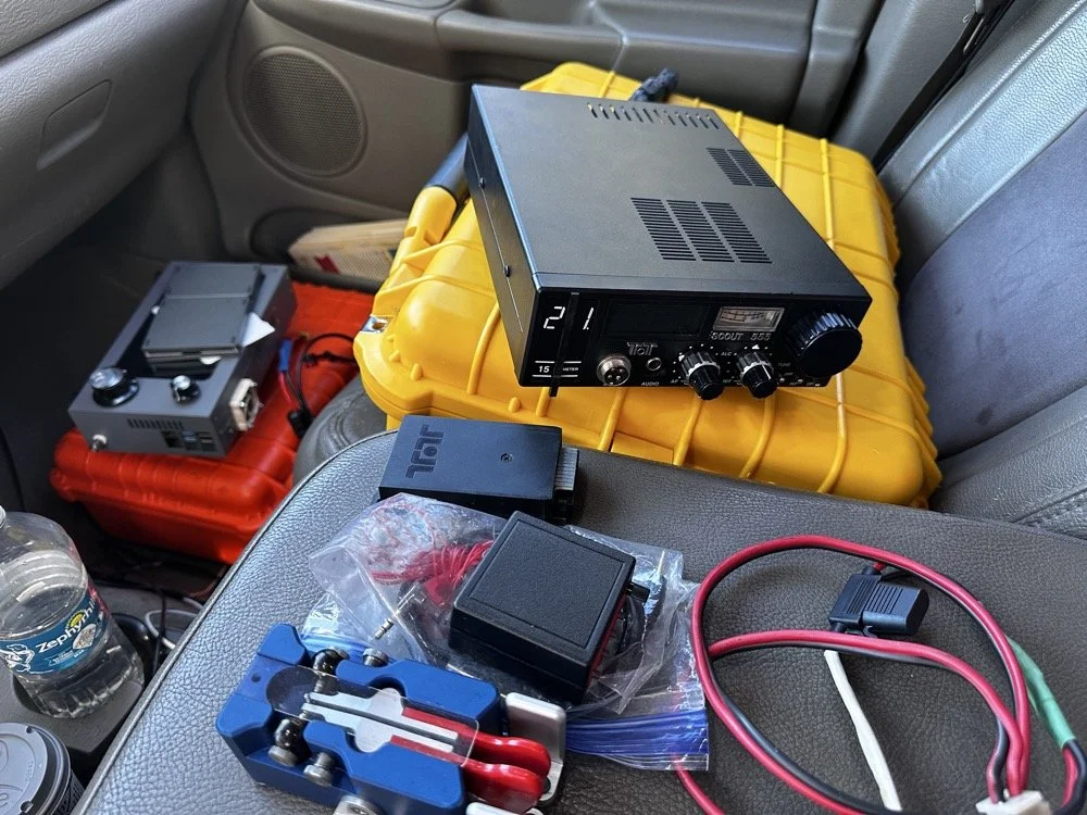
The TenTec Scout 55 is pictured with the HF Signals sBitx V3 where I was changing over to CW after working 2 digital modes today.
After the FT4 session, I switched gears completely. I packed up the sBitx and pulled out the Ten-Tec Scout 555 for some CW on 15 meters. The band was in great shape, though there was a bit of QSB rolling through. I got the radio all connected up to the keyer and then plugged in the Travler. My Begali Traveler key has become one of my favorites—smooth action, compact enough for portable ops, and it just feels good. It is sensitive, but that is how I use my keys, I prefer a light action myself and that is why I made my own paddles back in the day. N3ZN (Tony) and I2RTF(Pietro) make some of the nicest keys around at the moment and I am glad I have one from each.
DX Contacts That Made It Worthwhile
Right out of the gate, I snagged some DX that made the whole activation worthwhile:
EA4MZ in Spain
DD1LD in Germany
YV1GIY in Venezuela
PY5XT in Brazil
Four different countries, all on 15-meter CW with 40 watts and a telescoping 1/4 wave vertical, what more can you ask for? Days like this remind me why I love this hobby. Some of them were a little on the weak side but the Jones filter in the Scout actually helps if you open it up instead of closing it down. This seems counter intuitive, but opening the filter up just ever so slightly will let a lot more of the other operators signal though and just a little of the background noise, it is almost like having them turn their power up 50% or something, if you have not tried it with your Scout 555, I suggest you find a signal you can barely hear and give it a shot.
43 QSOs and Counting
By the time I packed up, I had 44 contacts in the log, though one turned out to be a duplicate, so 43 that counted. Not a huge number, but solid for a few hours of casual operating across three modes (FT8, FT4, and CW) and two bands.
Meeting Doug in person was the cherry on top. It's always good to connect with like-minded people in the hobby, especially when you're both chasing the same quirky goals. A thousand contacts from one park? Yeah, it's a bit obsessive. But things like that are what makes it fun.
SIDE QUEST TIME:
I ran into a unique problem today that is worth mentioning here. I was charging my computer with an inverter that I have wired into the cab of my truck. I was also running the truck so I could power the inverter and charge the computer as well as the sBitx V3 at the time. Well it turn out that I have some issues with this inverter that need resolving. The next few photos show the RF hash that this inverter is producing when under load! It is unreal how bad it was, I couldn’t believe all I had to do was simply shut off the engine and unplug the power cord from the logging computer and it went completely away…
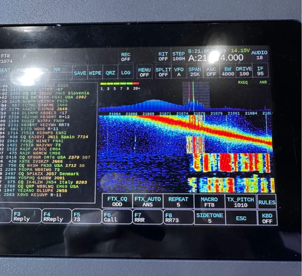
The above photo shows the hash of running both devices on the inverter with the engine running on the truck.
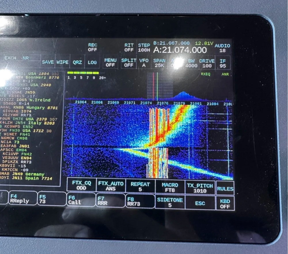
The next photo shows what happened when I shut off the truck and unplugged the computer.
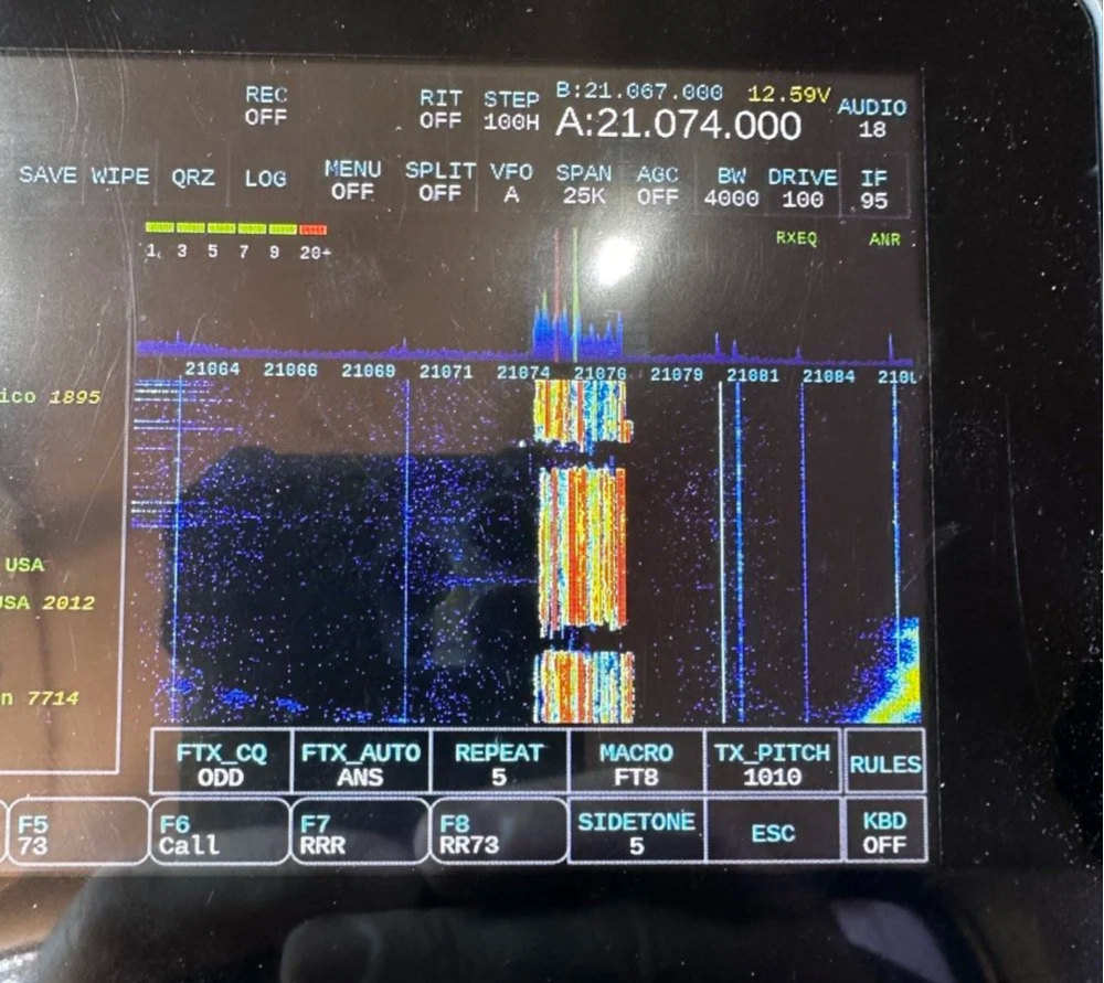
The last photo shows what the band looked like once I went around to the other side of the truck and powered off the inverter completely. This goes to show that you need to check these things if you plan to use RF devices like radios in the presence of RF trash generating devices like this inverter… Better inverter coming up!
END SIDE QUEST
Hit me up!
231 contacts to go until I hit the big 1000 from Chito Branch. At this rate, it'll take a few more activations, but I'm not in a hurry. Well, maybe a little… Doug's still ahead of me.
If you're in the Tampa area and see someone set up at Chito Branch Reserve with a vertical antenna and a tablet running digital modes, stop by and say hello. Chances are it's either me or Doug, and either way, you'll be in good company.
**Gear Used This Activation:**
- **Radios:** HF Signals sBitx V3, Ten-Tec Scout 555
- **Antenna:** 1/4-wave vertical with dual counterpoise wires
- **Key:** Begali Traveler
- **Digital Mode Software:** JJ and the sBitx 64 bit Development team version 5.301 (FT8/FT4)
- **Computer:** Dell Inspiron with Linux and HAMRS
- **Accessories:** NanoVNA for antenna tuning
Have you tried FT4 for POTA activations? What's your go-to mode for portable operations? Drop a comment below or find me on Facebook or shoot me an email on here.
What is FT4 and how is it different from FT8? FT4 is a digital mode similar to FT8 but with a faster cycle time (7.5 seconds vs 15 seconds), making it better suited for contests and quick pile-ups.
What equipment do I need for POTA FT4 activations? You need an HF transceiver capable of digital modes, a computer or tablet running WSJT-X software, an interface between your radio and computer, and a suitable antenna for your chosen bands.
Where is Chito Branch Reserve located? Chito Branch Reserve (US-5524) is located in the Tampa Bay area of Florida and is part of the Southwest Florida Water Management District.
How many contacts do you need for a valid POTA activation? You need a minimum of 10 QSOs to qualify for a valid POTA activation.
You can help support this website by using these Amazon Affiliate Links:
QRP/Portable Radios:
Antennas & Tuning:
CW Equipment:
Power & Accessories:
Organization & Transport:
BONUS ITEMS
73,
David WK4DS
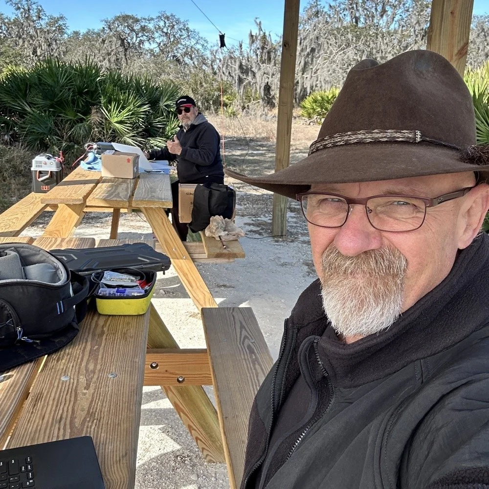
Joint POTA Activation with NA2B at Moody Branch: 104 CW Contacts in 4 Hours
Today I went to a POTA park to meet up with Chas NA2B, another amateur radio operator that lives just down the road from Chito Branch nature Reserve where I have been spending a lot of time here lately. He saw I was at the park on the spot page and simply hopped in the car and drove over for an eyeball QSO and to see if I wanted to meet up with him at some point and setup for an activation.
Today I had the pleasure of meeting Chas NA2B for our first joint POTA activation at Moody Branch Wildlife Management Area (US-6317) in Florida. What started as a chance encounter on the POTA spot page turned into a memorable 4-hour operating session that netted 104 total CW contacts between our two stations.
Today I went to a POTA park to meet up with Chas NA2B, another amateur radio operator that lives just down the road from Chito Branch nature Reserve where I have been spending a lot of time here lately. He saw I was at the park on the spot page and simply hopped in the car and drove over for an eyeball QSO and to see if I wanted to meet up with him at some point and setup for an activation.
This blog post will be an amalgamation of both discussing the activation as well as my new friend.
Planning the Activation
We communicated a good bit over the past week via text to line up a good day, (turns out every day is a good day for Chas…haha) and chose Tuesday as I had some business to attend to on Wednesday and the weather was way warmer than the previous day. The weather actually turned out to be about perfect to be honest about it. We agreed on Moody Branch US-6317 and 9:30 as the start time. We had planned to operate till about 2 if things were going good so on the day of, I load up the truck and head out. It takes about an hour to get there from where i was staying so I stopped and grabbed coffee and snacks along the way. Who doesn’t want a caffeinated CW op on the other end of their QSO???
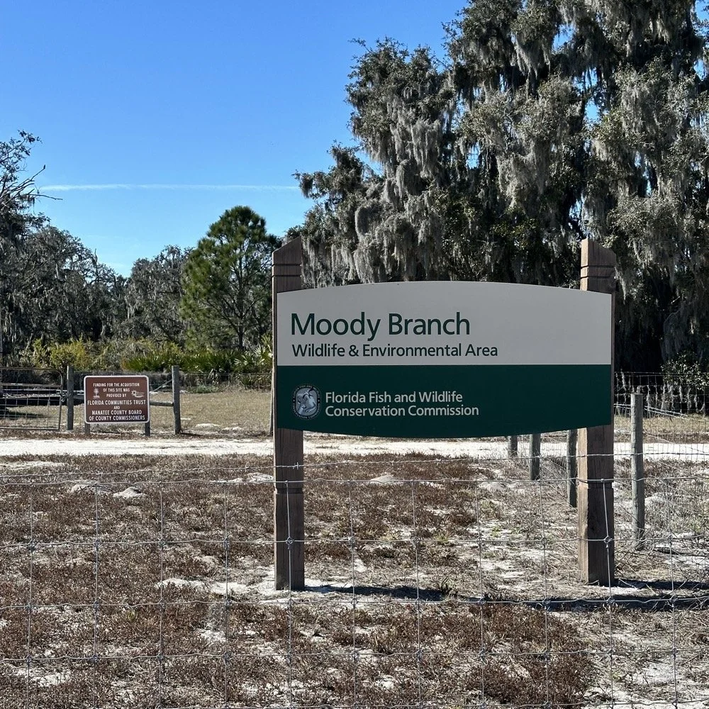
When I get there I am greeted with the standard issue Florida DNR signage and to my amazement there is a pavilion for us to operate from! Now to be fair, Chas had told me about it and the proximity to the parking lot. You see it was literally 15 feet from my truck to the table. Having the table this close allowed for an incredible amount of gear to be brought out. HaHa
Chas had already arrived and was setting up in the back of the pavilion so that I could have the closer spot and access to some really good trees to hang my antenna in. I decided to setup the antenna “properly” by putting the antenna tuner at the antenna instead of at the radio. This should provide better radiation than using the tuner to match the feedline as part of the antenna system. I simply set the case on the ground and set the tuner on top of it and tied the antenna wire to the case itself. The distance was about 50 feet from the table so I had to couple both of my longest coax cables together just to reach the tuner out by the tree.
The Setup: Remote Antenna Tuner Configuration
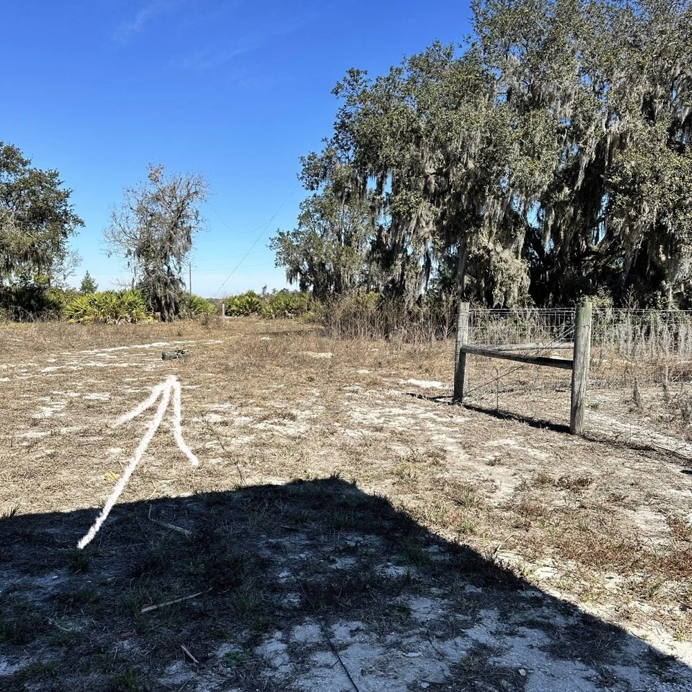
I put the antenna tuner way out here on purpose. The remote tuner setup keeps the feedline from becoming part of the radiator. This is important at it creates a more efficient antenna overall.
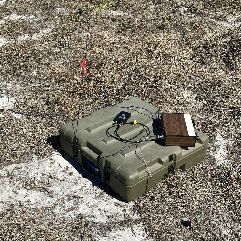
Since it was so far from the table, I just left the nanoVNA with the tuner so it would be nearby when I wanted to make band changes, of which there was many!
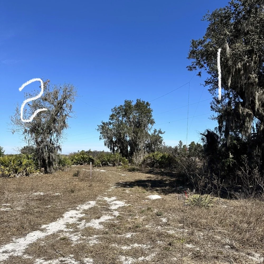
I strung the wire up like an inverted L type from tree 1 to tree 2 and tuned it for 40 meters to start with. Today I chose to start there as I was wanting to make contacts on all the bands I could with the Penntek TR-35 QRP radio. I also decided at the outset that I would work bands other than 20 meters today to see what I could come up with. I usually seem to have great luck with all the bands…other than 60 meters so far… haha. I also chose to run 10 watts or less all day too…well except for 40 meters, I ran 40 watts on 40 meters and still only made one FT8 contact there… lol. The band was just too noisy for me to hear anyone.
Equipment: QRP vs. Comfort
I only ran 10 watts or less the rest of the day because I didn’t have my large battery with me that I bring to power the sBitx at full power. I only had my 8 Ah battery and I didn’t want to deplete it early. I also had the 3Ah battery for the TR-35 and used it with that radio, but those were the power sources I was constrained to. This made me have to work a little harder for contacts, but it also made it a lot more fun to get DX stations in the log! I got at least 2 European stations in the log so I know it doesn’t take a ton of power to do it.
WK4DS (left) and NA2B (right) running simultaneous CW pileups on different bands at Moody Branch
Once setup I used two radios, the Penntek TR-35 QRP rig and the HF Signals sBitx V3. Both of these radios are cool in their own respect. I like the sBitx because I can run FT8 without needing to also connect a computer to the radio. The sBitx will internally log the contacts too so I could theoretically do an activation then when I get back home, down load the contact list and reformat it in ADIF and send it to the POTA site. That is kinda cool. The Penntek TR-35 is small, light weight and has a great receiver in it as well as awesome filtering. This little radio has everything you need and nothing you dont.
Above is me and Chas running pile ups on two different bands at once! We were both running CW today and at times I struggled to hear as my side tone and his were the same. I solved this by adjusting the side tone up a little so then mine and his were different ever so slightly and I could hear mine easily again. I think Chas stayed on 20 meters the whole time today. He racked up 61 contacts with the simple wire antenna. What a day in the field!
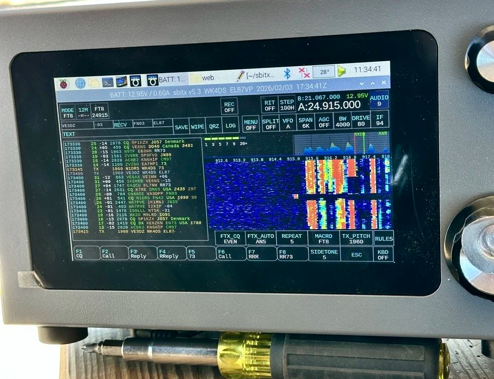
sBitx V3 running FT8 with new color-coded software from the open-source development team
This is what you see with the latest software release from the open source team on Github. This software has been made VERY good by this team of dedicated people and if you want to use this software yourself, just follow this link to JJ’s github page to learn more.
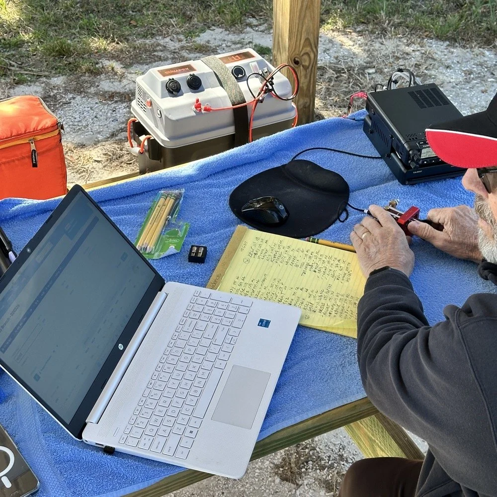
NA2B's minimalist CW station: paper logging, pencils, and a clean operating position
Chas had a really clean operating position today. He had plain pencils, which will ALWAYS work, a pencil sharpener and notebook for log data. He was in a blissful state. I also like the battery pack he has too. If I had brought my 36 Ah battery, I would have brought the Scout 555 out and ran it as well. Maybe forgetting it was a sign that I needed to let that radio rest a little…haha. His station looks so clean though, I was impressed.
My station on the other hand looked like I set off a “ham-grenade” lol… I had the logging computer, the foldable keyboard for the sBitx and the whole Penntek station was just piled in the orange storage case. Along with all that, I also had all sorts of other stuff that isn’t in this photo scattered around the table… It was kinda crazy how much crap I brought out.
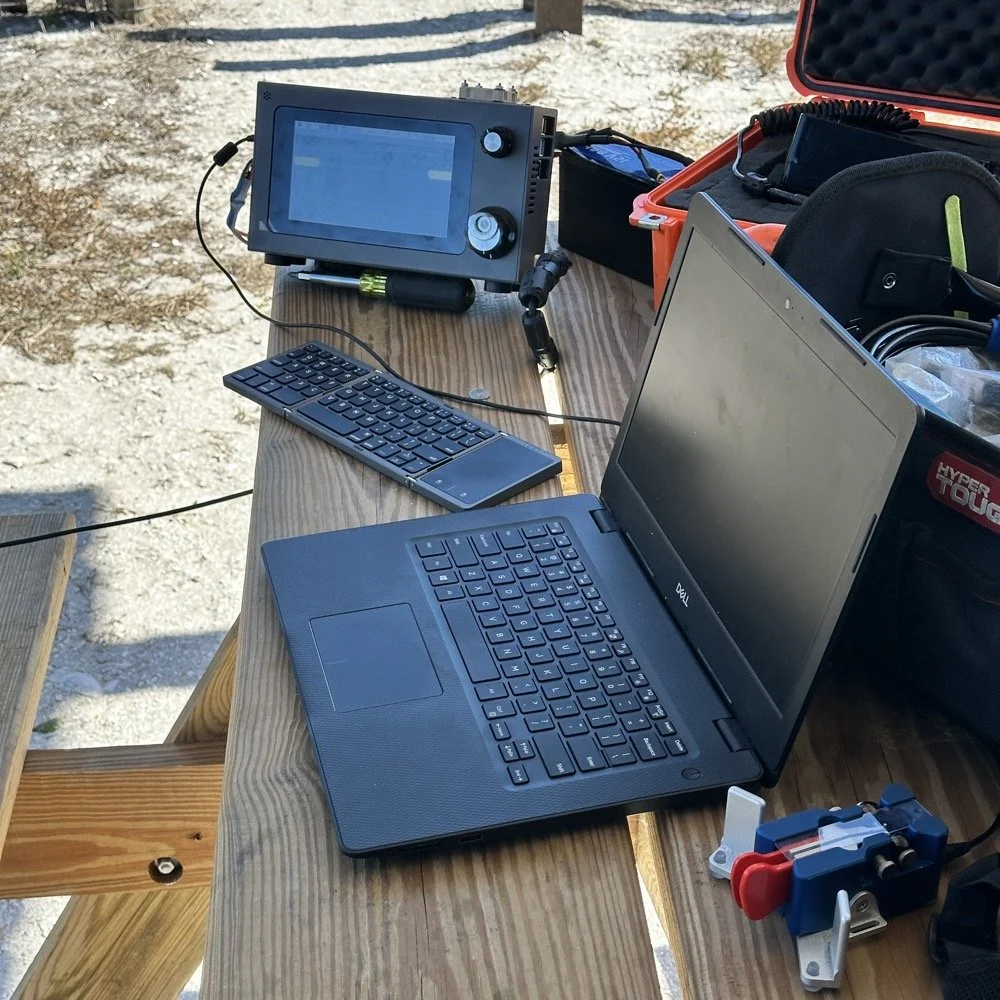
Operating Highlights
Chas setup his camera and grabbed this photo of us below for the blog. I like how his station has one box on the table and mine is covered in stuff! HAHA!
I will be honest, it was a lot of fun just hanging out while doing the activation. I do so many of these by myself that I forget that I can have someone with me while I do this.
We didn’t get in a hurry, we just took our time and whatever calls got in the log is what we got. There were a couple of time we both had decent pileups to work through, him more so than me as he had more power and 20 meters typically has more operators on the band. It wasn’t about QSO count…till it was… but all day we just made contacts and played radio.
Right before we finished for the day, I asked Chas how many contacts he had. Chas had 60 calls in the log and I had 38. I told him that we needed to have an even 100 calls between us before we stopped for the day. This total number of QSOs was completely arbitrary, but a cool little milestone none the less so we pushed on for a little longer. We finished the day with 104 total calls in the logs. Win! Chas had 61 as a final count and I ended up with 43! What a day!
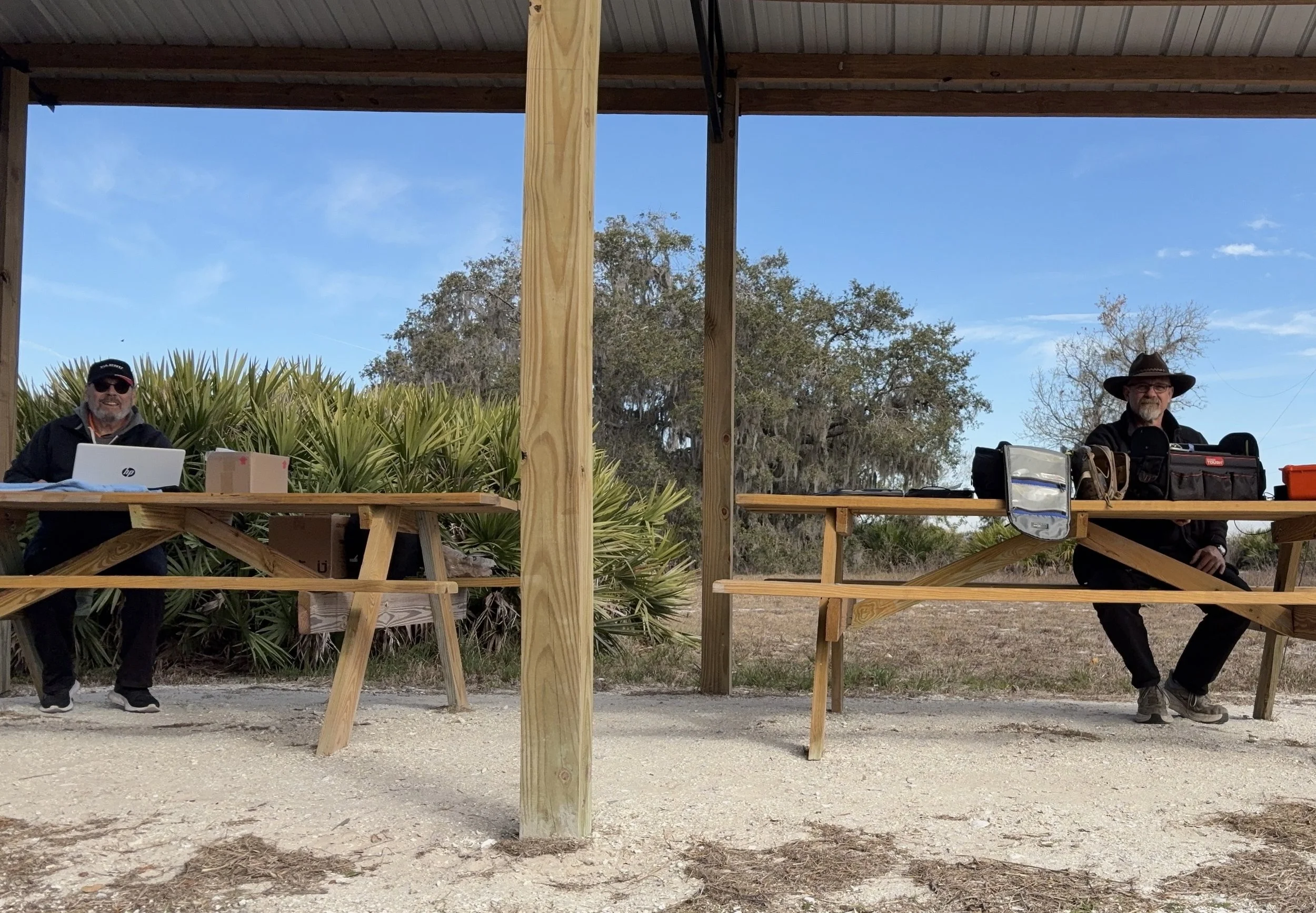
Multi-operator POTA setup at the pavilion - note the contrast in station complexity!
After about 4 or 5 hours of fun and games, we decided to break down and head back to our wives to get some lunch. It was a great day and I am glad I made a new friend as well.
Activation Summary:
- Park: Moody Branch WMA (US-6317)
- Operators: WK4DS & NA2B
- Total Contacts: 104 (43 WK4DS + 61 NA2B)
- Mode: Primarily CW, some FT8
- Bands: 40m, 30m, 20m, 17m, 15m
- Radios: Penntek TR-35 (QRP), HF Signals sBitx V3, Yeasu FT-891
- Power: 10 watts or less (QRP), 40w on 40m, 50 watts on 20m
- Antenna: Inverted L wire antenna with remote tuner, (Chas ran a random wire)
- Duration: 4-5 hours
You can help support this website by using these Amazon Affiliate Links:
QRP/Portable Radios:
Antennas & Tuning:
CW Equipment:
Power & Accessories:
Organization & Transport:
BONUS ITEMS
73
WK4DS - David
![Ten-Tec Scout 555 60m Band Module Build: Final Filter Tuning & Field Testing [Part 3]](https://images.squarespace-cdn.com/content/v1/5d17806ce65eba00011667cb/c2e621e7-9bb7-4b40-b20f-7c5c2dc8be7d/IMG_1257.JPEG)
Ten-Tec Scout 555 60m Band Module Build: Final Filter Tuning & Field Testing [Part 3]
Today I took the newly minted 60 meter band module for the Ten Tec Scout 555 out on it’s maiden voyage to a POTA activation. I made a contact in the shack with it before leaving on my short trip to Florida so I felt confident it was ready to use. Today we are discussing what happened and what is going on from there with the 60 meter band module project. (Spoiler Alert: It kinda wasn’t really ready yet…)
Today I took the newly minted 60 meter band module for the Ten Tec Scout 555 out on it’s maiden voyage to a POTA activation. I made a contact in the shack with it before leaving on my short trip to Florida so I felt confident it was ready to use. Today we are discussing what happened and what is going on from there with the 60 meter band module project. (Spoiler Alert: It kinda wasn’t really ready yet…)
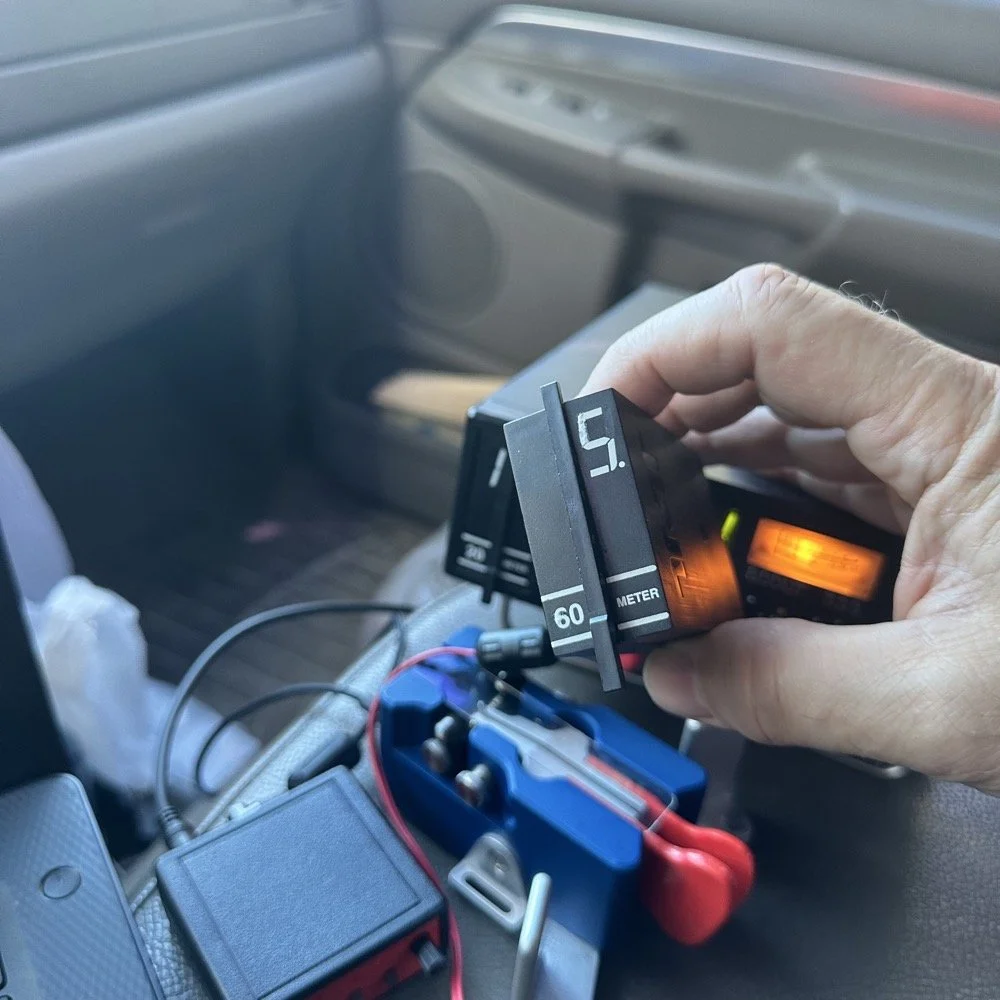
As you can see from the spot page report below, I was the only one on 60 meters this morning and it was roughly 9:45 (might have been 10 to be honest, I cant remember) local time before I got everything setup and running. This made 60 meters not a great choice to be honest for a daytime band. The 60 meter band is a great evening and really early morning band, but once the sun comes up these low bands tend to get really noisy. The band noise was quite low to my surprise today. I usually get a good bit of man made noise in this spot so I was pleasantly surprised when the noise floor was really low…or the band was closed. Who knows at this point?… I am starting to lean towards the band being closed as I couldn’t hear the FT8 crowd either, and those guys are ALWAYS on the band if it is open at all.
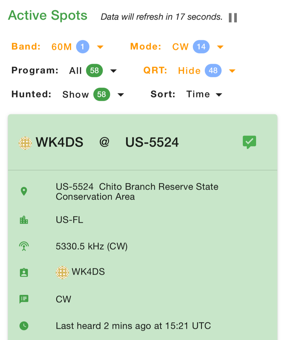
Undaunted by this and the lack of any kind of signal on the band, I setup and started calling CQ…and called …and called… then I finally got a station in North Carolina ( WA4CHJ - thanks for answering me, I really appreciate it. ) and with that I had a call in the log on 60 meters with a Ten Tec Scout 555!!! I can’t be certain this has been done by someone else, but as far as I know, I am the first to make that happen! After calling CQ for about 7 more minutes with no answers, I noticed that the ALC light was not coming on when I would key the radio and it was showing about 20 watts forward power on the built in meter. I checked the SWR and it was fine so it had to be in the module. I tried calling for a little longer and started getting an odd kind of “hashy” crackle on the CW sidetone and when it would make this sound the power would go up to the normal level and the ALC would come on…Upon this realization, I decided it would be better to sideline the module till I got back to the work bench next week instead of risk damage to the module or the rest of the radio. It also occurred to me that the RBN never heard me, not one time, while calling on this day so the band must have been closed…
You gotta admit though, that setup below is kinda sweet… Also the frequency is tuned off by the side tone (this is normal for the Scout 555) so it is actually on 5.3305 mhz in this photo. (I checked it with my Omni-VII before leaving home so I knew it was on frequency)
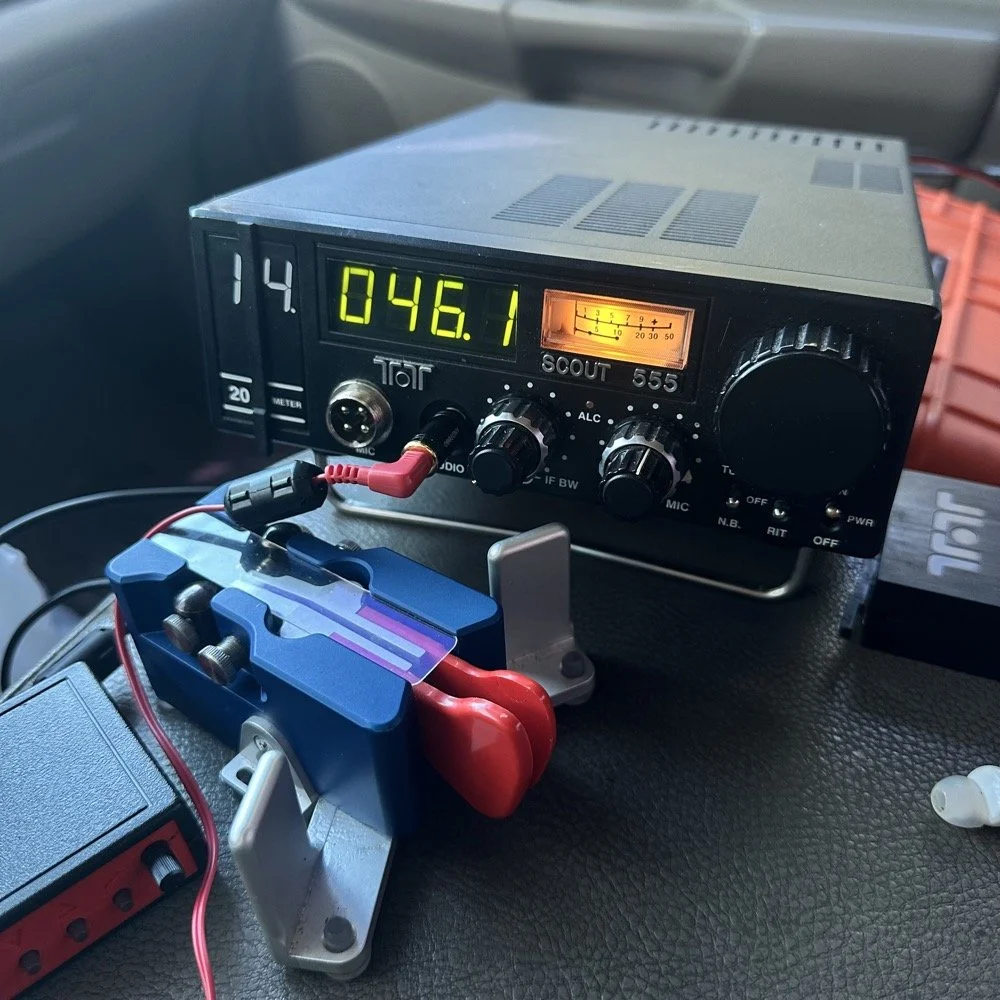
I setup a long wire today since my vertical will only tune to 40 meters with the home-brew load coil and I was a little strapped for time and just used an MFJ manual tuner instead. This allowed me to get a 65’ wire up in the air and a couple of radials and run with it. I was able to tune it well into the 60 meter band with the null covering the entirety of the band space so no tuner changes were needed as I moved around in the band.
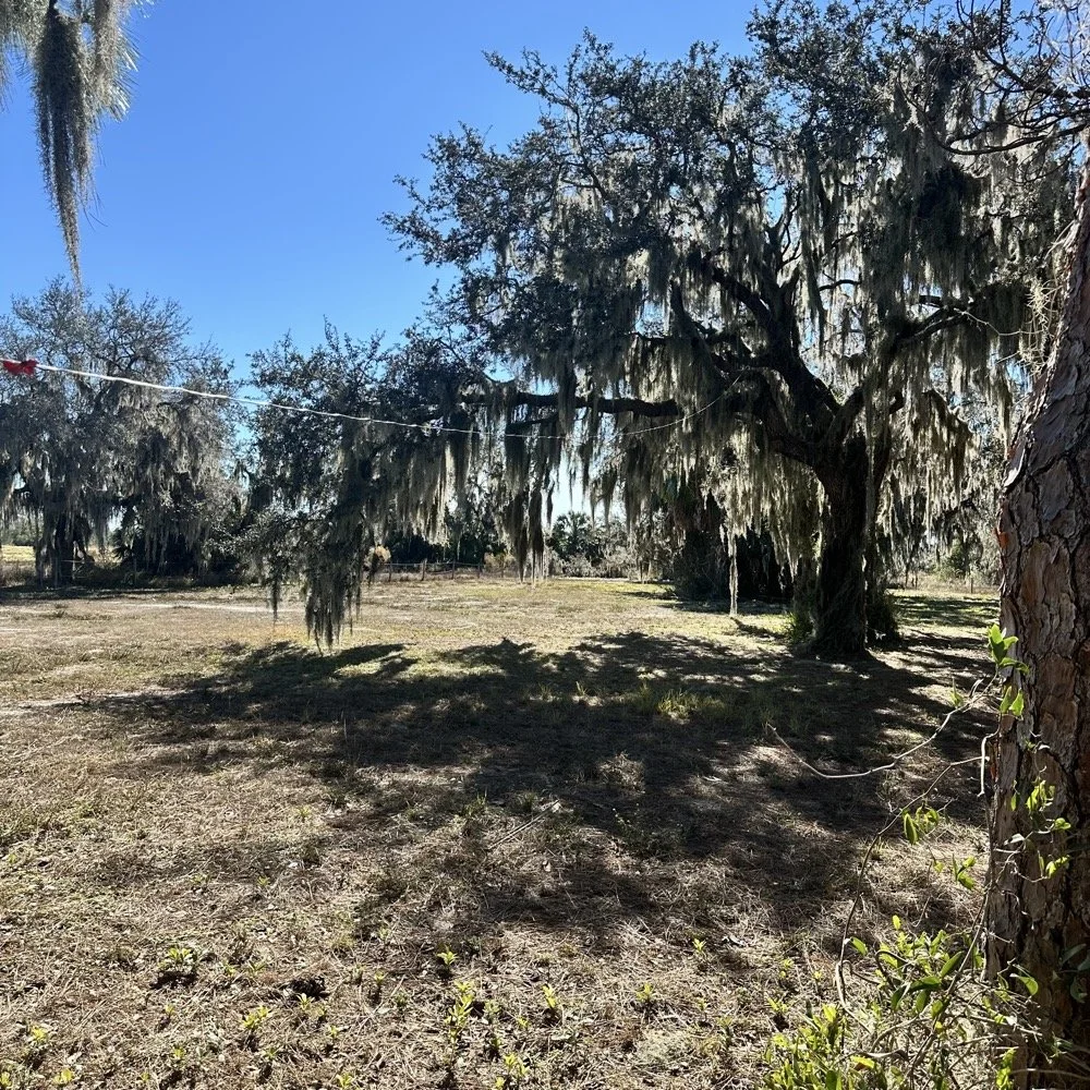
SIDE QUEST:
This little segment will be about the rest of the activation for my readers that follow those as well.
Today was a great day…once I moved to 20 meters! Turns out 20 meters was alive and well today with only about 6 CW activators on the band. This gave me plenty of room to find a nice quiet frequency as well as lots of hunters were out today as well. I tuned up on 14.047 mhz and started calling CQ, I think it took two calls max to call in a extraordinary pile up for me! The stations were deep and strong! I swept aside my normal pleasantries for the most part and compacted the closing to what I felt was a minimum and the calls just kept coming in! I worked 49 calls in 41 minutes! That is a record for me! At this point I literally called CQ one last time to make sure there was no one else waiting and got no replies so I immediately called QRT and shut down the radio. I was actually out of time and had to get the rig packed up since I needed to pick up the wife from class. This had to be the fastest 49 calls in the history of WK4DS amateur radio in my totality of radio… haha.
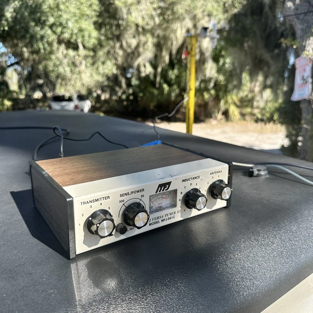
MFJ was a company that some complained about (Surely you have heard them called More Fine Junk) but to be honest, everything I have ever bought that they made has worked exactly as described and was pretty reasonable in price too. I hope someone fills these shoes for the future hams coming into the hobby, this little tuner is amazing for what is in that tiny little housing. It tuned this long wire just fine and didn’t need huge capacitors or inductors to do it. Not to mention it was really economical too. Good kit is hard to find so if you plan to do POTA in the field, I recommend one of these in the box of stuff, it WILL bail you out one day. This tuner has bailed me out a couple of times now…
A throw line, a weight (that I made in the machine shop out of scrap stainless steel) and 65’ of wire made for a lot of fun today.
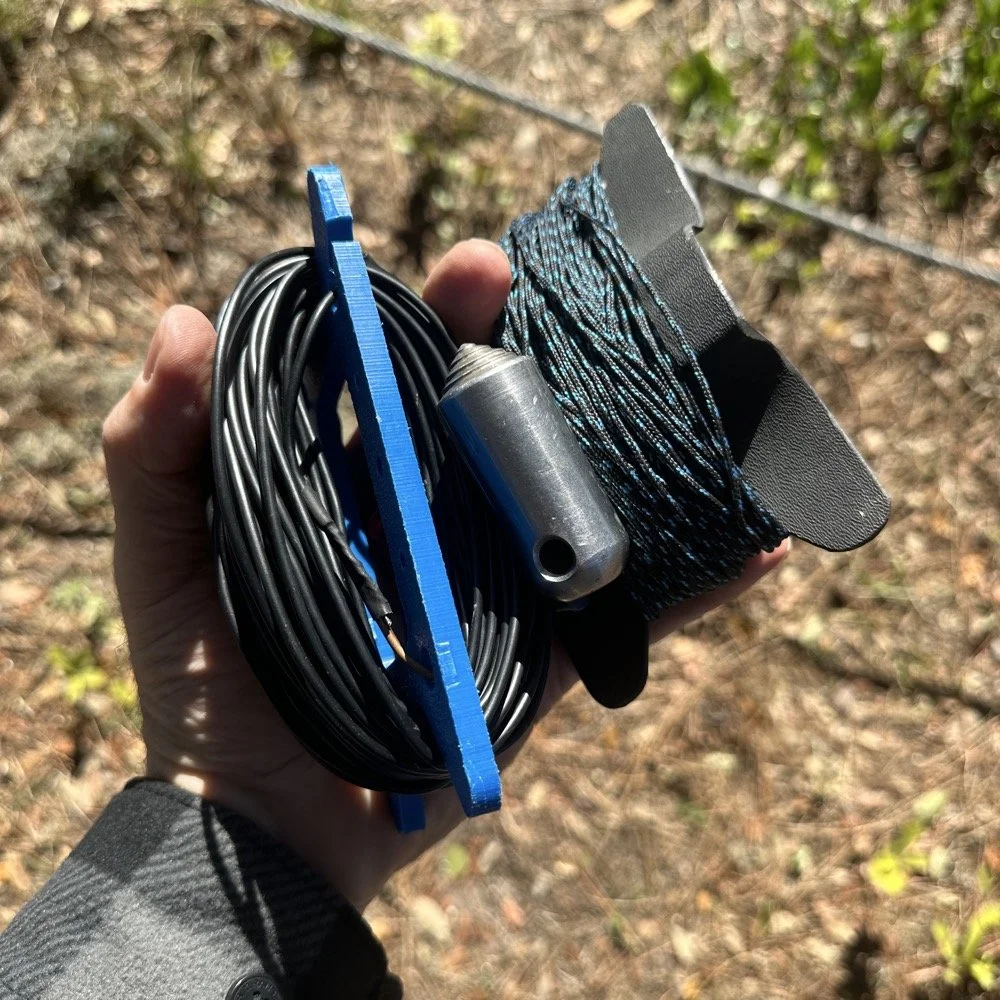
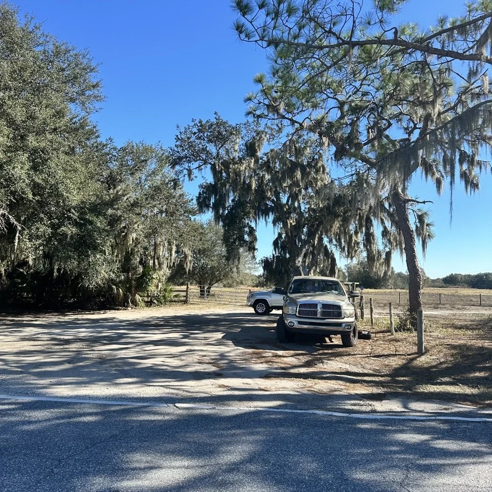
You can’t really tell it in the photos, but I did use my vertical antenna truck mount. I used it as the truck side anchor for the long wire and strung it up into the tree you saw earlier. This turned out to be really convenient I must say.
SIDE QUEST ENDED:
Back to the project at hand…
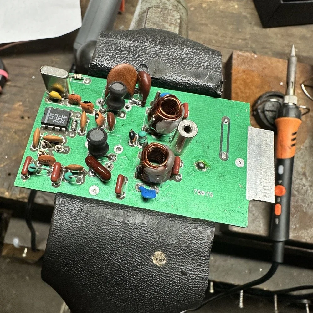
A week later and back in the shop at home with the band module on the work bench again and a Scout 555 in the shop now instead of the ARGO 556 to give me full power (40 watts) into the module (I pull the output power back to 40 watts to help protect the radio).
Now I can sort out the last of the details with the filters under full load. I am starting to think that the LO BP filter still needs some work as well as the signal level on the mixer output filter is REALLY high. I don’t remember the exact number but think of something like 700 or 800mV level instead of the 50mV that is supposed to be coming out. I tackle this problem first by building up the board like I had before so I could see the level coming out of the mixer filter. I had removed one of the impedance matching capacitors completely (750pf) without understanding what I had done and this was a big part of the problem with the level being so high. I did some simple math and came up with about 600pF instead of the 750pF that was supposed to be in the board since it was now tuned for 5.35 mhz instead of 3.55 mhz. I ended up using a 560pF cap and the level looked like the photo below on the base of Q16 in the radio. Remember this data is at this link if you need it as NA5N made these wonderful signal flow graphics.
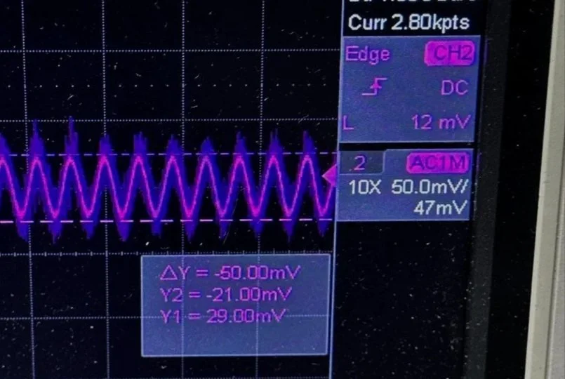
Right on the money at 50mv! I will take that everyday! All the noise you see on the signal is generated in the radio as far as I could tell, all the band modules I tried today looked like this on the base of Q16…or I was picking up the noise from somewhere else, I really am not sure to be honest with you. The output from the collector looked fine though so I don’t know what is happening here. I know this is good now as the frequency in the radio is stable and doesn’t drift. Those NPO capacitors paid off! (NPO means “Negative-Positive 0 ppm/°C” or more plainly, these capacitors are stabilized so they don’t drift in value with a change in temperature) My circuit doesn’t look exactly like the original Ten Tec filter but it does work.
Below is what I ended up with for the filter circuit. I added the one capacitor that was not in the original design (the 43pf cap) and this did seem to help with the shape of the filter so I left it. I drew my filter flow direction backwards from the Ten Tec drawing but you can see the differences from the 80m filter I started with below. Also a couple points of interest here. In my 60m module (formerly an 80 meter band module), the output from the mixer chip is pin 5 on my board and not pin 4 that feeds into the filter network. If you look at the spec sheet, this is fine as both pins are output pins, but it was a curious mistake in the schematic I found while troubleshooting my module. Another curiosity to me is that the schematic shows L6 in parallel with C8 (5pf) in the center of the filter. Not one single band module uses L6… at all. The chart underneath the schematic shows a -0- symbol on each one of the modules for L6, to confirm this, I looked in three different modules and none of them have this inductor in them. It isn’t present on the 10 or 12 meter modules either as they have a different layout for their filters. This was a provision that later was deleted I suppose. Kinda neat to find things like this while doing a project. Makes you wonder why they provisioned for the inductor but never used it. The board has two through holes for the inductor as this is where I placed my 15pf cap (which made adding it really convenient.) So it was obviously designed into the system to start with… Maybe someone who was an engineer at Ten Tec back then will comment.
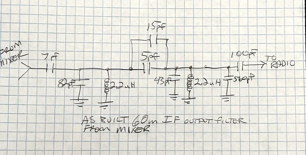
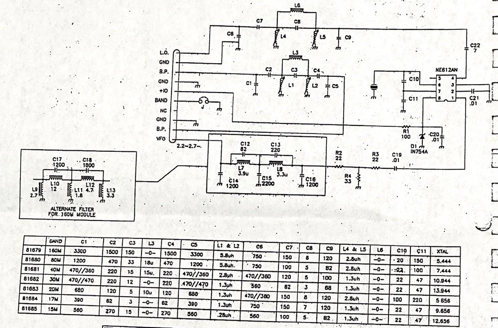
Excerpt from original Scout 555 owner’s manual.
With that out of the way I moved on to the output LP (Low Pass) filter that the 50 watt power amp flows through to get to the antenna.
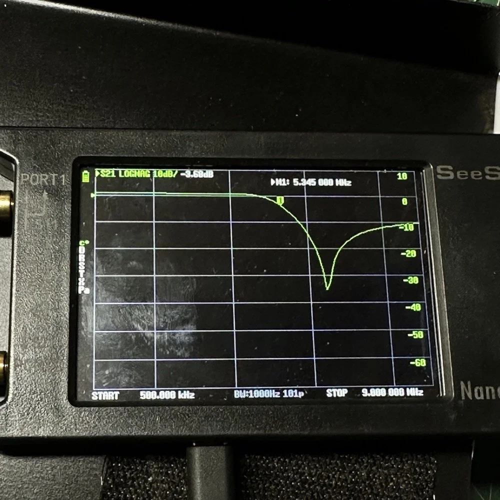
The above photo is of a LP filter out of an unmodified 80 meter band module I used for comparison. If you will notice the roll-off is right smack dab in the middle of the 60 meter band on this particular module.
The photo below is of the 60 meter band module sweep that I am building out of an old 80 meter band module. If you will notice I have the nanoVNA set to 5.430 mhz on the marker, and it is hard to see, but the signal is at 0.05dB which is basically zero losses at the highest band position possible. This would imply that the filter would allow the 60 meter band through just fine, but it would not…
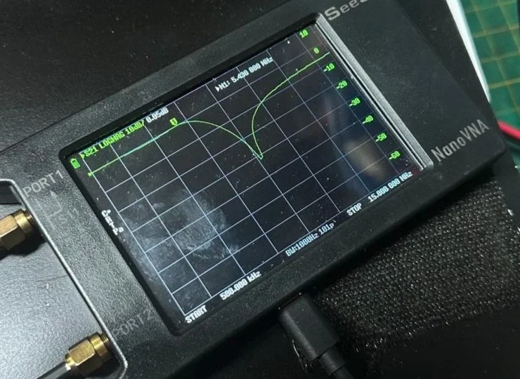
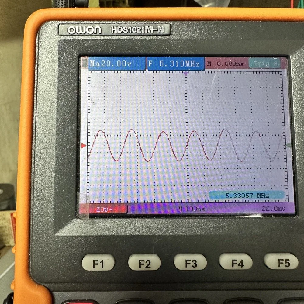
This is what the radio was sending to the dummy load after it passed through the LP filter module (above photo)… So to test this theory, I installed a different module (40 meters) and got what you see below… That is a little over 120 volts peak to peak on 40 meters. Yeah, you don’t change the output power of a Scout without a screw driver so the fact that the 60 meter band module I made is only letting a little over 30 volts peak to peak through it AND knowing that the 40 meter band module is passing over 120 volts peak to peak, tells me the 60 meter filter is choking off the energy and it is probably heating up the toroid inductors pretty good at the same time. I suspect that is what I was hearing the other day at the park when it was crackling after a while. I just hoped that I had not burned the wire on the inductors with this energy… If so I would have to rewind the inductors completely from scratch. Fortunately, I do have a roll of magnet wire I could do it with…
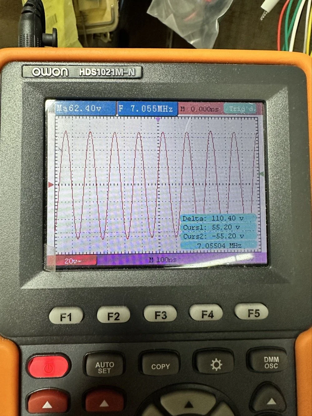
Into the final output LP filter I went (the one in the can) to see what I could do with it. The first photo shows the “can” the filter is shielded inside of to keep stray RF at bay.
The second photo shows what is inside of this can. This is also a photo of my completed filter with modifications to make it work on 60 meters. I found that this module had been tampered with once inside. Now to be fair, I did work on this module at one point to repair a broken inductor lead, but that was all. Now, I am getting much more serious while inside of the can…
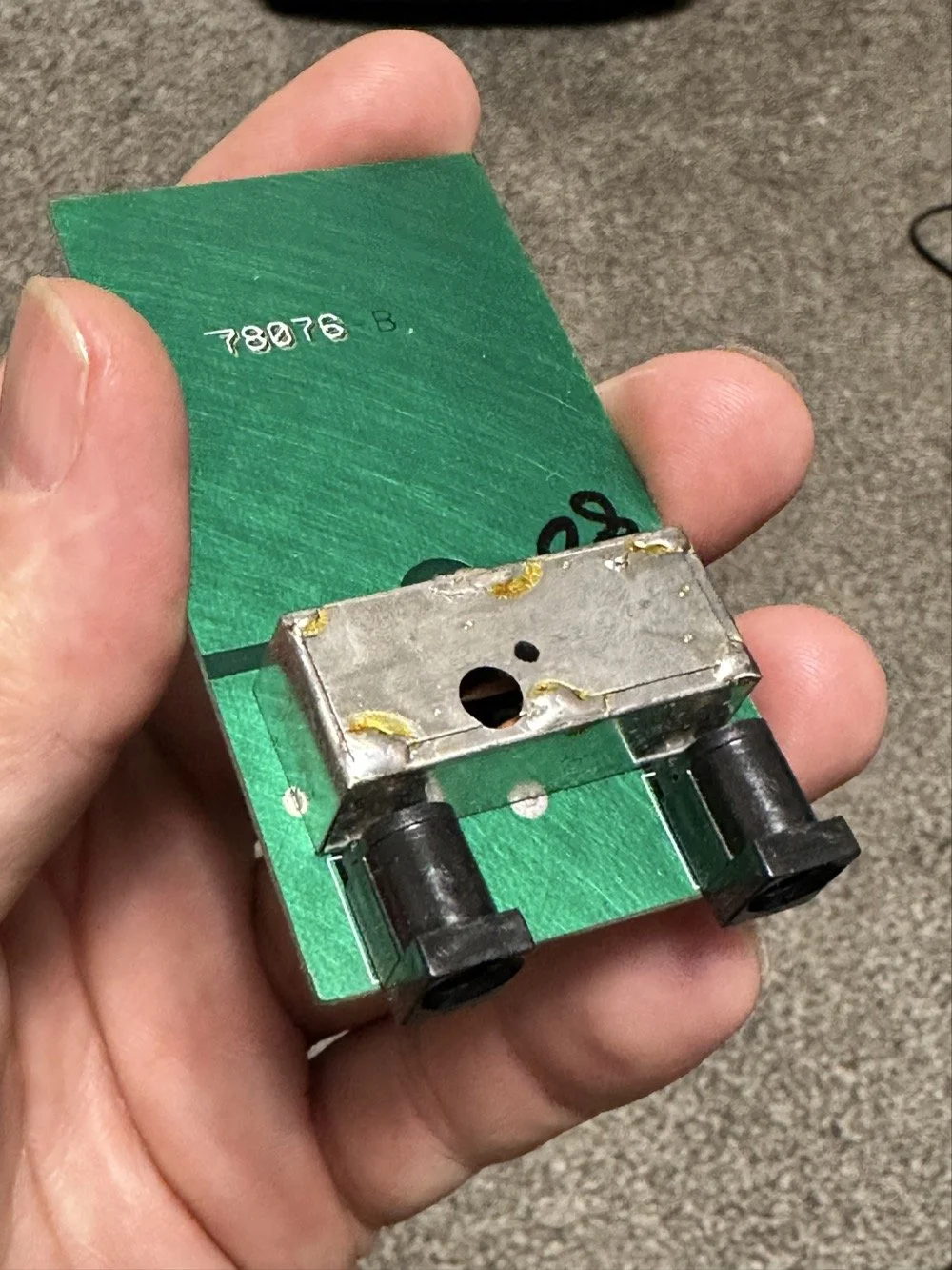
I took another measurement with the nanoVNA and decided to remove the inductors and measure them with the LCR meter to see what it said they were. Turns out they were right on spec from the owners manual chart of 2.5uH each. At least that is what it looked like I read on the meter…haha. So I decide to remove an arbitrary number of wraps from each core (3 wraps to be more precise) and take another measurement to see what I had then. The meter showed them at 1.8 to maybe 1.9uH after pulling three wraps off. This put me right in the middle of 80 meters (2.5uH) and 40 meters (1.4uH) about perfectly. So I trimmed off the excess wire, scraped off the enamel so the solder would adhere to the copper and soldered them into the board.
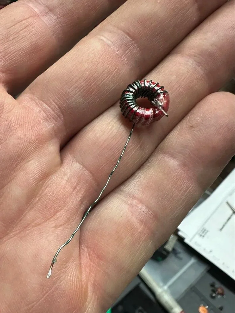
Back to the nanoVNA for another round of measurements to find it still wasn’t where I wanted it to be. The frequency was still pretty low at the roll-off point. I then decided to look at the capacitors to see what they looked like. This is when I noticed that the band module had already been modified somewhat as the center cap was sitting at about 850pf already and not the 1500pf it was supposed to be. I also found that the two shunt capacitors on the ends were also different from the 80 meter module for some reason. I pulled these back to 470pf each and checked it again and now the band pass was in the 6 mhz area, this should be far enough away from the operational band to keep me from having problems so I put it all back together and then checked it into the dummy load.
Success! I am seeing over 120 volts peak to peak coming out of the radio! Woohoo! I couldn’t believe it! I had full power coming out on 60 meters finally! This was a real special moment for me to be honest with you. After this, I reassembled the shielding on the filter network and cleaned up the solder flux and put the module back together.
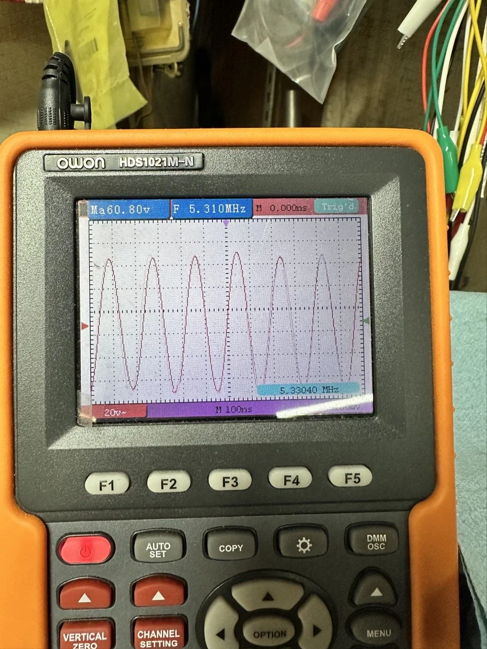
With all that done, all that is left is to set it up with an antenna and make some contacts with it…
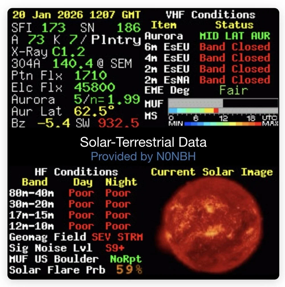
Yeah…about that… There seems to be a major solar storm coming in and has been since the previous day. This is a big deal as you can see from the report. It has shut down radio for most operations. I did call CQ for a while and at one point I heard WY7EE calling CQ but he couldn't hear me. Figures. I did turn up on the RBN so the signal was getting out to some degree in the evening. That was kinda awesome to see as well. I know I have signal going out too as the wattmeter is showing 40 watts forward power. (Remember I de-tune my Scouts to pull some load off the finals since they are getting old and I don’t relish the though of having to replace them for a 10 watt boost in power output) 40 watts will do just as well as 50 from what I have seen in the past… anyway.
The next day we had the storm to start fading out a little and I loaded up the webSDR on my computer and listened for my radio on the Northern Utah listening post. Once the time was late enough, I started hearing my signal on the webSDR! I recorded it and posted it to my YouTube channel as a short if you want to go listen to what I could hear. This is the link.
Link to video about 60 meter signal
Like I said, I am going to revisit the band pass filter for the IF again when I get back into town. I think that can be improved a lot. (my current design is too broad banded in the pass band to make me happy, I want to clean that up some more.) I will write that up when I get the chance to work on it—read Part 4 for the IF filter redesign. Thanks for following along on this little adventure and I hope to hear you on the air at some point. Maybe you will work me on 60 meters with my Scout…maybe…
73 and get out there!
All four parts are here:
- Part 1: Initial Conversion and Filter Design
- Part 2: Crystal Selection and Mixer Circuits
- Part 3: Field Testing and Troubleshooting
- Part 4: IF Filter Redesign (this post)
You can help support this website by using these Amazon Affiliate Links:
QRP/Portable Radios:
Antennas & Tuning:
CW Equipment:
Power & Accessories:
Organization & Transport:
BONUS ITEMS
WK4DS
David
![Converting Ten-Tec Scout 555 to 60 Meters: Complete Band Module Modification Guide [Part 1]](https://images.squarespace-cdn.com/content/v1/5d17806ce65eba00011667cb/18e0d4d9-ed31-466a-884c-4a94776d9a58/IMG_1197.jpg)
Converting Ten-Tec Scout 555 to 60 Meters: Complete Band Module Modification Guide [Part 1]
You see it was starting to look pretty daunting since I didn’t understand what the reason for the odd frequency crystal was and that there were 4 tuned filters in each band module. Also the crystal value just didn’t make sense on the surface.
When I first decided I wanted to make a band module for the Ten Tec Scout 555 that was able to get on 60 meters, I had no idea what really was involved.
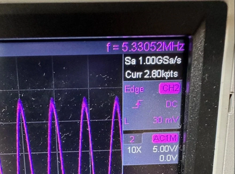
A little backstory here is kinda needed, you see the Ten Tec Scout 555 has become one of my favorite radios for POTA operations and I even find myself setting one up in the shack to tinker with from time to time. I own 3 Scouts and 2 Argos at the time of this writing if that tells you anything. I don’t know if it is the simple elegance of the radio or the fact that it can operate on almost all of the HF bands in such a small form factor, but I love it. Well there are a few things for sure that draw me to this radio like the fact that these radios have the now infamous Ten Tec full QSK (full break in) keying. This keying works flawlessly too by the way. Another reason for such love for these radios is the amazing receive they have even for such a compromise design. With headphones (or even those little earbuds), it is pretty easy to hear stations in the edge of the noise floor and make contact with them.
Well, if you noticed I said… almost… all the HF bands… This is because we have been granted, by the IARU, some space in the 60 meter band as secondary users.
Some of this band space is open to use with power levels up to 100 watts too. (There has been a recent change that modifies the allocation to allow a bandwidth section that is non-channelized but limits the power to 9.5 watts ERP so play in this area carefully. Basically this new region is a QRP only region for now.) Aside from that though, the Ten Tec Scout 555 can operate quite legally in the other 4 sections… or it could if… there was a 60 meter band module… You see this 60 meter band allocation happened after the Scout 555 production run had ended, so Ten Tec never made a factory band module for the 60 meter band that I am aware of.
I started this journey by digging through the owners manual for the Scout as Ten Tec always shipped complete schematic diagrams with their radios. Sometimes there would be missing insignificant data, but you could trouble shoot the radio just fine with them. Once the radio diagrams were located, I started looking at how the band modules made it change bands.This turned out to really be quite simple but I was missing one or two critical values. You see the Ten Tec Scout 555 band modules have a crystal in them and the frequency on the crystal didn’t make sense…at first.
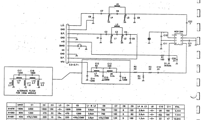
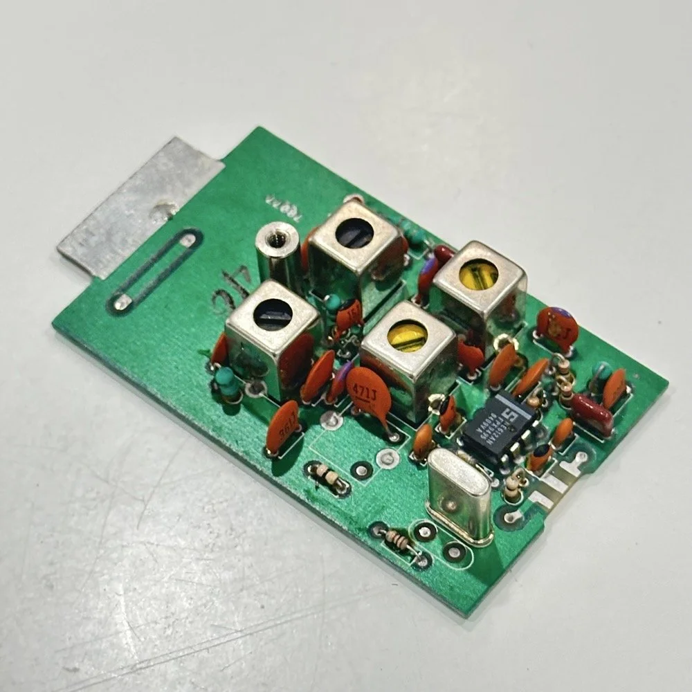
Above is the schematic and a photo of the board that goes with it showing the crystal that I couldn’t understand. This is what tells the radio what band it is on. Looks pretty straight forward at a glance, doesn’t it? Well look at that XTAL value at the end of the chart for 80 meters. Yeah, it takes a 7.444 mhz XTAL to get to the 80 meter band. So I figure the PTO is something like 3.0 mhz so it can get the first negative harmonic when mixed or something like that…nope…turns out I was totally wrong…
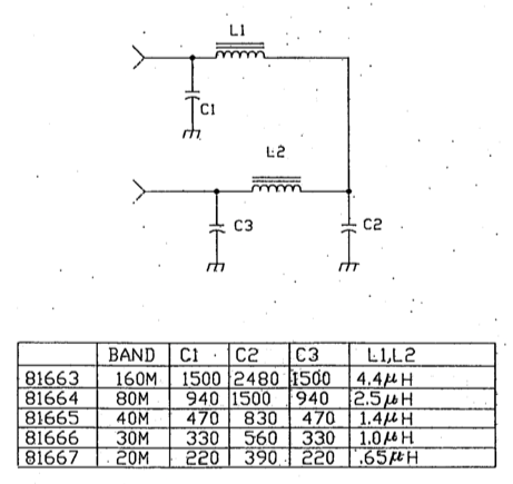
This is the other half of the band module. A classic low pass LC filter and that’s all. This is the output filter that the 50 power amp sends the RF to before it goes to the antenna. Below is what this part of the module looks like. These inductors and capacitors are shielded as they are delivering and filtering considerable power and could interfere with the small voltage levels on the other board that sits right beside it if they were not in the “can” or otherwise known as a ground shield. I don’t know why there is a hole in the shielding either as there is no adjustable parts inside the “can”. I chose this particular 80 meter band module for another reason as well. I have been inside this filter circuit before. When I acquired this module, the fellow I got it from told me it was dead and gave it to me. Turned out to be a broken lead on one of the inductors in this can. It took me a while to desolder this monstrosity to be able to access the parts inside of it. But persistence paid off as I was able to get it repaired and back in operation. I took a lead cut from a transistor and soldered it to the wire on the inductor and simply re-soldered it to the board and it came right back to life. So if you have a module that just stops transmitting all together, I recommend you pull the lid here and look at the inductors to see if one is broken free from the board, that might be all that is wrong with it. I also hot glued the toroids in place to help prevent this from happening again. Anyway, back to the project at hand…
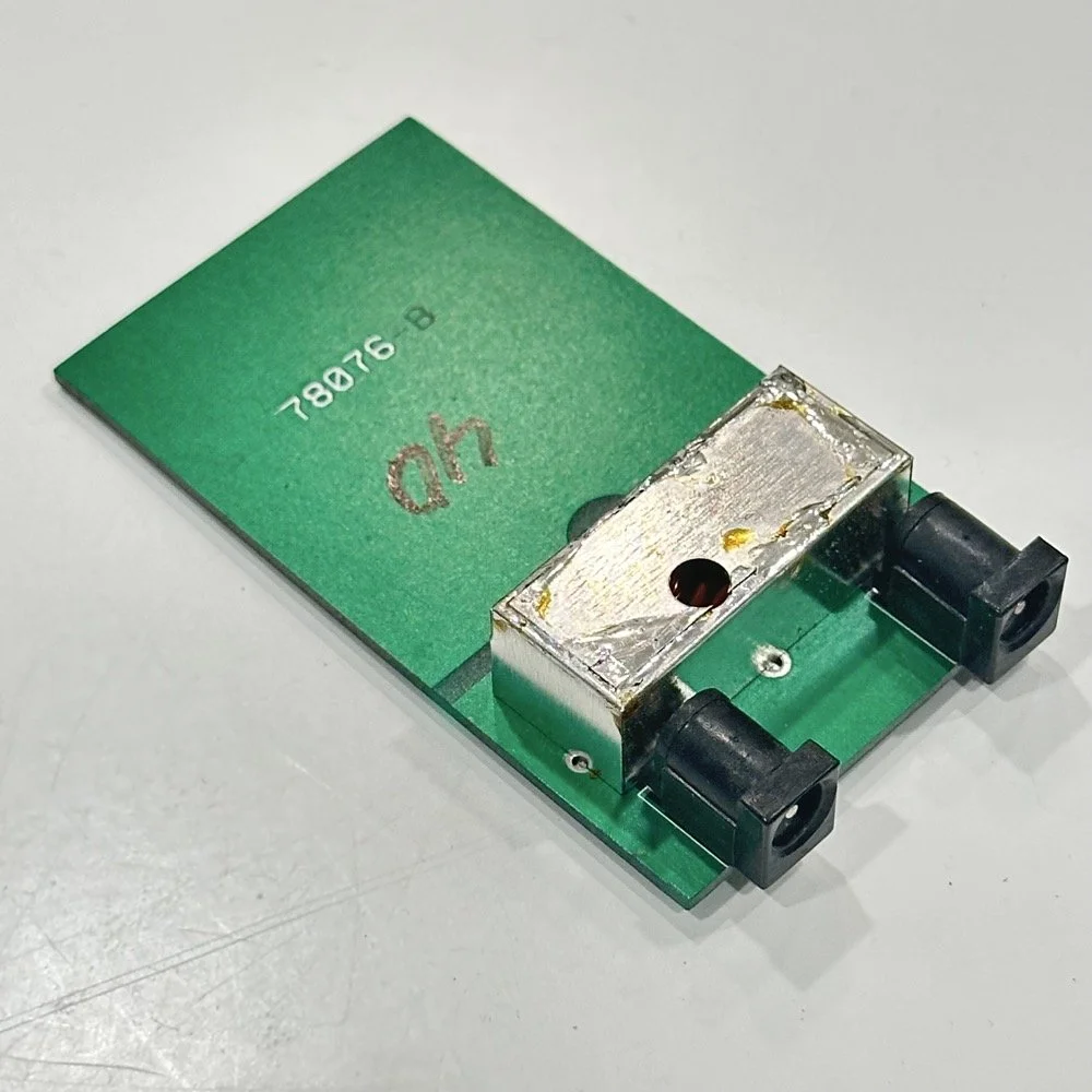
I also looked inside several band modules to see what the differences were and I found some interesting things when I did. For starters, the 10 and 12 meter band modules both use the same circuit boards. They just leave out the second crystal and the switch parts for the second crystal and put a crystal in it for the 12 meter band only when configured for 12 meters. I guess, to be fair, I should have also figured out how the PTO worked as well then I could have figured out the reason for the odd crystal values, but here we are…
Another thing I found was that the engineers at Ten Tec used whatever circuit board blanks that they had on hand to build the band modules apparently. I say this because I found 10m circuit boards (the ones meant for two crystals and the switch) fleshed out with parts to make them into 40 m band modules. (Like the one in the photo above) They apparently just used whichever ones they had on hand at the time. Needless to say, what I thought was going to be simple was starting to turn into a pretty major endeavor.
You see it was starting to look pretty daunting since I didn’t understand what the reason for the odd frequency crystal was and that there were 4 tuned filters in each band module. Also the crystal value just didn’t make sense on the surface. The values were all over the place. I was about to throw in the towel calling it just too complicated, even though the parts count in a band module is really low…till I found two things. One was I looked up what the “555 timer” on the board actually was (Here is a hint, it aint no timer) and the other was NA5N’s website.
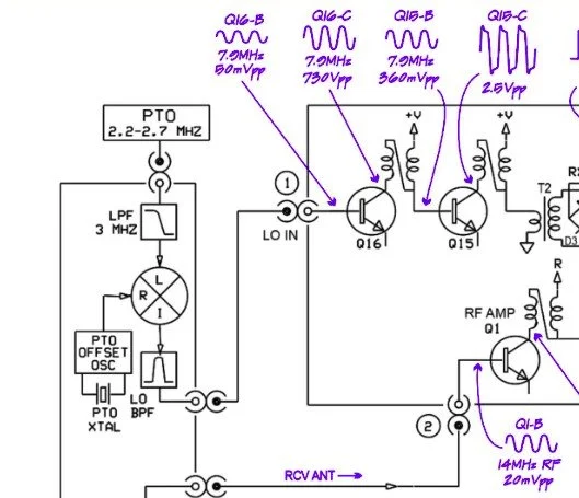
Excerpt from NA5N’s website showing the level of detail these drawings contain.
NA5N’s Scout 555 page is a figurative gold mine of information with just plain cash money piled on top of it, (just to drive this point home take a look at the piece above I grabbed for reference). I can not thank him enough for this information as without it I would not have been able to get this project working as quickly as I did. He also has some really interesting mods he has done to his own radio as well. If you want to perform his mods on your Scout, he gives you detailed information on what is done and literally how to do it…step by step almost. The greatest part of his page though is his info graphics he has built and placed there. These graphics show all sorts of information that the radio schematics leave out.
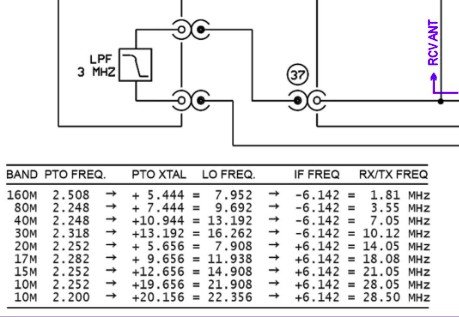
This and MUCH more is available on the NA5N website.
Things like the frequency path (pictured above) through the radio in a chart so you can understand how the engineers at Ten Tec arrived at each band frequency with these plug in modules and a PTO. Complete with oscilloscope test point and what you should be seeing at these points! Like I said, a gold mine buried in cash money…
Based on his chart I went through the band module and looked at the filters for the various circuits and decided (more like assumed based on the values of the parts) that I could simply re-tune an 80 meter module and “push” it up to 5.3305 mhz easily enough and without too much fuss…nothing could have been further from the truth.
So I start tinkering with the filters and piping them through the nanoVNA into the s21 input so I can see the filter shape and all is well from what I can see. Turns out the low pass 80 meter band module filter cut off frequency was about 5.5 mhz or so to start the rolloff so the 60 meter band was still in the pass band! One down three to go! Next I figured out that the PTO is the same for every module since it is part of the radio and not in any of the modules so that filter also didn’t need any mods. This left two filters to re-tune, just so happens it is the two with the adjustable inductors in them. So I start with the LO BPF (Local Oscillator Band Pass Filter) that filters the signal passing through the radio from the antenna. Why they call it the same thing as the LO BPF that is in the output of the mixer chip is beyond me, but here we are… This didn’t go well as I was not able to get enough adjustment out of the inductor slugs to get the passband up to 5.350 mhz, shoot I couldn’t get it to tune up past 4.5mhz if memory serves me. It was far enough that I couldn’t get it work so I looked at what I had and decided to wind some air-core inductors to a lower value and see what I could do like that.
Well, to be honest, I don’t know how I was so successful here. Maybe it was the sheer audacity in the fact that I was woefully unskilled in building filters for HF or the mind boggling lack of knowledge of how filters work and how to make them, but I got it almost perfect on the first try! I made a couple different inductors by winding magnet wire on a 1/4-28 bolt (that’s a little over a 6mm bolt for the rest of the world) and the threads made getting good tight coil layers easy. I borrowed my friend’s LCR meter and measured them and blissfully declared them good to go at 2.0uH each. Did I mention this is a budget LCR meter and I have no way of knowing what the level of calibration is for this part of the meter? I also learned later that I can measure my inductors with a signal generator and a oscilloscope. Guess who now owns a signal generator as well as an oscilloscope...
Once wound and “measured” in the board they went! I then tinkered with the capacitors till the pass-band looked close to what I thought it should look like. (I had also learned from the wonderful world of youtube that I should see less than 1dB of loss in the pass-band and the 3dB cutoff point is where the filter technically is measured..typically.) As I mention in a bit, I used the wrong kind of capacitors (the little blue ones) to start with, although the module did work like this, I updated it with NPO capacitors ultimately as well.
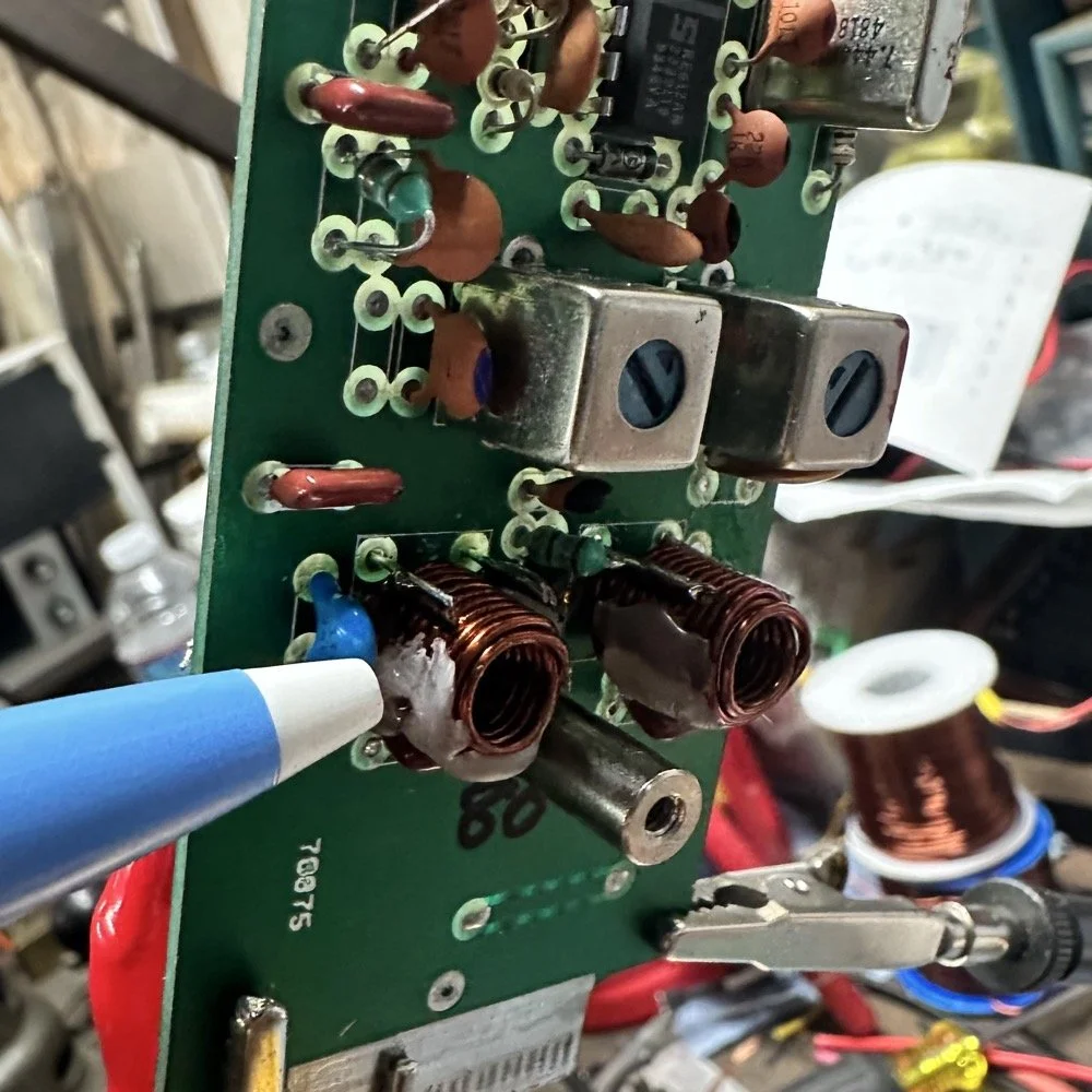
I went down a long path of learning on this project, if you haven’t already noticed from the inserted comments in the story. I have very little formal training in Electrical Engineering, you see I went to a two year trade school back in the 1980s and basically got the “intro to electronics” that EE’s would get before learning things like matching the impedance of the filter to the next stage and to use temperature stabilized capacitors in RF filters so they don’t move the pass-band around when they get warm. NPO capacitors have become my best friends here…lol. A hint for my peeps who also didn’t study RF in college, look at the circuit board above that has the crystal on it. You will see the little capacitors on that board and some have little painted tops on them. This indicates NPO capacitors when the letter designation will not fit. I have now purchased a lifetime supply of these caps off of eBay…haha.
Anyway, now the pre-amp band-pass filter was functioning like it should. One to go…
Tune in for part two where we get into the problems I had to solve to get this module working and how well it works now that I have figured out my mistakes.
Continue reading the series:
- Part 1: Initial Conversion and Filter Design
- Part 2: Crystal Selection and Mixer Circuits
You can help support this website by using these Amazon Affiliate Links:
QRP/Portable Radios:
Antennas & Tuning:
CW Equipment:
Power & Accessories:
Organization & Transport:
BONUS ITEMS
73
WK4DS - David
![Multi-Mode POTA Activation: Penntek TR-35 CW & HT FM on 4 Bands at Sitton Gulch [K-2169]](https://images.squarespace-cdn.com/content/v1/5d17806ce65eba00011667cb/19188a17-7511-4f72-9997-c058e4aec3ea/IMG_7809.jpg)
Multi-Mode POTA Activation: Penntek TR-35 CW & HT FM on 4 Bands at Sitton Gulch [K-2169]
I made over 20 contacts in short order with the Penntek TR-35 radio in bare bones configuration today so that I could get it up and running faster. This radio is a gem to use like this with a simple set of headphones and I dont mind operating like this one bit. This actually makes it easier for me to hear the calls to be honest about it.
Today I wanted to work an activation but I also wanted to grab a couple more bands as well so I hatched a plan to grab some VHF and UHF bands on FM Simplex if my friend KG4WBI happened to be home.
Today was also cold, which you can not see in the photos, but trust me…it was pretty cold. Since it was so cold, I opted to operate from inside the truck and setup a hamstick on 20 meters (I was being lazy today and didn’t explore the other bands) as I wanted to get the activation completed in about an hour since I had to be in Chattanooga for lunch. The 20 meter band will usually guarantee that to happen for me on CW, so I started there.
I noted in the below photo that the one shorter radial had to be pulled taught and the this is where the counter weight was at that held it in position. This is of little consequence other than I am starting to wonder how much capacitance I am getting at the end of the radial from these stainless steel weights at the end of each radial? They are not connected physically to the conductor but are probably capacitive to it through the wire insulation. I used speaker wire for these radials and it has worked really well over the years. I think the next deployment is going to have a smith chart plot where I take the weight off and just tie it off to a stake of some sort. Maybe a chop stick since there is really no tension on these radials. That way I can see just how much capacitance these weights are adding and I can also see if it is helping or hindering performance.


In these two photos I tried to capture something that was of interest to me, today the 20 meter hamstick seemed to tune much better with one of the radials drooped down to the ground and not outstretched like the other one. The one that is pulled taught is the one that is shorter due to the wire breaking over the years and me twisting it back together by hand so I could use it. With this setup, the nanoVNA said the SWR plot was 1.1:1 and it sounded like it on the air! The stations were booming in! I was getting reports back from many stations of 599 with my little Penntek TR-35 radio too!

Once I got everything setup and tuned, I hopped on 20 meters CW to see what I could scare up. Well that turned out to be a great idea as i quickly had a good pileup going and had great fun working through it.
I made over 20 contacts in short order with the Penntek TR-35 radio in bare bones configuration today so that I could get it up and running faster. This radio is a gem to use like this with a simple set of headphones and I dont mind operating like this one bit. This actually makes it easier for me to hear the calls to be honest about it.
Being cold like it was today, I decided to operate in the truck so I could stay warm and could feel the key in my hand unlike the trip to DeSoto Falls state park recently…lol.

Once I was finished with activating on 20 meters CW, I thought I would try to work my friend KG4WBI who lives a few miles away from this location. I knew he had the ability to work me on all three VHF and UHF bands that my HT can transmit on, so I hopped on my trusty HT and gave him a yell on his repeater the KG4WBI/R 1.25meter machine.
He was, in fact, home and he was more than happy to hop on simplex for a few peer to peer FM QSOs so I could add a few more contacts to the log as well as a couple of new bands as well. In the above photo, I had walked across the parking lot to the building in the background that you can see in the photo above. It is behind the white truck in the antenna photo. This spot gets most of the stuff out of the way so I had the best chance at a contact with a HT. Turns out it worked great on 2 meter and 1.25 meter, but 70cm just would not work from here with all the trees in between us. So I gave up on that band and went back to the truck to pack up and head on to a lunch date I needed to be at.
On my way to the truck I had an epiphany. I could just drive down to the lower lot and walk out to the northern most viewpoint on the canyon edge and it should give me clear enough line of sight to make the contact! I would still be WELL within the park bounds and it was the same UTC day. So I packed up the HF gear and headed down to the canyon rim. Called Roger on the repeater again and informed him of my plan, which he agreed to merrily. So we switched over to simplex again and I put in the 70cm call frequency then called Roger’s callsign and he immediately came back with a 59 signal report! Success!!! 4 bands again!!! Woohoo!
The lower photo is me down by the canyon rim where I made the 70cm contact. Don’t I look happy… lol.

I wanted to share this activation with everyone as it highlights a part of POTA that alot of people overlook. Well, actually two parts… one is that it extends to ALL hambands and the second is that you can absolutely use your HT to make short range contacts on FM and they count just as much as those great distance HF contacts. Dont discount 2 meter SSB either. There is plenty of people there too.
Anyway, it was a great day for radio and I appreciate yall coming along for the ride.
You can help support this website by using these Amazon Affiliate Links:
QRP/Portable Radios:
Antennas & Tuning:
CW Equipment:
Power & Accessories:
Organization & Transport:
BONUS ITEMS

Elecraft T1 Antenna Tuner Review: Field Testing with 41' EFHW at DeSoto State Park POTA
I wanted to put the Elecraft T1 automatic antenna tuner in “remote” location mode to experiment a little with it. This meant placing it at the antenna feed point (that is the BNC to Banana plug adapter you see below. I simply tied the 41’ wire to the red and the 9’ counter poise wire to the black and then ran a COAX from ABR Industries to the radio. I like this coax as it has the common mode choke preinstalled so I dont have to add my other one to the system.
I finally bit the bullet and bought me one of these amazing little tuners! The Elecraft T1 automatic antenna tuner is a marvel of modern engineering and I dont know why I waited so long to get one. I took it with me today to test out and see if it would do what I needed…

Today saw me at DeSoto State Park which is located atop Lookout mountain in the NE corner of Alabama. This park is beautiful an was built during the Great Depression by the CCC (Civilian Conservation Corps) and most of that stone work is still there today. The photo below shows the original entrance to the park and the stone work at the entrance is still there. Today, you enter the park from a different road for most stuff but this road it still open to use and I love going this way just to see these vintage masonry works.
If you are interested in learning more about this park just follow this link to the State park website.


Once on location, I set out to put a 41’ random wire into the nearest tree to the truck so I could tune it to all four bands in the Penntek TR35 radio if I wanted to and kept me from having to dig out the hamsticks and all that hardware. I tied the lower support rope to the door handle of the truck them threw the line over the limb I am pointing to in the above photo and got almost all of the antenna in the air before getting into the branches. It was not shorted to anything, but it was in the branches so I was glad to have a tuner handy to dial it in.
I wanted to put the Elecraft T1 automatic antenna tuner in “remote” location mode to experiment a little with it. This meant placing it at the antenna feed point (that is the BNC to Banana plug adapter you see below. I simply tied the 41’ wire to the red and the 9’ counter poise wire to the black and then ran a COAX from ABR Industries to the radio. I like this coax as it has the common mode choke preinstalled so I dont have to add my other one to the system. This cleaned up the install greatly, but did create one little problem… I had not made up a remote “tune” switch yet so I had to get creative with the tuning process. Since the whole thing was on the truck bed cover, I was able to get the CW key over to the tuner so I could key the transmitter and hit the tune button at the same time.
I already have a plan on making a cable that will allow me to tune the antenna remote from the radio in the future.I will share that once I get it put together, but rest assured that it wont be a long time…lol.

I setup the whole shebang today with my homebrew S meter and the auxiliary system box I made up for the Penntek. You dont know how hard it is to get the display to show the whole frequency during the daytime with an iPhone. HaHa. The refresh rate and the shutter speed are so different that you have to time it to get the whole number to show up. You can see the Elecraft T1 in the background where I had it tied to the antenna. You can also see how I have just slid the key over to tune it for the next band change as well. If you will simply plug the paddle into the straight key input, one of the paddles will act like a straight key allowing you the key the transmitter for tuning purposes.
To be honest, I have used this input in the past when I was trying to use a cheap eBay paddle I had bought to test out for travel. One arm literally broke off and I laid it on it’s side and used the other paddle like a straight key to finish the activation. You do what you gotta do I guess…
Another thing is that it finally turned off cold here. it took it till mid November to find us, but winter is here now and it was kind of all at once too. Like last week it was in the high 60s and low 70s and now it is in the 20s and 30s all day. The cloak in the sun is wonderful though and will keep me warm just fine for things like this. This cloak is make of wool so it is incredibly warm and can quickly become too much if I am active much at all.


Today also saw the deployment of the Gemini travel key as the Penntek has two keyer memories and I dont need the PicoKeyer to work this radio. I could still use the PicoKeyer if I just used the straight key input, but the internal memories do all I need and I like have them in the radio. It just makes the whole system smaller an more compact.


I know that I failed to number the contacts, but this is because I had such a strong run on 20 meters and didn’t have time to write down the numbers. It is over 40 contacts and that is a great day for me in the field! Once I moved to 17 meters I could have wrote them in, but at this point I didn’t see any reason to start so I just omitted them this time. It didn’t matter as I still have a great time and the hunters seemed to enjoy the day too. Thanks for following along and a I hope to see you again soon!
You can help support this website by using these Amazon Affiliate Links:
QRP/Portable Radios:
Antennas & Tuning:
CW Equipment:
Power & Accessories:
Organization & Transport:
BONUS ITEMS
72
WK4DS
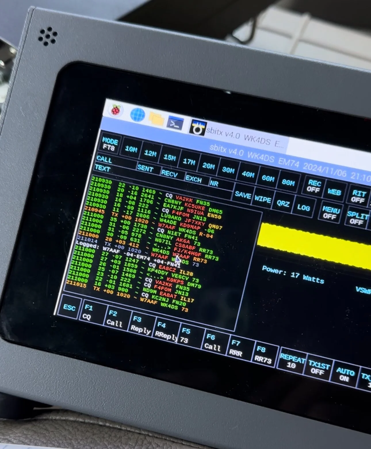
sBitx V2/V3 CW Problems: Why I Switched to Ten-Tec and Penntek for POTA Operations
When I first got this radio, I found it had some keying problems on CW but I just adapted to them and used it anyway. These problems are in how the software monitors the CW circuit and keys the radio and such. Turns out that as the radio heats up, the problem tends to get worse causing me to have to slow down the keyer to be able to send accurate code. Even with these tactics, I still send many mistakes towards the end of an activation due to the lag in the keyer.
I have an interesting relationship with this radio…

When I first got this radio, I found it had some keying problems on CW but I just adapted to them and used it anyway. These problems are in how the software monitors the CW circuit and keys the radio and such. Turns out that as the radio heats up, the problem tends to get worse causing me to have to slow down the keyer to be able to send accurate code. Even with these tactics, I still send many mistakes towards the end of an activation due to the lag in the keyer.

The reason I currently dont use it for SSB is the audio is terrible and I need to trouble shoot that on the bench to see what is going on there. At first it had a weak microphone element so I made a preamp to correct for this but it still doesn’t seem to work all thatwell. Based on all this, I have not used SSB. (I do plan to revisit the SSB circuit to see if I can get it right)
As I also own several portable Ten Tec and Penntek radios that work wonderfully for SSB and CW, I threw in the towel and just started carrying one of those as well as the sBitx. It doesn’t take long to change out the radios since they are so small and light and I really like the break in on Ten Tec radios (the Penntek has wonderful break in too). Another huge plus is that the filtering on the Ten Tec radios is much better than the sbitx in my opinion. Now to be fair, the sBitx filtering is good, but the Ten Tec radios are just better. The Penntek TR-35 suffers the same problems that the sBitx suffers from. Strong, nearby stations will dull the receiver sensitivity.

What I have found that helps in the scenarios is to simply move. There is nothing an overloaded front end can do to help this problem. I do like the features that are available in CW on the sBitx though. Things like the memories and how easy they are to employ is awesome. Another thing is the waterfall is real nice that runs right alongside the CW decoder which has helped me a couple of times. I dont watch the decoder much, but it is nice to be able to see it match what I copied at times for call signs and such. Another great thing about the sBitx is the touchscreen. Not needing buttons is real nice. The only part of the experience that is honestly lacking in CW is the keying problem. Once someone solves this problem, this will be a game changer for a radio. I am still experimenting with different cooling solutions to keep the machine cooler to see if I can get the keyer to work better.

As you can see, this machine makes for a great FT8 field radio. The lack of a need for an external computer is a huge benefit when it comes to this. I just wished the dev team could sort of the CW keying problem this radio has that makes it less than ideal for this application at this time. One thing I plan to do soon is to set it up and see how running QRP power only helps alleviate the heat problem by not running 20 watts on 15 meters and building up the extra heat. This may solve most of my problems but the radio is designed for more transmitter power so I want to access that power.. Another option is to use a keyboard to send the code as it generates the code internally in software instead of polling the IO architecture to get the keying input. This is fun to me too but a nice key is also fun to use. So till the dev team does come up with a solve for the CW keying problem, I will relegate this radio to keyboard CW and FT8 (and maybe even SSB once I address the audio problem again)… But the main reason I wanted the radio to start with was the built in FT8 function that it has, so in that regard I have a great radio that I love to deploy!
If you are considering getting one of these radios, just be aware that it is far from perfect and it is literally made for experimentation. As long as you keep your expectations in reasonable bounds, this radio can be a lot of fun.
You can help support this website by using these Amazon Affiliate Links:
QRP/Portable Radios:
Antennas & Tuning:
CW Equipment:
Power & Accessories:
Organization & Transport:
BONUS ITEMS

Multi-Band POTA Strategy: Ten-Tec Scout 555 + sBitx FT8 on 15m/17m/20m/40m
The location is all too familiar, but I set out to do a sort of special operation today. I wanted to complete a POTA activation using two radios, 3 modes and 4 bands in one sitting. This doesn’t sound like a tall order but since I am operating inside the truck cab, this does involve a little logistics to not just have stuff piled everywhere while I am operating. As you will see in the photos below, I still ran into this problem somewhat, but it was manageable.
Today was a fun day…

The location is all too familiar, but I set out to do a sort of special operation today. I wanted to complete a POTA activation using two radios, 3 modes and 4 bands in one sitting. This doesn’t sound like a tall order but since I am operating inside the truck cab, this does involve a little logistics to not just have stuff piled everywhere while I am operating. As you will see in the photos below, I still ran into this problem somewhat, but it was manageable.
I setup at the disc golf parking lot again, but this time there were quite a few people there and some of them actually quizzed me about what I was doing. One gentleman, Jerry as noted in my log, actually chatted for a good bit about how he has been looking to get into ham radio but the Atlanta area is kinda tough on locating local hams for some reason. I gave him a card and told him to email me and I would give him as much info on it as I could find to get him on the right path…
As you can see in the photos, I set up ham sticks and this time I started on 40 meters FT8. I wanted to get the FT8 portion of my “sprint” if sorts out of the way first as the other two modes were going to be on the Ten Tec Scout 555. I had recently activated with it and it was acting up with chirping on CW and reports of RF noise on my audio on SSB. I attributed this to poor connection of the 20 meter band module as it was fine on 15 meters. Armed with this knowledge, before I left out for the park, I took the radio to the shop and use the Deoxit for gold contacts and a tooth brush to clean the contacts on the band modules. I even wetted one module pretty good and used it to “clean the contacts in the radio by plugging and unplgging the module a bunch of times.
This improvised procedure worked as I got good reports and the CW ran flawlessly as you will see later. Deoxit is magical stuff, if you dont have any, it is work your investment to grab a small can of it.


I really enjoy using this radio for my FT8 operating and with the upgraded finals and RF deck, it runs flawlessly now with SWRs in the 2:1 and even slightly higher range without problem. Today saw SWR levels on transmit of about 1.7:1 and it happily skipped right along making several contacts in a row at one point.
After completing 6 QSOs on FT8 I figured it was time to get the Ten Tec Scout 555 out of the case and see what I could scare up on CW.
The 40m Ham stick that I have must have a really high Q as it is very narrow banded. So I have it tuned for the CW portion of the band and the SWR in the SSB area can be quite bad at times. For this reason, I chose not to hunt any SSB contacts on 40 meters today. Once on CW (this was about 1/2 hour later as this is when I talked to Jerry) the band must have been closing or the band noise was getting so bad that I could not hear many stations. I was able to work Alabama and Tennessee before the call signs faded into the noise. That is something you will learn pretty quick about HF radio propagation, if you want to work closer in stations, use the lower bands, but if you want to reach the west coast from Georgia on a ham stick, use the higher bands like 15 and 20 meters. When 10 meters is open I have worked other continents with ease… Don’t discount those higher bands, they are truly magical.

In the above photo I have the CW key and keyer staged but not connected. The mouse is actually driving the FT8 machine and makes working FT8 so much easier to be honest.

In these two photos you can see what you have to work on constantly. The above photo shows the cable that came with my Ten Tec Scout 555 when I bought it. This is a common issue you will find with home shop made cables. These were stripped back way too far and as I used the cable, the conductors started breaking and I was beginning to worry about blowing fuses.
I happen to own a tool that is designed to remove these pins from the connector, so I am able to dismantle this connector properly. I dismantled it, then took it apart and cleaned it up, properly stripped and re-soldered the pins, then put heat shrink tubing on it all to insulated and protect it better. Now I am not so worried about it either shorting and melting the wire or blowing the fuses and shutting down the activation over something as simple as a cable…


Once I finished on 40 meters and had two modes in the bag on one band, I switched over to 15 meters CW to see what was happening there. There was a contest going on so it was a little crowded and I didn’t understand the exchange so I didn’t jump into the contest, but rather setup on a clear spot and calledCQ and worked a couple of stations there, one station of which is DX!!!
At this point. I got a phone call from KG4WBI about a completely unrelated matter, which we discussed and I told him to fire up his HF rig and we would see if ground wave would make the trip to his house from the park so I could get Georgia in the log as well as a 2nd mode on 15 meters! Well, it worked just fine and we had a great QSO on 15 meters SSB before he had to sign off and go run errands. So having confidence that SSB was going to work better I started calling CQ on SSB.
I got literally zero replies to my calls… so I went hunting instead. I found two more ops that could hear me and I was able to bag a couple more QSOs and these were Park to Park contacts to boot!


These three photo show me installing the band module into the Ten Tec Scout 555 transceiver. It really is that simple to change bands on this radio. Now to be fair, this is not as simple as just turning a knob, but it really isn’t that bad.
To remove the module you pull out the bottom of the little lever on the front of the module and it will pop out enough to be able to slip it out, then you grab a different one off of the pile and stick it back in the slot in the radio. Push it to seat it and then your ready to go.
At this point, I switched over to 20 meters and since the PTO (notice it is not a VFO) was still up in the SSB area, I decided to see if I could hunt some contacts with that mode. I landed one contact in SSB on 20 meters and was happy to get them in the log.
After working the one lonely SSB contact on 20 meters, I decided to give CW a try as well… Remember me mentioning a contest? Well, it was here too. It was going strong as well and because of this I was only able to work one contact on CW as well. If nothing else it netted me another band!

My last stop of the day was 17 meters. The 17 meter band is a WARC band and therefore it is off limits to contesting. Now, to be fair, POTA has been called contesting of sorts, but as of right now it is not considered a contest but is more in the spirit of something similar to a rare DX station activating on the same band and developing a huge pileup there. So I proceeded to hunt me an empty spot (18.078mhz) and started calling CQ.
This is when things literally took off! I netted a whole page of contacts in about a 1/2 hour span of time! What a day! 4th band in the books and I was stoked!!! 17 meters must have been where all the POTA ops had went due to the contest and I didn’t get the memo…lol. The Scout worked flawlessly after the cleaning and I cant be happier now with the old girl.

One of the great things about 17 meters is the propagation is really anybodys call. I worked Hungary at one point as well as California, Alaska and Idaho, then there is a ton of east coast stations too, it was everywhere today on 17 meters. Ham radio is so cool…

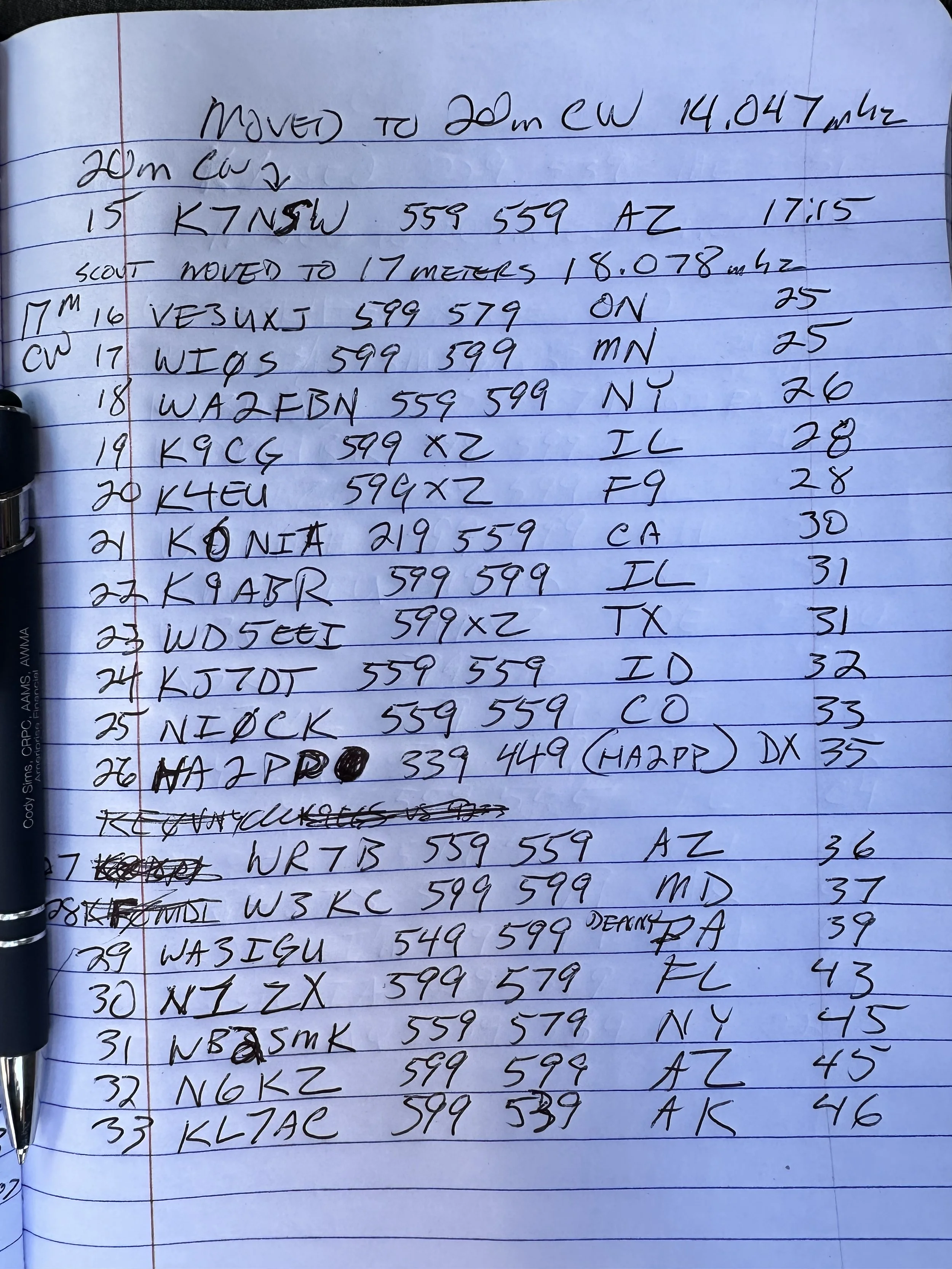

Before closing today I wanted to mention that Aaron KV9L and I have a youtube channel and we just hit 2000 subscribers (as of this writing)! If you are into ham radio and watching videos about it, then we would love for you to come over! I am currently doing a series of short form videos that are teaching CW one letter per day. There is no limit to the number ofd times you can watch them so I am hoping these become long term training aids for people.
Once I get the letters, numbers and punctuation done, I am going to start doing words next. After words will come sentences so we will see how it goes. Anyway, I just wanted to thank the 2000 people that made us as successful as we are!
You can help support this website by using these Amazon Affiliate Links:
QRP/Portable Radios:
Antennas & Tuning:
CW Equipment:
Power & Accessories:
Organization & Transport:
BONUS ITEMS
73
David -WK4DS
![Ten-Tec Scout 555 POTA: 74 CW Contacts at Raccoon Creek WMA [US-9875]](https://images.squarespace-cdn.com/content/v1/5d17806ce65eba00011667cb/fe9e1368-6e59-44e9-9c7e-d01d02e14fe8/IMG_7569.jpg)
Ten-Tec Scout 555 POTA: 74 CW Contacts at Raccoon Creek WMA [US-9875]
As you can see from the QSO map above, the bands were alive and well on this day from Raccoon Creek WMA (US-9875). The calls just kept coming in and I finally had to got QRT, with people still calling, and pack up as I had to meet the wife for a dinner date! I normally clear the little pile up I will draw in and then I can simply power down. I really felt bad about having to shut down with stations still calling me. I now know what those rare DX station feel like… It is surreal to experience that to be honest… especially from Alabama.
Today got so fast paced that I forgot how to do CW properly! Let me explain…
As you can see from the QSO map above, the bands were alive and well on this day from Raccoon Creek WMA (US-9875). The calls just kept coming in and I finally had to got QRT, with people still calling, and pack up as I had to meet the wife for a dinner date! I normally clear the little pile up I will draw in and then I can simply power down. I really felt bad about having to shut down with stations still calling me. I now know what those rare DX station feel like… It is surreal to experience that to be honest… especially from Alabama.
You see, today I activated US-9875 Raccoon Creek WMA and I went at a different time of day. I wanted to spend several hours here today as I dont get over to the area often and I wanted to try to get as many contacts as I could in the afternoon. My goal was 60 QSOs today which is way more than I usually worry about, but like I said, this park is a solid 40 minutes in one direction and I dont go this way too often so I wanted to “make it count” if you know what i mean.
I rolled into the WMA at about 14:30 local time and set out to build the radio down by the Tennessee river. This is a small parking lot at the end of one of the gravel roads into the WMA and a lot of locals come to this spot to fish in the river from the shore. Did I mention it started raining right after I got the antenna setup and I got into the truck? Well, let me tell you, the rain set in and it didnt stop the whole time. I even broke down the antenna and stuff out in the rain today!!!


The above photo shows what the station looks like right before I plug all that stuff in and turn the power on. Everything I need to get on the air is in that pile for both SSB as well as CW. To be fair, I can get by without the Picokeyer and the 1/8 mono to 1/8 mono cable and I could simple plug the paddle right into the radio and it would work just fine. So there is really excess here above what is absolutely needed.
I did get the nanoVNA out and look at the antenna to make sure the rain didn’t do something to it like push it out of band due to the conductivity of the wet earth or what ever. Turns out it was just fine… It was a little low with the water on everything but the null was really close to the bottom of the 15 meter band edge so I used it and didnt worry about it. If you will notice, it was only 1.233:1 SWR at the band edge so it was plenty happy and we never checked it again after this on 15 meters. When I switched to 20 meters, the SWR had moved up to about 1.8:1 or maybe it was at 2:1 but I ran it and as you can see in the log, that didn’t seem to matter at all.

I setup shop on 15 meters SSB for a change and wanted to see what I could get before 15 faded out, but I noticed almost immediately that the ALC light wasn’t coming on at all when I would transmit audio. This lamp should just blink on the energy peaks but it wasn’t coming on at all. I messed with the mic gain and nothing. I did notice that I could wiggle the cord at the plug and it would make all sorts of stuff happen. This pointed me to the connector being faulty somehow but workable to some degree.
I made a few contacts with it like this and basically yelling at the radio would barely get the ALC to illuminate. I asked the last person for a report and they told me the audio was muffled and weak. Armed with all this knowledge, I decided to open the connector and see if a wire was broken. Well, they were not broken…but they were also not connected either. There were two cold solder joints from the factory…figures. I got a pretty decent photo of the green wire in the below photo. Well…that shuts down the SSB portion of this activation so onto 15 meters CW!

The 15 meter band has two things that make it unique. It is quieter than the lower bands for me and the “skip distance” is MUCH further with mobile, or improvised antennas. I didn’t make many CW contacts on 15 but check out the locations! Washington state is pretty common for me on 15 meters, in fact the entirety of the western United States is easier for me to work on 15 meters during the day. But a lot of people apparently don’t know this so lots of times the band will be open but there wont be anyone on it. Case in point today, I worked 4 ops in 11 minutes of calling CQ.
After vacuuming the bands of CW ops, I moved to FT8 to see what was happening and this is my “yardstick” of how open the band is. Turns out it was REALLY open! 15 meters FT8 netted a nice dozen contacts and got me almost half way to my original goal of 60 QSOs! This didn’t take long either and just goes to show that the higher bands are great if you will just go check them.

I had switched radios to use the sBitx V4 (I did the software upgrade and got some new features like the color coding of FT8 information you see below) You can also see that I was transmitting with 17 watts too. This is not precise, but it is close and I use it for my logbook notes.

After finishing on 15 meters I moved down to 20 meters to finish out the day. The sun was starting to set at this point and I knew 20 meters would serve me better at this point. after hunting W9XT, I set up shop on a clear frequency and started calling CQ, this is when things got a little crazy. I had a nice little pileup form pretty quick that took me about half an hour to clear, then nothing… It must be band fading at this point as the stations just vanished. I figured I would switch over to FT8 for a few minutes at this point too and see what I could get in that mode. I didn’t mention that I used the sBitx for CW at this point and to be honest, I dont think I will use it for CW seriously till there is a software change to make it work better. If you try to use it much past 18WPM it is like it fights you and induces mistakes for some reason. The people smarter than me in the email reflector seem to think is has to do with how the software scans the inputs on the radio, but I do know it will induce mistakes in your sending if you are not very attentive and send a very specific way. It will work if your careful and go about 18WPM max. I can use a keyboard to send CW but that really isnt all that much fun to be honest.
I struggled with FT8 today on 20 meters for some reason. The QSO could not complete to the 73 so it would not autolog the QSO. It would also not finish the exchange many times either. I could get it to send the signal report then they would send back and they would just get stuck in that step and never move past it. It got really frustrating towards the end, but I did manage to net some contacts here too.
At this point I had made 48 contacts which is a phenomenal day out for me, but I wanted 12 more to have that 60 that I started out my goal with! So at this point I move back down into the CW portion but this time on the Ten Tec Scout 555 instead since the CW mode on it works beautifully.


It took me a couple minutes to switch the radios out and to find a clear frequency and get started, but once I did, it didn’t take long to get a HUGE PILE UP going!!!! I got so excited during this part that I was racing the clock to see how many I could work before having to shut down the radio and go home as I was almost out of time. I started rushing the closing and it was here that I got sloppy with my CW. You see, I normally use QRP power levels for the most part, just the sBitx and the Ten Tec Scout are QRO by the rules and the sBitx is borderline to me. I will usually turn the power down to 5 watts or so anyway to preserve the finals in the radio but today I had the Scout and it is set at 50 watts and is not easily field adjusted from that power level.
As the pile up raged on, I got so lost in the process that I started sending 72 intermingled with contacts getting 73 instead and finally someone stopped me and asked why I am signing both modes and this is when it hit me. I had been running on autopilot about half the time just logging contacts and the muscle memory would just send the 72 and I would not even think about it. I would then called QRZ and get another call, rinse and repeat… Here is the next problem for me. My ragchew copy and my POTA copy are very different levels. He sent me the message at the speed I was working POTA contacts. Your brain will learn how to copy the formatted style exchanges without even thinking about it. I know that I am going to get a two letter state after the signal report and I can copy callsigns really well for some reason up to about 25 WPM, but send me a full sentence question and it breaks my brain. I cant copy half of it without writing it down. I can ragchew comfortably at 18 WPM max at this time, but if you ask me a question about my radio or something that isn’t part of the usual banter in a POTA contact and I am lost… I apologized for this mistake I had been making for probably 20 minutes without even realizing it and it was really close to when I had to leave anyway so I went ahead and called QRT to get the radio put away as it was raining really well at this point too…
To everyone that reads this that I didn’t get to work on this day, I am sorry to have to had shut down the rig and leave, I was having a wonderful time and wanted to stay longer!!!


The moral of this part of the story is dont get in such a hurry that you cause confusion with the hunters, take your time and be sure in what you are actually sending out over the airwaves.
On a brighter note, I got my 60! and 14 more!!! I dont know how long it has been since I got that many calls in the log in one day. Until next time I hope to work you on the air!
Read more Ten-Tec Scout 555 POTA activations:
- [Another Scout 555 POTA post]
You can help support this website by using these Amazon Affiliate Links:
QRP/Portable Radios:
Antennas & Tuning:
CW Equipment:
Power & Accessories:
Organization & Transport:
BONUS ITEMS
73
WK4DS - David

Ten-Tec Scout 555 POTA Activation: 26 Contacts in 15 Minutes CW & SSB Setup Guide
Looking for a reliable POTA activation setup? Here's my complete guide to activating parks using the Ten-Tec Scout 555 transceiver. In this activation, I made 26 SSB contacts in just 15 minutes, plus worked several stations on CW using ham stick antennas and portable power. Whether you're new to Parks on the Air or looking for equipment ideas, this post covers my portable ham radio setup, antenna tuning tips, and real-world activation results.
Looking for a reliable POTA activation setup? Here's my complete guide to activating parks using the Ten-Tec Scout 555 transceiver. In this activation, I made 26 SSB contacts in just 15 minutes, plus worked several stations on CW using ham stick antennas and portable power. Whether you're new to Parks on the Air or looking for equipment ideas, this post covers my portable ham radio setup, antenna tuning tips, and real-world activation results.
My Ten-Tec Scout 555 POTA Equipment Setup
My setup process has gotten pretty streamlined over the years. I pull into the parking spot, grab the Scout case and antenna bag from the truck bed, and I'm usually on the air within 15 minutes. First thing I do is get the hamsticks mounted and run the radials - usually just two per antenna is enough for POTA work. While those are getting situated, I'll set up the radio in the truck cab, connect power, and do a quick SWR check with the nanoVNA. If the SWR is under 2:1 I'm happy enough to start making contacts. The key is keeping it simple - I've learned the hard way that complicated setups mean more things that can go wrong in the field. Harbor Freight cases have been a game changer for organizing everything too. Everything has a place and I can just grab the case and go.
Today saw me use the Ten Tec Scout again to great effect. Below is the case I carry it in showing the full compliment of band modules (I keep one in the radio and today that is the 20 meter module). Under the radio is the power cable in a pocket just for it and next is the spot for the microphone in a more permanent role. You can see the impression from where it sits in the case currently. This Ten-Tec Scout 555 POTA activation demonstrates why this radio is popular for portable ham radio operations.
These hard cases come from Harbor Freight and make wonderful travel cases for my POTA radios to be quite honest about it. I need to get two more and kit out my Ten Tec Argonaut 5 and my Penntek TR-35 and the set will be complete. The Argonaut has a nice hard case, but it is really large and kinda hard to maneuver with. I thought it would be a great kit for POTA and it does work, but I would really like something different… As an aside, I store the owners manual to each radio behind the lid foam on all of these. That way I have a instruction book should I forget how to do something obscure that I dont use all that often.

My Ten-Tec Scout 555 travel case showing all band modules for POTA activations

Scout 555 band modules - simple to swap for different frequencies during activation
I have not dismantled a band module to see what all is inside it but there is a good bit of stuff going on in each one. They are about 3” long and the circuit board goes all the way to the front. So there is plenty of widgets inside them to make the magic happen.
Today, I only used the 15 and 20 meter modules as I was being a little lazy and only put out radials for these two ham sticks. A quick SWR check with the nanoVNA and I was off to the races.
N3ZN straight key with Picokeyer adding memory functions for CW POTA activations
POTA CW Equipment: N3ZN Key and Picokeyer Setup
The above shows my CW key and keyer. The key is made by N3ZN and if you have not tried one then I highly recommend them. It works beautifully for me. The keyer is a Picokeyer from Hamgadgets.com and works way better than it should for what it costs. Since Ten Tec radios traditionally dont have memories for the CW keyers, this is the way to have those memories really easily. For Parks on the Air activations, having a portable CW key with and a electronic keyer with memory functions is essential (at least to me it is…).
Operating SSB on POTA: Hand Mic and Voice Contacts
The next thing I did that was out of my usual character is to get the hand mic out and work some SSB today as well. It worked OK, but there were times when the audio was odd and I would get little hints to something being wrong but all in all it worked fine.

Hand mic for SSB operation - made 26 contacts in 15 minutes with this setup

Quick SWR check with nanoVNA before starting the POTA activation
Choosing a POTA Activation Location
When I scout out parks for POTA activations, I'm looking for a few key things. First, low RF noise is critical - no nearby power lines, businesses with switching power supplies, or heavy traffic. This park checked all those boxes and then some. The parking lot being empty is a huge bonus as it means no ignition noise from cars starting up or idling nearby. I also look for parks that allow me to set up antennas without disturbing other visitors. Some parks get really busy on weekends, so I'll often activate during weekdays or early mornings. Having good cell coverage helps too, though it's not required - I like being able to spot myself on POTA.app without relying solely on the Reverse Beacon Network. This particular spot has become one of my go-to locations because it's quiet, accessible, and the park staff are friendly to hams.
As per my usual outings, I had the place to myself today with only a couple of cars rolling by during the entirety of my activation. I like it like this though as there is no ignition noise to deal with or inverters making RF hash, just the peace and quiet of the park and my radio chattering in the truck. During this time of day, the sun will beam into my door if I roll down the window beside me so I usually just roll down the other three and the one beside me just a little so the air still moves through the truck taking away the heat from the radio and making it nice and pleasant.
Just look at that parking lot all for me! HaHa! That never gets old! There is just something magical about the peace and quiet of a park like this.

Perfect POTA location - empty park means no ignition noise or RF interference
Ten-Tec Scout 555 CW Operation Tips and Side Tone Settings
A few operating tips I've picked up over my POTA activations - start on CW if you can work it, as the Reverse Beacon Network will auto-spot you and save you from needing cell service. Once you've got 10 contacts in the log, switch modes or bands to see what else is happening. Don't be afraid to QSY (change frequency) if things go quiet. During this activation, moving from 15 meters to 20 meters made all the difference - 15 was fading out but 20 was on fire. When you get a pile-up like I did on SSB, just work them as fast as you can log them. Don't worry about being perfect, just get the call sign and signal report down. You can clean up the log later if needed. And always, always bring spare coax and adapters. Murphy's Law is real in the field!
Something I learned today that is different between the Argonaut 5 and the Scout is that I have to use the key jack to make this radio transmit a side tone in CW. I can key the transmitter with the “mic jack cable” that I made for the Argonaut 5 but it wont produce a side tone with the Scout for some reason. So I instead used this port on the back of the radio to get it to work right (see photo below). Another special thing about this radio to me is that it has a Curtis keyer chip in it and you can plug a set of paddles directly into it and it will work as you would expect, but it is in a different port… Go figure. All these options are hot all the time too. Plug a straight key into it and key it to send CW then you could (theoretically) just pick up the microphone and talk to someone on SSB without changing anything else on the radio. It appears that it is in SSB mode all the time and CW is just the side tone being transmitted instead of the audio from the microphone. This does cause one little issue that a user will notice pretty quickly. The zero beat is the display frequency plus or minus (depending on band) the side tone frequency. The filter is simply a bandpass knob that adjust the filter bandwidth and that is it. A very simple radio that just works.
An example of the side tone offset in CW can been seen in the photo above where I am tuned up on 15 meters. It displays 21.0523mhz but the radio is actually operating on 21.053mhz when transmitting. So if you are near the band edges on say 40 meters CW, just keep this in mind so you are not transmitting out of band. The owners manual even mentions this to make sure you stay compliant with FCC regulations.

CW key jack on Scout 555 back panel - required for proper side tone in CW mode

First page of activation log - starting on 15 meters CW and SSB

20 meter SSB pile-up - 26 contacts in just 15 minutes!

Final page showing all contacts from the activation
POTA Activation Results: 26 Contacts in 15 Minutes
As you can see from the log above, I started out on 15 meters CW and worked several stations there before moving to 15 meters SSB till the band essentially faded out. At that point I decided to see what would happen if I went down to 20 meters SSB and called CQ… Well the log speaks for itself. I made 26 contacts in 15 minutes! This has to be some sort of world record!!! LOL…for me that is… It was wild how big the pile up was and how quick it happened! The people were super nice and courteous and really helpful so I thank all of you that called me this day and I really appreciate you stopping by to say hello! This POTA activation shows what's possible with a simple portable ham radio setup."
Frequently Asked Questions About POTA Activations
What equipment do I need for a POTA activation?
For a basic POTA activation, you need a portable ham radio transceiver (like the Ten-Tec Scout 555, Icom IC705, or the like), an antenna (ham sticks work great for portable use), a power source (battery or vehicle power), some interconnect cabling such as coax and things like that, and a way to log contacts. Optional but very helpful equipment includes: a CW key for Morse code operation, a portable table or chair for comfort, an antenna analyzer like the nanoVNA for precise tuning, and a keyer with memory functions for repetitive CW exchanges. The beauty of POTA is you can start simple and add equipment as you learn what works for your operating style.
How many contacts do you need for a valid POTA activation?
You need a minimum of 10 QSOs (contacts) for a valid Parks on the Air activation. These contacts can be made on any amateur radio band and any mode - CW (Morse code), SSB (voice), or digital modes like PSK31 or FT8. Park-to-park contacts (when you work another station who is also activating a park) count double for hunters, but still count as just one contact toward your activation total of 10. Remember VHF and UHF contacts count too as long as they are simplex only.
What is the best radio for POTA activations?
The "best" POTA radio depends on your operating style and preferences. The Ten-Tec Scout 555 is excellent for CW operation thanks to its clean receiver, simple design, and reliable performance. Other popular choices among POTA activators include the Yaesu FT-891 for 100-watt capability, the Elecraft KX2 or KX3 for QRP portable operation, and the Icom IC-705 for all-mode including VHF/UHF. Choose based on your preferred operating modes, power requirements, portability needs, and budget.
How do you tune a ham stick antenna for POTA?
The easiest way to tune a ham stick antenna is with an antenna analyzer like the nanoVNA, or you can use your radio's built-in SWR meter. Start by adjusting the length of the whip section - make it longer to lower the frequency, shorter to raise it. Make small adjustments (just a fractions of an inch at a time) and recheck your SWR reading. For POTA activations, an SWR under 2:1 is generally acceptable and will work fine, though under 1.5:1 is ideal for maximum power transfer. Anything under 2:1 will not damage your radio though so don’t stress too much over this part.
Can you operate POTA from inside your vehicle?
Yes! Parks on the Air rules allow operation from inside your vehicle, which is different from SOTA (Summits on the Air) that requires outdoor setup away from vehicles. Operating from inside your car or truck is actually quite common during POTA activations, especially in bad weather, extreme temperatures, or when dealing with insects. As long as you and your entire station are physically located within the park boundaries, you're good to go. Just make sure you're parked in an authorized area.
What is the best band for POTA activations?
20 meters is often the most productive band for POTA activations because it provides a good mix of both local and DX (long distance) contacts throughout the day. 40 meters works exceptionally well for regional and NVIS contacts, especially in the early morning and evening. 15 and 10 meters can produce excellent DX contacts when conditions are right and solar activity is favorable. Many experienced POTA activators work multiple bands during a single activation to maximize their contact count and variety. In my activation with the Scout 555, 20 meters SSB produced 26 contacts in just 15 minutes - that's the power of picking the right band at the right time!
Whether you're new to Parks on the Air or an experienced POTA activator, the Scout 555 makes for an excellent field radio.
Have you tried POTA with a Ten-Tec Scout? Share your activation stories in the comments below! If you're planning your first Parks on the Air activation and have questions about equipment setup, feel free to ask.
Want more POTA content?Subscribe to my ham radio blog for more activation reports, equipment reviews, and portable operating tips.
---
## POTA Activation Summary
Equipment Used:
- Radio: Ten-Tec Scout 555 (50 watts)
- Antenna: Ham sticks on 15m and 20m with tuned radials
- Power: Vehicle electrical system
- CW Key: N3ZN paddle key with Picokeyer
- Microphone: Ten-Tec hand mic
- Accessories: NanoVNA for antenna tuning, Harbor Freight case
Operating Details:
- Bands Worked: 15 meters and 20 meters
- Modes Used: CW and SSB
- Total Contacts: 30+ QSOs
- Best Run: 26 contacts in 15 minutes on 20m SSB (that was wild!)
- Setup Time: Approximately 15 minutes from arrival to first contact
- Activation Duration: About 90 minutes total
Key Takeaways:
The Scout 555 continues to prove itself as a solid POTA radio. Simple, reliable, and the receiver is clean even with nearby RFI sources. The band module system makes it easy to swap bands, though it's not as fast as just turning a knob. The big lesson today was remembering which key jack to use for proper CW sidetone - small details like that can save you troubleshooting time in the field. Also, 20 meters SSB was absolutely on fire today - sometimes you just catch the band at the right time and everything clicks.
---
You can help support this website by using these Amazon Affiliate Links:
QRP/Portable Radios:
Antennas & Tuning:
CW Equipment:
Power & Accessories:
Organization & Transport:
BONUS ITEMS
73, WK4DS - David

Rainy day CW POTA is the best...for me.
When I set out to activate a park today, I didn’t know where, but rather, only how I wanted to do it. I have been using FT8 so much lately that I got to missing my little CW only radios.
When I set out to activate a park today, I didn’t know where, but rather, only how I wanted to do it. I have been using FT8 so much lately that I got to missing my little CW only radios.
The Penntek TR-35 CW QRP radio is perfect for POTA
Today saw the re-emergence of the Penntek TR-35 and all the little widgets I made to go with it. I really love this little radio and now I have built an actual travel kit around it so if I wanted to take it somewhere on a plane, the kit will fit in my carry on baggage.
The travel kit doesn’t include the s-meter module or power pack/speaker, but those are “luxuries” anyway. The kit does have everything needed to get the radio on the air and making contacts and that is all that it has. Anyway, let’s get to today!
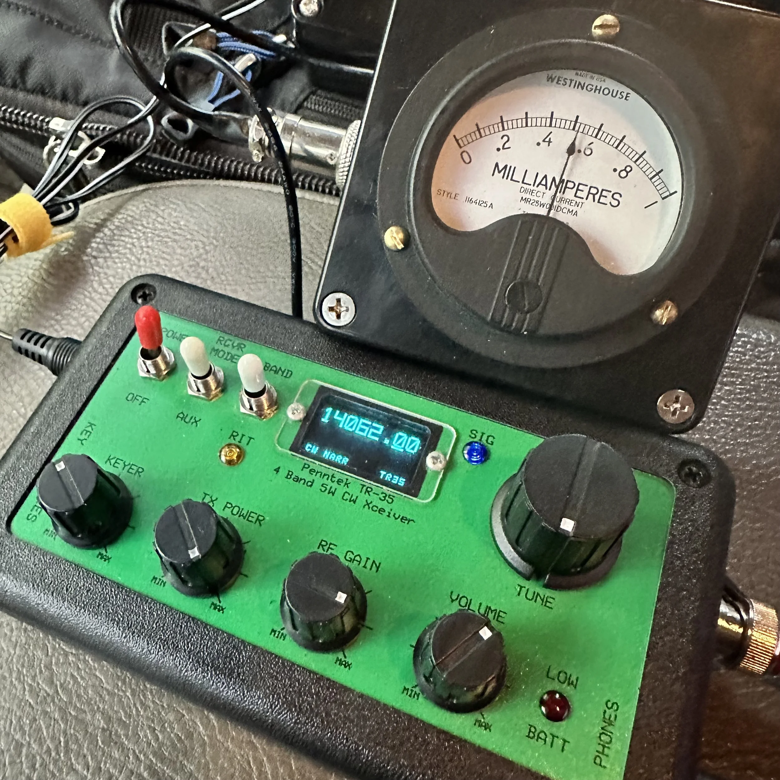
Pictured above is the radio and the “S meter” I built to go along with it. This meter works really well and makes using the radio just a little more fun for me. Is it needed? No, not at all, but that isn’t the point. This needle bouncing around while I copy code somehow is soothing for some reason and I can see how strong the signal is visually as well. I wrote about how I built in in this blog post.
Another thing of note is that this tiny little N6ARA key works REALLY well. Way better than something this simple should work… It actually works so well that it is worth using as a regular key. It is that good. Now to be fair, I dont know what the life of the key would be as it is PC board material so the contact thickness isn’t that much, but these keys do work really well. It takes a while to get it dialed in (read that as adjusted to your sending feel and style) but once you do, it is amazing how well it works. I should have gotten the larger variant, but I had this silly idea about minimalism and because of this, I got the little one.

Getting the key adjusted correctly and then some practice using it and this thing is amazing. Take it from me, if your not super concerned with every gram of weight, then get the bigger unit. It gives you so much more to hold onto that it isn’t even a option for me now. I still have the small one, but I do plan at some point to get the larger case for it.


Getting a spot on the POTA website
I posted this screen shot, of my spot on the POTA website, because I wanted to thank David- WA2OTC for going to the trouble of spotting me on the website while I was at the park without good cellular signal. He even came back to me and let me know that he had gotten the spot on there before moving on with his hunt. Thank you David!
It was really nice to not have to worry about getting on the website and getting myself spotted. You are probably thinking, then how did you get the screen shot? Well, I didn’t have a total black out, but just weak signal, so I simply loaded up the website and waited the 5 minutes or so for it to populate (seriously, I thought it would never load) so I could grab a screen shot for the blog. It would update EVER SO SLOWLY if I left it on the page. This location is a geographical oddity, it is close to the city but in a particular spot where there is terrible cellular coverage for some reason.

Welcome to fall and winter in the south. I have realized over the years that we get most of our water in the winter and I have planned accordingly. Things like the tape on the coax connector below to keep the rain out during an activation… Don’t forget to keep a roll of electrical tape in your car. Another trick I learned in working electrical maintenance over the years is that if you wrap the tape inside out (sticky side to the outside) then it wont leave residue on the cable and it works just as well for this purpose. We used it on factory motor connections so the rubber insulating tape would not stick to the connectors and it make changing the motors so much easier.
This exact weather event is what drove me to build the truck-tenna mount and figure out a power source for inside the truck cab to start with. POTA in the rain can still be fun as long as you plan for it.
The Inside-Out Electrical Tape Trick (From 20 Years of Electrical Maintenance)
I learned this trick working electrical maintenance over the years and it's perfect for POTA rain operations. The standard method that most people use is wrapping electrical tape with the sticky side to the connector, and this works fine for permanent installations where you're never going to take it apart again. But here's the problem for POTA: it leaves sticky residue when you remove it, it attracts dirt and moisture over time, and it's a pain to clean off in the field when you're trying to pack up and get home!
The inside-out method is way better for portable operations. You wrap the tape sticky side OUT, which sounds completely backwards but hear me out! The first wrap still sticks to itself even though it's reversed. It forms a perfect… well, close enough… waterproof barrier just like normal tape would. But here's the magic: when you peel it off after the activation, there's no residue on your connector! You can do this multiple times without any sticky buildup.
So how did I learn this? We used it on factory motor connections in industrial settings so the rubber insulating tape would not stick to the connectors and it made changing the motors so much easier. Motors would run for years in dusty, dirty environments and when it came time to replace them, the tape would peel right off without leaving any mess behind. The connectors underneath would be clean and ready to reconnect immediately.
For ham radio applications, I wrap coax connectors sticky-side-out, cover BNC connections between the radio and coax, and protect any exposed metal from rain. It works perfectly! Here's the actual process: Connect your coax normally first. Start the tape wrap with the sticky side facing OUT (this feels weird at first!). Wrap it around the connector 2-3 times, overlapping each wrap by about half. Press the tape to itself as you go so it forms a good seal. And that's it! You're done and it's completely waterproof…for a little while (long enough to complete the activation).
After the activation when you're packing up, peel off the tape and toss it in the trash.
Just like the tape on the coax connector below to keep the rain out during an activation... Don't forget to keep a roll of electrical tape in your car! This simple trick has saved countless activations from rain-related failures. I'm serious about always having a roll in the truck because you never know when weather is going to change on you!


Another thing that has happened at this location is that someone has cleaned it up… I am guessing the park service since there were chainsaws used…a lot. The cut all of the dead trees out as well as cleaned up all the dead-fall and then mowed the entire site! This is the first time I have seen this happen since doing POTA! The photo below was take just a month or so back.

The Joy of CW-Only Operations
There's something special about CW-only rigs like the Penntek TR-35 that's hard to explain until you've actually used one for a while.
The first thing you notice is there's no mode confusion. It's CW and that's it! You don't sit there thinking "should I try SSB instead?" or "maybe FT8 would work better in these conditions?" You just do CW all the time and you stop second-guessing yourself. That simplification is actually really freeing!
This leads to simplified operating in general. There are fewer controls to fiddle with. There's no mic gain to adjust, no audio levels to mess with(other then the obvious AF Gain knob for your headphones), no VOX settings or anything like that. It's just frequency and volume and you're done. You send code, you receive code, and that's the entire operating experience. No menus, no submenus, no functions buried three levels deep in software!
Here's something I didn't expect when I first started using CW-only radios: it actually forces you to improve! You can't fall back on voice modes if CW is hard. You actually have to learn the code better. You have to build your speed and confidence because there's no other option. And you know what? This makes you a better CW operator! When you go back to radios that have multiple modes, your CW skills are way better than they were before.
There's also this Zen quality to CW that's hard to describe. The rhythmic sending and receiving, the meditative quality of copying code, the direct brain-to-brain communication without any voice involved... it's pure information transfer! No misunderstood words, no voice characteristics, just the message itself getting through. I know that sounds kind of woo-woo but it's real!
After using FT8 (which is great!), phone modes (also great!), and other digital modes (all great!), sometimes I just want the simplicity of CW. One mode, one band (20 meters on the TR-35 is a good safe bet), one purpose which is to make contacts! No computer required, no sound card interface, no USB cables, no software updates. Just the radio, the key, and propagation.
This is exactly why today's activation was so satisfying for me. No menus to navigate, no mode switching to think about, no computer to set up and troubleshoot. Just me, the key, the radio, and the other operators on the other end. Simple! And after almost an hour of non-stop contacts, I realized this is what I really love about ham radio. The simplicity and the direct connection to other people through Morse code. I really love this little radio!

So after getting the radio setup and checked for SWR, I hopped on 20 meters right away. I wanted to be sure to get the activation fairly quickly as I didn’t a long time to stay and I also was using my Penntek TR-35 radio which is QRP power too. This gives me the best possible chances at activating…well, I underestimated the capability of the radio a little as you can see from the log. LOL. I first hunted AC4BT to just see if I could get through, this is because lot’s of activators today use 100 watt radios so just listening to the other stations no longer gives you an idea of how strong your signal will be. I make my point with the signal reaport I got back. He was booming into my radio and I was a 339 to him. 339 is workable so I moved to a clear spot, called QRL a few times, then called CQ and that is when things took off!

For almost the next hour, the bands were on fire! The only time there was a significant time between contacts was when I tried to reply to KM3STU and couldn’t get him. He came in strong and then vanished. Shoot, at one point I worked Germany! He was closer to the noise than the other stations but I was able to dig his call out after a minute. It is ALWAYS awesome to work another continent with a QRP radio!!! Alas, after about 45 minutes of non-stop contacts, the band just fell silent for me and after calling CQ for a few minutes, I called QRT and shut down the station as I needed to pack up anyway. This was a great POTA activation for me and one where I look back fondly at how much fun a tiny little radio can be.
I will say it again, if you have thought about activating a park, just do it. If you have hunted, then you know the exchange. Just write the park number at the top of the page for when you work another activator and the want to exchange park numbers with you. You can see that I paper log in the field then enter it into a computer when I get home to submit it to the POTA site so the hunters get credit. I will be honest here, if the hunters didn’t get credit for the contacts as well, I wouldn’t bother uploading the logs at all. For me it is about the experience and not the awards, this is why I have never submitted anything for awards from any organization. I just like operating on the air. So those logs upload are for you, not me… you see, without the hunter, this would not be a huge hobby like it is today, so I want them to get the credit they deserve. Anyway I will stop rambling and until next time, get your radio out and talk to someone on it!
Frequently Asked Questions About CW POTA and QRP Operations
Can you do POTA activations in the rain?
Absolutely! POTA in the rain can still be fun as long as you plan for it. This is exactly what drove me to build the truck-tenna mount and figure out a power source for inside the truck cab to start with. Here's what you need:
Waterproofing:
Electrical tape on coax connectors (keeps rain out!)
Pro tip: Wrap the tape inside out (sticky side to the outside) so it won't leave residue on the cable and it works just as well
Keep a roll of electrical tape in your car at all times
I learned this trick working electrical maintenance over the years
Operating from the vehicle:
Truck-tenna (receiver hitch) mount lets you operate from inside
Power source in the cab (battery or power supply)
Stay dry and comfortable
Still counts as a valid POTA activation as the whole station is inside the park boundry.
Welcome to fall and winter in the south! We get most of our water in the winter, so I've planned accordingly. Don't let weather stop you from activating parks!
What is QRP and why do you use it for POTA?
QRP means low power operation, typically 5 watts or less. My Penntek TR-35 is a QRP radio, and honestly? I love using it for POTA! Here's why:
Why QRP is awesome:
Small, lightweight radios (easy to carry)
Lower power consumption (batteries last longer)
Challenge and satisfaction (you worked them with 5 watts!)
Proves propagation is good (if you can get through at QRP, conditions are solid)
Fun factor (there's something special about making DX contacts on 5 watts!)
Reality check: The signal report I got from AC4BT was 339 (readable but weak). But you know what? It's workable! I hunted him first just to see if I could get through, because lots of activators today use 100-watt radios so just listening to other stations no longer gives you an idea of how strong your signal will be. At one point I worked Germany with this little radio! It is ALWAYS awesome to work another continent with a QRP radio!!!
QRP isn't for everyone, but if you enjoy the challenge and the simplicity of small radios, it's incredibly rewarding!
What's the advantage of CW over voice or digital modes for POTA?
CW (Morse code) has some real advantages for POTA activations:
Narrow bandwidth:
Gets through noise better than voice
Can copy weak signals that would be unreadable on SSB
Works in poor conditions
Lower power required:
QRP CW is more effective than QRP voice
5 watts CW = 20+ watts SSB in terms of effectiveness
Better battery life
Faster exchanges:
CW POTA exchange can be quick and efficient
Less time per contact = more contacts per activation
Usually people can make clean contacts in poor operating conditions with CW where voice would fail or require many repeats.
Personal preference: I have been using FT8 so much lately that I got to missing my little CW only radios! There's something meditative about copying code and sending with a straight key. The rhythm, the simplicity, the direct connection to the other operator. It's just fun!
That said, use whatever mode you enjoy! POTA is about getting on the air and having fun, whether that's CW, SSB, FT8, or anything else.
How do you activate a POTA park without good cellular signal?
This is a real challenge! At this particular location (a geographical oddity), I'm close to the city but in a spot where there's terrible cellular coverage for some reason. Here's how to handle it:
Before you leave:
Download offline maps of the park
Have your POTA park number written down
Know the exchange you'll use
Pre-plan your frequency and mode and schedule them on the POTA website ahead of time
At the park:
Self-spot if you can get any signal at all (even slow!)
Ask another station to spot you (like WA2OTC did for me!)
Just start calling CQ and hunters will find you eventually
The WA2OTC story: I wanted to thank David WA2OTC for going to the trouble of spotting me on the website while I was at the park without good cellular signal. He even came back to me and let me know that he had gotten the spot on there before moving on with his hunt. Thank you David! It was really nice to not have to worry about getting on the website and getting myself spotted.
Getting screenshots with weak signal: I didn't have a total blackout, but just weak signal, so I simply loaded up the website and waited the 5 minutes or so for it to populate (seriously, I thought it would never load) so I could grab a screenshot for the blog. It would update EVER SO SLOWLY if I left it on the page.
The ham radio community is great about helping activators get spotted. If you can't self-spot, just ask on frequency!
What is the Penntek TR-35 and why do you like it?
The Penntek TR-35 is a tiny QRP CW-only transceiver for 20 meters. It puts out about 5 watts and is incredibly simple. I really love this little radio! Here's why:
What makes it special:
CW only (no distractions, just Morse code)
20 meter monoband (one band, done well)
QRP power (5 watts, battery-friendly)
Small and portable (travel kit friendly)
Simple to operate (no menus, just tune and send)
My travel kit: Now I have built an actual travel kit around it so if I wanted to take it somewhere on a plane, the kit will fit in my carry-on baggage. The travel kit doesn't include the S-meter module or power pack/speaker, but those are "luxuries" anyway. The kit does have everything needed to get the radio on the air and making contacts and that is all that it has!
Real-world performance: For almost the next hour after I started calling CQ, the bands were on fire! I worked Germany! The only time there was significant time between contacts was when I tried to reply to KM3STU and couldn't get him. After about 45 minutes of non-stop contacts, the band just fell silent for me.
This was a great POTA activation and one where I look back fondly at how much fun a tiny little radio can be!
What is the N6ARA key and how well does it work?
The N6ARA key is a tiny straight key designed for portable operations. I have the small version, and honestly? This tiny little N6ARA key works REALLY well. Way better than something this simple should work!
Why it works:
Simple PCB construction (printed circuit board material)
Adjustable contacts and “spring” tension
Compact size (fits in tiny kits)
Surprisingly good feel when dialed in
The adjustment process: It takes a while to get it dialed in (read that as adjusted to your sending feel and style), but once you do, it is amazing how well it works! Getting the key adjusted correctly and then some practice using it and this thing is amazing.
My regret: I should have gotten the larger variant, but I had this silly idea about minimalism and because of this, I got the little one. Take it from me, if you're not super concerned with every gram of weight, then get the bigger unit. It gives you so much more to hold onto that it isn't even an option for me now. I still have the small one, but I do plan at some point to get the larger case for it.
Longevity question: To be fair, I don't know what the life of the key would be as it is PC board material so the contact thickness isn't that much, but these keys do work really well. It actually works so well that it is worth using as a regular key. It is that good!
Why did you build an S-meter for the Penntek TR-35?
The Penntek TR-35 doesn't come with an S-meter, and I wanted one! I built a simple S-meter module that works really well and makes using the radio just a little more fun for me. I wrote about how I built it in this blog post.
Is it needed? No, not at all, but that isn't the point! This needle bouncing around while I copy code somehow is soothing for some reason and I can see how strong the signal is visually as well.
Why I like it:
Visual feedback (see signal strength)
Satisfying to watch (needle bouncing with code)
Helps tune in weak signals
Just makes operating more enjoyable
It's one of those "luxuries" that isn't necessary but adds to the fun factor. And isn't that what ham radio is all about?
Should you upload your POTA logs even if you don't care about awards?
Yes! I will be honest here, if the hunters didn't get credit for the contacts as well, I wouldn't bother uploading the logs at all. For me it's about the experience and not the awards. This is why I have never submitted anything for awards from any organization. I just like operating on the air.
Why upload logs:
Hunters get credit for their contacts
Without the hunter, this wouldn't be a huge hobby like it is today
Those log uploads are for you, not me
It's the right thing to do for the community
My logging process: I paper log in the field then enter it into a computer when I get home to submit it to the POTA site so the hunters get credit. You can see my paper log in the photos!
I want hunters to get the credit they deserve. Without them, POTA wouldn't be what it is today!
What should a beginner know before attempting their first POTA activation?
Just do it! If you have thought about activating a park, just do it. Here's what you need to know:
If you've hunted, you already know the exchange:
Your callsign
Signal report
Park number (write it at the top of your log page)
If working another activator, exchange park numbers
Start simple:
Pick a mode you're comfortable with (CW, SSB, FT8, whatever!)
Bring a paper log (you can log electronically later)
Start on 20 meters (most activity)
Call CQ and see what happens!
Don't overthink it: I underestimated the capability of the radio a little as you can see from the log, LOL. I first hunted AC4BT just to see if I could get through, then moved to a clear spot, called QRL a few times, then called CQ and that is when things took off!
The hardest part is just getting started. Once you make that first contact, you'll realize it's not scary at all. It's fun!
What power source do you use for in-vehicle POTA operations?
I figured out a power source for inside the truck cab specifically for rainy day operations. Options include:
Battery options:
Bioenno LiFePO4 batteries (lightweight, efficient)
Sealed lead acid (cheaper but heavier)
Cigarette lighter adapter (if your vehicle supports it)
QRP advantage: Since the Penntek TR-35 only uses 5 watts, battery consumption is minimal. You can operate for hours on a small battery!
Rain operations: Having power inside the vehicle means you can operate comfortably in any weather. The truck-tenna mount lets me set up the antenna outside while I stay dry inside. POTA in the rain can still be fun as long as you plan for it!
BONUS QUESTION: What's your favorite part about POTA activations?
The experience! For me it's about the experience and not the awards. There's something special about:
Taking radios to beautiful parks
Making contacts from random locations
The challenge of QRP and CW
Meeting other operators on the air
Just being outside with radio gear
Today was a great POTA activation for me and one where I look back fondly at how much fun a tiny little radio can be. The bands were on fire, I worked Germany on 5 watts, and I spent almost an hour making contacts in the rain from my truck!
That's what ham radio should be: fun, challenging, and rewarding. So get your radio out and talk to someone on it!
Getting back to my roots…with CW
Today I activated park US-2169 with the Ten Tec Scout and only used CW.

This was a pleasant change from the FT8 I have been using so much recently. I was actually planning on switching to SSB then FT8 as well and use all three modes in one sitting…but…CW was working SOOOOOO well.
I also decided to setup at the picnic table by the canyon rim so I could use a 41’ wire antenna and a tuner. This allowed me to go up to 10 meters as I checked the spot page and a bunch of people was already there. I worked on getting the antenna tuned a while, only to find that I had used it wrong. Once I figured this out, I was able to get it to tune to about 1.5:1 and this is perfectly fine for a Ten Tec.
I was blown away by what happened next.

Here is what I took with me today… all those cases have different radios in them. The orange case is the sBitx (my goto FT8 rig in the field) the green case is the Ten Tec Argonaut 5 and the tan case is the Ten Tec Scout. I was loaded for bear. Lol. I was going to use the Scout for CW and SSB and then switch to the sBitx for FT8. Then why did I bring the Argonaut 5 out? Because the keyer and paddle are in that case that I wanted to use. HaHa. I also used the tuner and some cabling out of that kit as well.

Let’s talk about the Scout for a minute. This is a unique radio in that to change bands you change these modules that plug into the front of the radio. I have the whole set of band modules for my Scout and keep them in the hard case with the radio. It is an interesting little radio that also has a unique tuning device. The radio has a PTO instead of a VFO. So the knob has a distinctive resistance when you turn it as it is a mechanical screw driving a core into an inductor. This also means it remembers the frequency you are on without the need for a memory battery.

I kept the nanoVNA on the table for tuning when switching bands and I elevated the tuner on a pair of lineman pliers to make tuning a little easier. My Scout is unmodified from original and works really well. It does have some quirks but nothing that is a deal breaker.


The station as operated today. I like this spot as it is also in the public view and can sometimes spark conversations with passerbys. I had a conversation with a man and his wife on this day and he was in the signal corps in Korea and was copying the code as they walked by. He waxed nostalgic for a few minutes and we had a wonderful conversation and then they were gone…
The below photo shows the tree where I strung my antenna up to and you can see the table in the background it went down to. I like to string up a huge 65’ wire most of the time but today I just used my 41’ random wire since it was already in the kit.
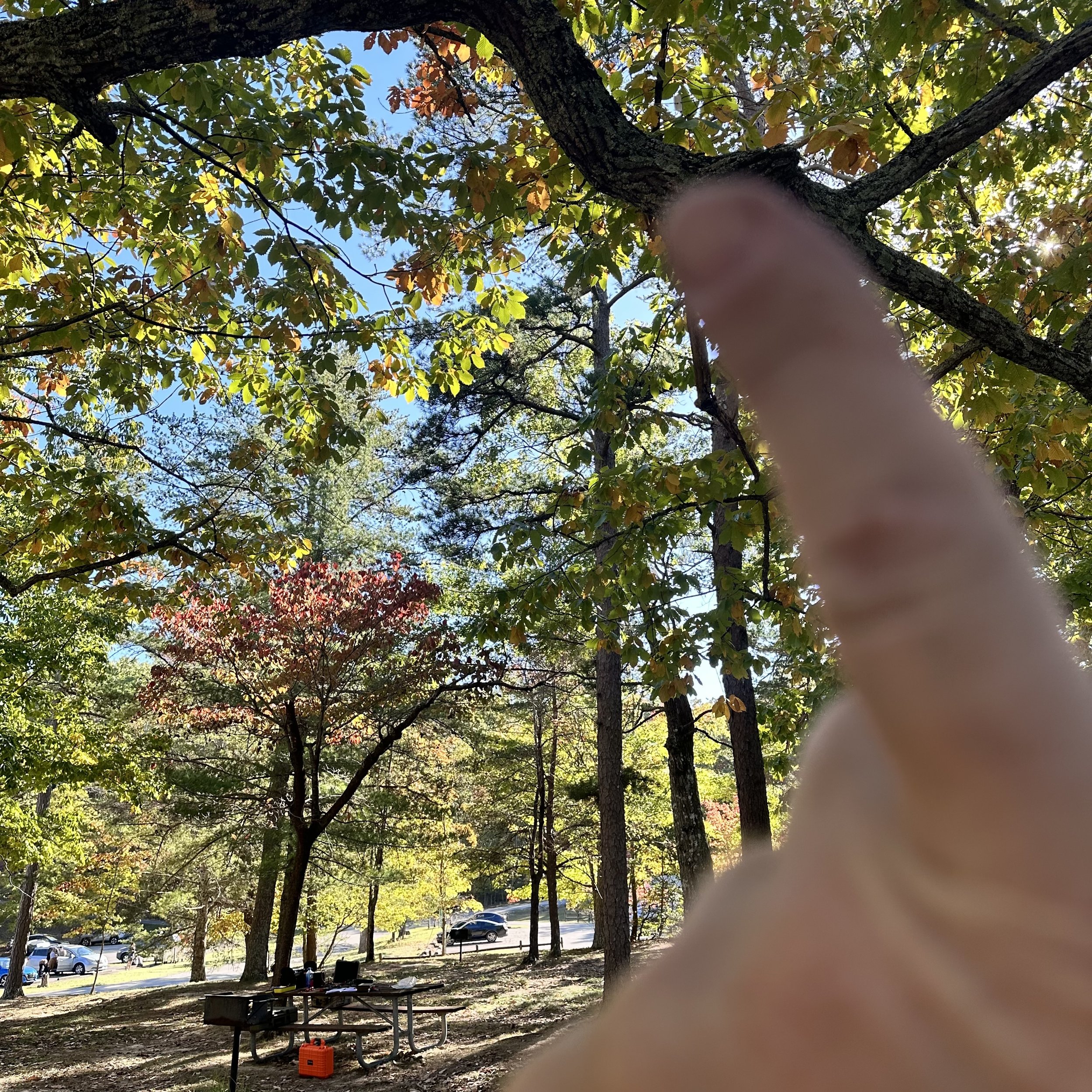
These new LiFePO3 batteries are truly amazing to me. They weigh almost nothing and I operated for two straight hours at 50 watts and the battery was still at 13.26VDC. This blows my mind. I can pick this battery up with two fingers! I also ran it through my fuse distribution block so everything was fused.


This log shows how awesome the band was on this day. I started on 10 meters CW as I was listening around and the first call I copied was England! That was when I knew it was going to be good. I didn’t get him, but shortly after I started calling CQ and 6 out of the next 10 contacts were DX!!! The first one was Chile and I am pretty sure that is the first Chilean I have ever worked.
After that I noticed the rest were from the European area of the world which is still awesome! The other domestic callsigns were still very far away and I was stoked to mess with other bands as well to see what I could hear. After these initial 10 QSOs, I found that the band was fading so I figured I had hopped on the air at just the right time and caught a wave. At this realisation, I figured I would give 17 meters a try and see what happens. It was much more difficult for some reason, not much activity at all… I guess everyone was up on 10 meters… haha.
So after that, I figured I would just test 15 meters before calling it quits for the day. Well, I must have hit a band opening on 15 meters as well. The calls started coming in and as you can see below I got South Africa! That is also a first for me!!! I normally cant hear Africa since I use less than ideal antennas. I had a blast on 15 meters and the logbook reflects that. I even worked two “regulars” that I know by name but have never met in person! KJ7DT - Paul in Idaho and K9IS (who I have written about before) - Steven in Wisconsin. Both of these men have worked me well over 50 times and I am pretty sure Paul is over 100!
It is really cool to get “Z” calls in the log though as I rarely hear this call letter on the air. I always think it is way off, and sometimes it is, like the South African station but then I get one and it next door in the Caymen Islands too…lol.

This was an awesome day and I am glad you followed along in the story with me. Until next time, I hope to work you on the air!
WK4DS - David
73
Jumping on 40 meters right quick…
Today saw me testing a theory, that 40 meters wasn’t closed just because it was late in the morning…
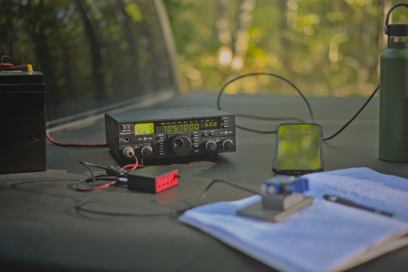
When I got to US-2169 today, I wanted to get on the air quickly, so I decided that I would activate the Sitton Gulch parking lot instead of going to the top of the mountain. This one thing adds about 40 minutes to my operating time as it takes me about 20 more minutes to drive to the top of the mountain from here and then there is the drive back down. Armed with this extra time, I decided to also add a long radial so 40 meters would tune up to a usable SWR. I was able to get the SWR on 40 meters CW down to about 1.6:1 and this is what I made all my 40 meter contacts at. The beauty of Ten Tec radios is their notoriously robust transmitters and the legend that they can survive transmitting into 10:1 SWR without ill effects. I have personally used my Argonaut 5 in 2.5:1 conditions and had no problems at all.
Today I thought I would just jump on 40 meters for a minute and see what I could scare up on CW then move over to FT8 before heading up to 20 meters. I was not ready for the pile up that happened next… It was interesting as there really wasn’t much activity on 40 meters at the time when I hopped on. It was almost lunch time at this point (late morning) and the noise on the band was picking up. I sent out my CQ a few times and it didn’t take long to get an answer. I also spotted myself on the app too and I am certain this helped immensely as well.
I worked over 10 contacts in about as many minutes and was stoked to have bagged the activation so easily. I switched over to FT8 now that I have cleared my little pileup on CW and see what I can find there!

I simply added a couple more radials to the antenna to help with SWR so that I could operate on 40 meters today. One of these radials was over 30 feet long! The 40 meter ham stick that I have is not that great of an antenna from what I have seen. The SWR is really touchy with it and I can not get it to tune without several large radials helping it. I dont know what I am doing wrong with it, but I really need to figure it out as the 40 meter band is a lot of fun!
The measurment kit below has becoume part of my permenant truck POTA kit that I take with me everywhere. It has the nanoVNA and all the associated widgets for it as well as a simple little multi-meter to check things with out in the field. This has been very valuable at times and a I recommend everyone carry a simple meter with them.

Here is a simple little hack that I found with my Ten Tec Argonaut 5 radio that I though was cool. You can make up a front (mic plug) connector for the keyer cable instead of using the tiny one on the back if you will simply wire the keyer contact from the keyer or key across the PTT contact on the mic plug. It works flawlessly and is simpler to setup for me. I have the cable for the back too should this one fail for some reason, but this is more elegant for me. Notice all the RF blocking devices I have added to the lines to reduce (read that as eliminate) erroneous characters from being sent due to stray RF.


After my little interlude on 40 meter CW, I switched radios to the sBitx to be able to work some FT8 on 40 meters as well… This was not a great idea as the SWR was 3.5:1 in the part of the band and I didn’t want to risk damage to the finals so I made one contact and then moved to 20 meters for the duration of the activation. Once on 20 meters, this is where things REALLY took off for me today. I started hunting and pouncing on contacts on FT8 before I finally just setup on an empty slot and started calling CQ myself. This produced a lot of contacts. A really good run ensued and I was glad to see that I was able to put many calls in the log on this day with the sBitx. Shoot, I even worked a couple of SSB contacts as well, but it was a struggle to be honest with only about 9 watts or so in the SSB portion since my antenna is tuned for the CW portion of the band.

Here is a rare glimpse into my “go” kit for my Ten Tec Argonaut 5 as a CW kit. I need to add the microphone to it so I can use it for SSB as well but I am not sure if the SSB mod has been done to this one yet. Haha. It works so well for CW that I have not bothered to check! But the kit contains the radio, tuner, wire antenna, key and keyer plus all the cabling to get everything connected. It is only missing a power source but that is by design. I carry batteries for remote ops or plug into the truck for mobile operations which is why I dont have a battery in the kit.


Here we have yours truly operating the sBitx on FT8 and to be honest, it works almost too well for this. To the point that I am almost not even interested in the other modes with it… Almost… I love working from the bed cover if it is nice outside as it is the perfect height for my uses.

This was a great day for radio and the logbook reflects it, looks like the solar cycle is picking up for the winter run! This is the time to get on ten meters and work some DX yall! I should know as the next blog post will reveal next week!
73
David


sBitx V3 HF radio special functions
I recently activated a couple of parks and decided to add a bluetooth keyboard to the sBitx V3 and see how operational it would be like that.
On this day I decide to activate Chickamauga Battlefield but first it seems a “widow maker” dead tree fell into the pull off at US-0716… I cleared what I could without a chainsaw and then setup the radio.
The below view gives you a good measure of just how big this “parking lot” is…lol. This lot would hold two small cars or my truck and a motorcycle and that is about it. The cars going by are the worst part though. These cars sometimes emit terrible amounts of RF hash… first world problems I guess…
I setup the usual antenna system but only for 15 meters as I was feeling a bit adventurous today and figured I would stick it out on 15 meters till I got the activation secured. I could have done the same thing in 15 minutes on 20 meters using CW, but there are plenty of ops on 20 meters already so I figured I would warm up another band instead. Well, the QSB was obvious when watching the FT8 waterfall, you could see the band come in and out as the stations would get real loud then fade almost all the way out. This made FT8 challenging since it takes a couple of minutes to complete the series of messages. None the less, I was able to get 11 contacts anyway, even with the frustration of some more that never did complete… but so is HF, she is a fickle girl at times…
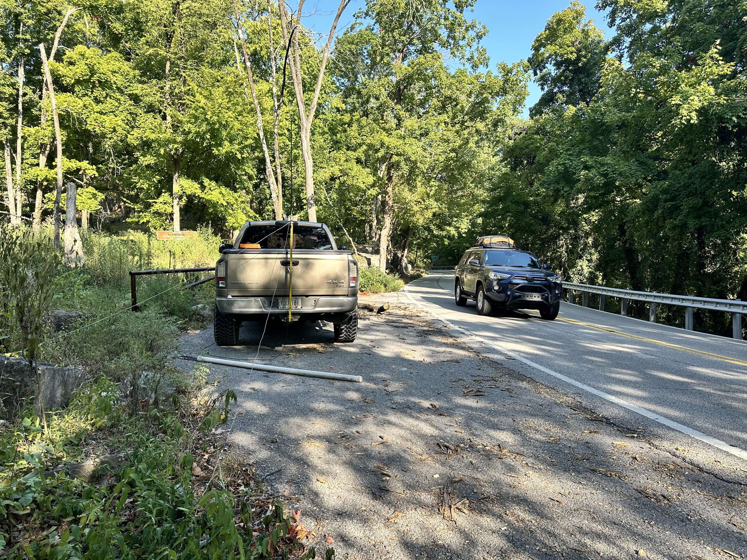

Today saw the common mode choke come back as I had it nearby and the SWR was a little off. So I threw it inline with the radio to keep it happy. These are really simple to make and I show how I do it on a video, that is in live-stream format, on YouTube, at this link if your interested. Link to video about making a common mode choke for QRP work (it can probably handle 100 watts without issue but I have not tried it) and POTA ops.
Below we have the operating position for today, notice I didnt even bother with the CW key today as I had planned from the outset to only work FT8 and then pack up. Took me longer than I had anticipated but I did it! haha. Well, to be fair, I did have a CW key in this photo, you see the sBitx will also send CW from the keyboard. I use this to great effect at the other activation I am going to talk about shortly…
The one thing I really like about using 15 meters from a park with a ham-stick antenna is that I am able to work DX pretty consistently. As we see here I worked 5 DX stations out of the 11 I got into the logbook that day. That is a phenomenal amount of DX stations for me. I just seem to get REALLY good propagation when I get on 15 meters for some reason. I will get one every now and then on 20 meters, but I get them regularly on 15… just something to think about if you are into chasing DX and want to also do POTA…and use a ham-stick antenna. You see every contact you make from the park counts towards your POTA log, so even if they are not participating in the program, like a recent ragchew I had while at a park, still counts to your 10 you need for that day.


The other park I went to recently was Booker T Washington just NE of Chattanooga TN. I have not been back to the park for a while so it was nice to put it in the log again. Instead of struggling around on 15 meters at this location I chose to run 40 meters and 20 meters for a while instead. I hopped on 40 meters FT8 to start with as I have not been on that band from a park using FT8 yet. It did not disappoint. There were a few stations still lingering on the air so I was able to work several of these stations before the band noise got so bad that I could not complete contacts and further. I even worked the W0E special event station which is really cool.

This is a really old park and has changed over the years. These were once campsite areas but have since been simply turned into day use “picnic” areas with most of them essentially becoming simply parking spaces for people that go for walks. There are a few that have picnic tables and even grills but most are now just parking spaces along the loop.

After working 40 meters FT8 for about 1/2 hour or so, I decided to give keyboard CW a try on the sBitx V3. This also did not disappoint. I was surprised how easy it was to transition from using a paddle to using the keyboard to send CW. It did take a little getting used to for me to become proficient with it, but after just a few minutes it was like I had been doing it for years and I even figured out the keyboard short cuts for the memories too, so I could use them easily for the exchange and such. This made it easy to log as well as send so I kinda liked using it this way to be honest. It is more fun to me to use a keying device of some sort, but if I forget my key, I now know I can still get on CW and make POTA contacts with it easily. That is a nice option to have in a 400$ radio to be honest about it. Well, to be fair, if you have used an sBitx for sending CW, then you also know how frustrating the keying is with it. It is possible to use it to about 20 WPM or so without much issue but above that, the keying delay because of the way the code is written, will cause the radio to send mistakes. Once you learn to hold the key just a little longer than usual it works just fine at speed of 20 WPM and less so it isnt a huge deal for me. Much over that though and the radio just wont work as of right now. From what I have heard, there is a beta of the next version of the code that will address this problem, but I am not able to compile the code properly so I am patiently waiting for the official release to drop before upgrading again. JJ just released an update to his fork of the code as well and it has a bunch of new features like a tune button and such, but I am also waiting on that one as well so that the bugs get ironed out before I install it on my machine. Now back to the activation…
After that I hopped on 20 meters FT8 and jumped into the fray for a few minutes to see if I could grab a few more calls for the day right quick and that would be a yes! I got 3 more stations in the log using this mode on 20 meters as well. What a day!

Today also saw nice enough weather to setup on the bed cover and these two photos show how I have to do this if I am on the truck power cable from the cab. It is just long enough to reach out the window and power the radio…lol. Barely… (I really should make a longer power cable or something…haha) This worked out today as the whole location was in the shade so I didn’t have to fight off the sun while trying to activate. A lot of the time, this is the reason I don’t operate from the bed cover in the summer, it is in the sun and just plain hot…
As you can see below, the height is about right for me activating too, I can write as well as operate the radio and it is at just the right height for me and my stature. If you like to work POTA, and you do regularly activate, what is your normal operating position? I have a few with this one being one of my favorites even though I don’t use it much.


Thank you for following along and I hope to work you on the air soon!
73 - WK4DS