WK4DS Amateur Radio Blog
Search Posts
Alafia River POTA: How 12 Meters Delivered 72% DX While Everyone Else Fought on 20m
Everyone defaults to 20 meters for POTA. It's crowded, competitive, and honestly…boring at this point. So at Alafia River State Park (US-1829), I did something different: I skipped 20 meters entirely and focused on 12 and 15 meters instead. The result? A 72% DX rate on 12 meters, contacts to 10 different countries in under an hour, and some of the best propagation I've experienced from a Florida state park. All at 10 watts.
Everyone defaults to 20 meters for POTA. It's crowded, competitive, and honestly…boring at this point. So at Alafia River State Park (US-1829), I did something different: I skipped 20 meters entirely and focused on 12 and 15 meters instead. The result? A 72% DX rate on 12 meters, contacts to 10 different countries in under an hour, and some of the best propagation I've experienced from a Florida state park. All at 10 watts.
Let me show you why 12 meters is the band everyone's ignoring while they pile up on 20m.
Why I Skipped 20 Meters Entirely
Look, I get it. 20 meters is the default POTA band. It's where everyone goes, it's where the hunters expect you to be, and it's reliable. But reliable also means crowded, and crowded means QRM, pile-ups, and fighting for frequency space with a dozen other activators doing the same thing.
We're near solar cycle maximum right now, which means the higher bands (10m, 12m, and 15m) are performing like 20m used to during previous cycles. But most POTA activators haven't adapted their band strategy yet. They're still automatically going to 14.061 MHz CW or 20m SSB without even checking what's happening higher up in frequency.
So today at Alafia River State Park with Chas (who was also activating), I made a conscious decision: skip 20 meters completely. Start with 12 meters, see what happens, then move to 15 meters. If those bands produced nothing, I could always drop to 20m as a backup. But I had a feeling 12m was going to surprise me.
Spoiler: it absolutely did.
The Alafia River State Park Setup
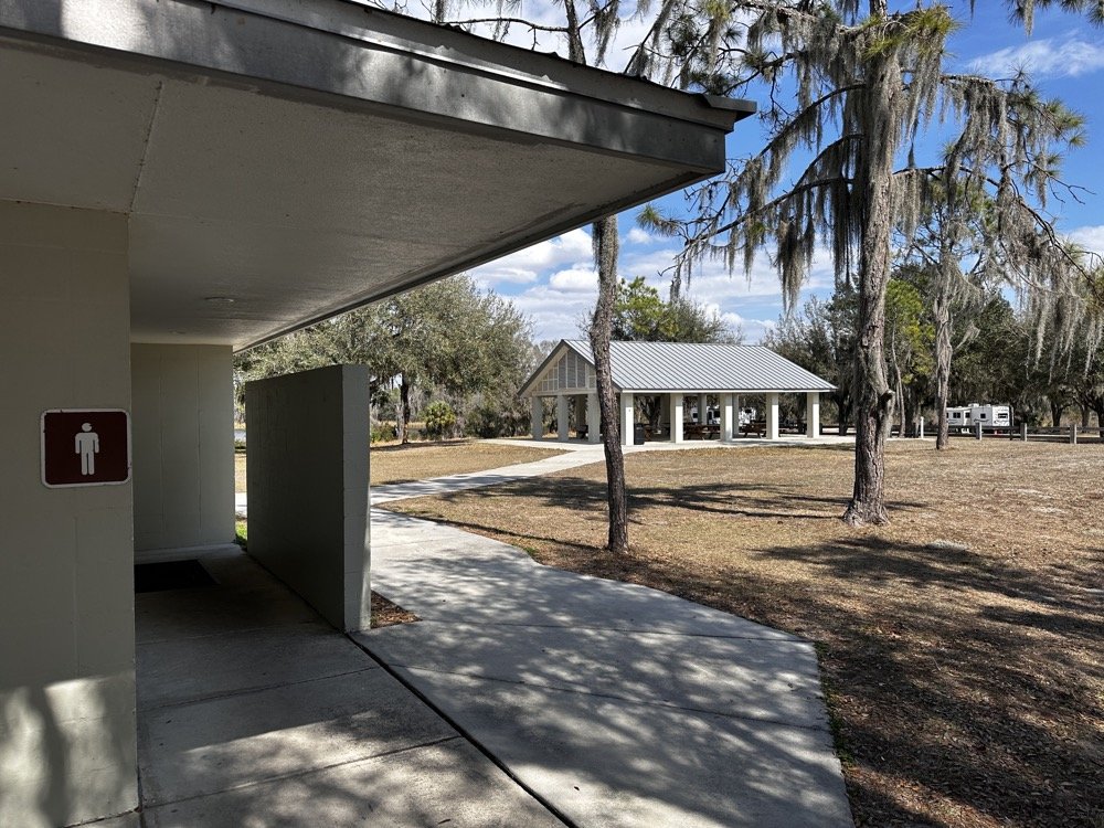
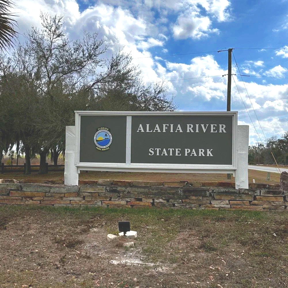
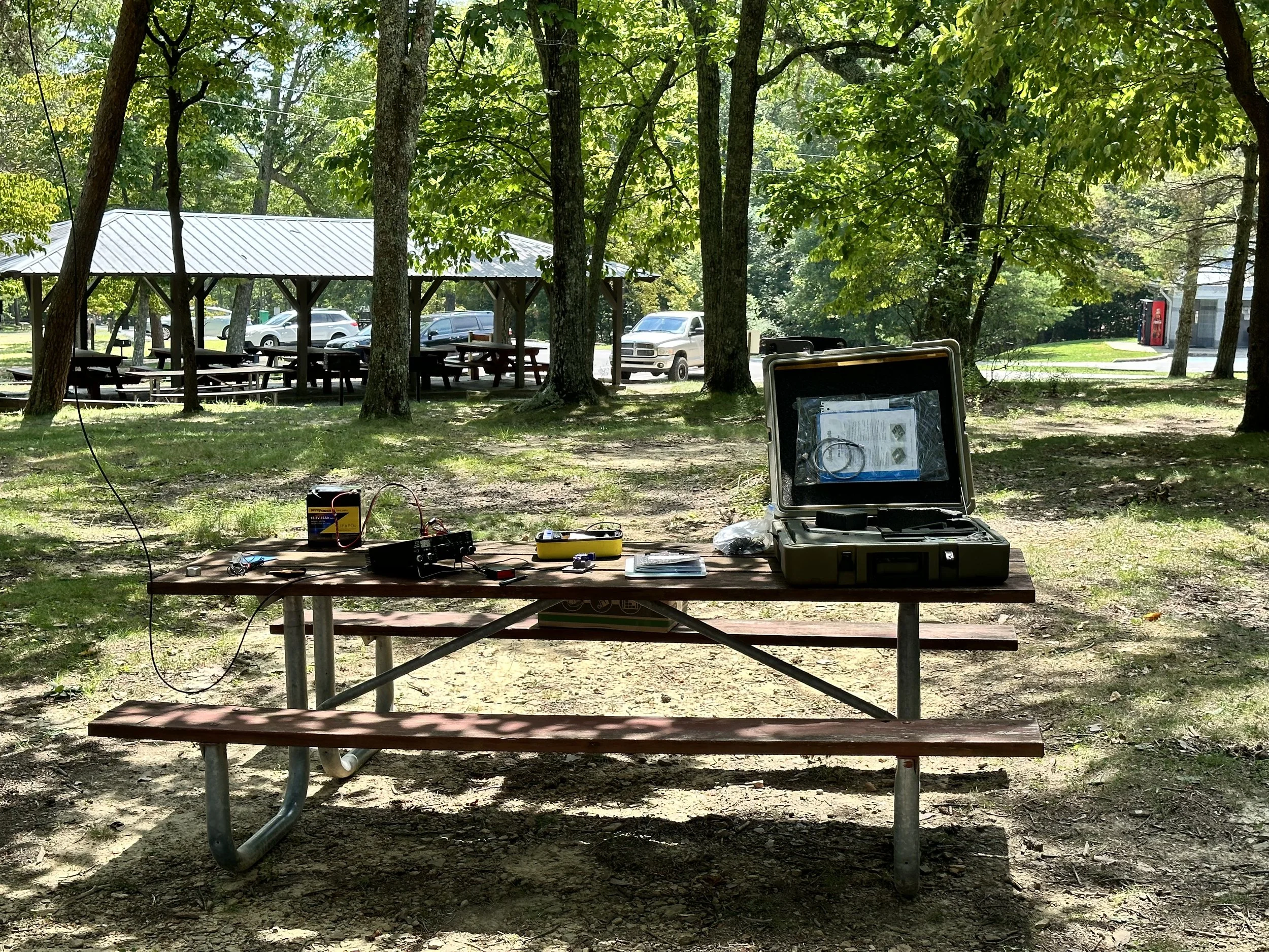
Alafia River State Park is designated US-1829 for POTA and it's located in Lithia, Florida, just southeast of Tampa. The park has a really nice covered pavilion with picnic tables, bathrooms, and RV camping area with good tree coverage. Spanish moss everywhere, typical Florida scrub vegetation, and plenty of tall trees for wire antennas.
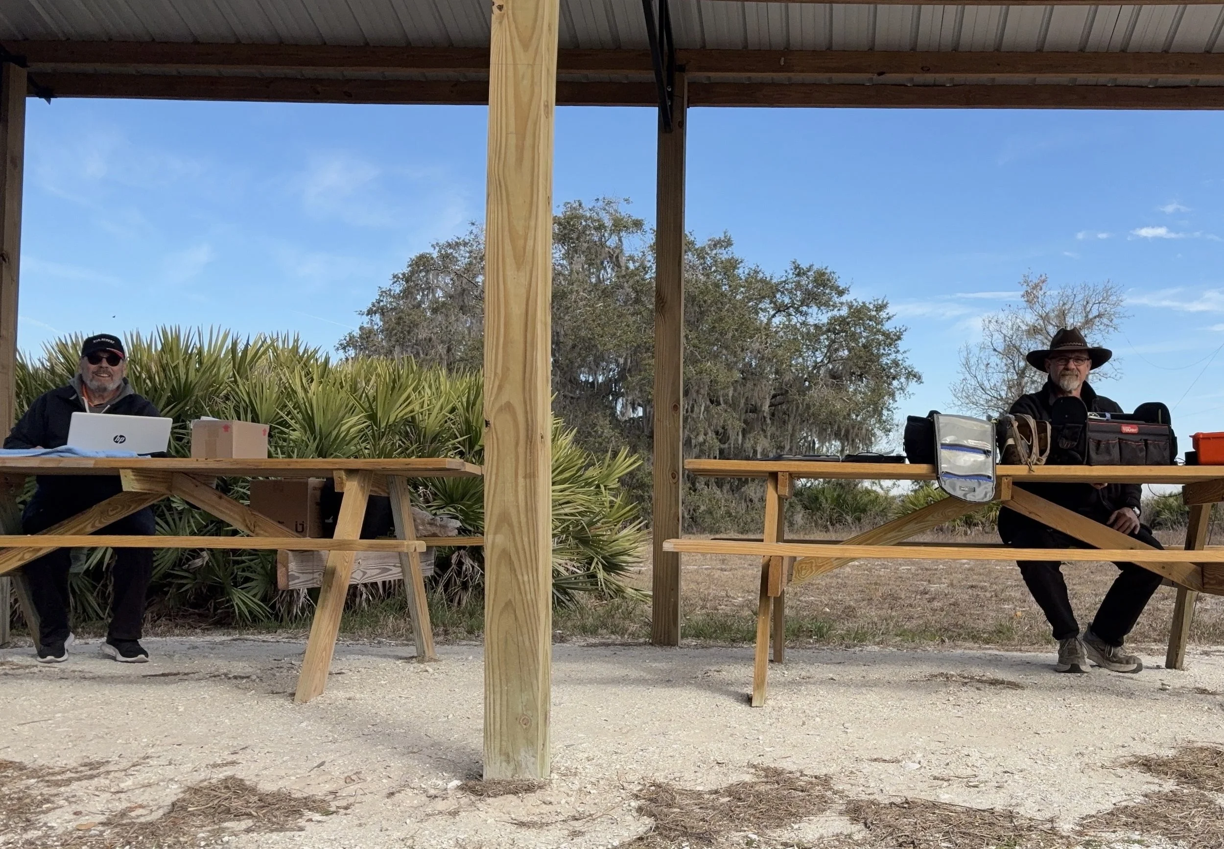
The covered pavilion where we set up for the activation. Clean facilities, picnic tables, and good tree coverage for wire antennas.
Chas and I both set up under the pavilion, him at one table, me at another about 20 feet away. This gave us enough separation to avoid too much RF interference between our stations, though we still had to coordinate who was transmitting when to avoid stepping on each other.
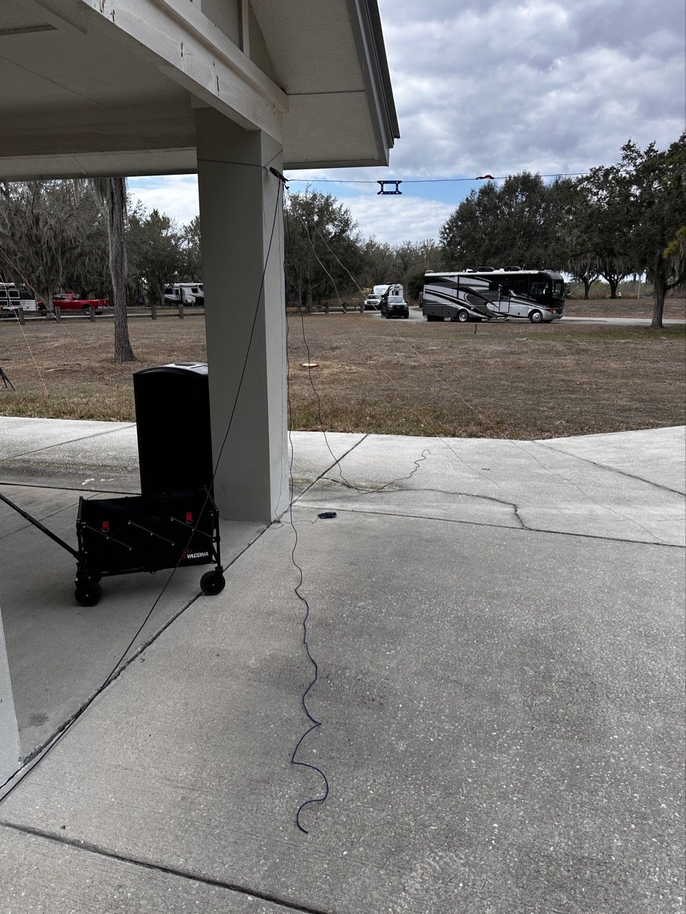
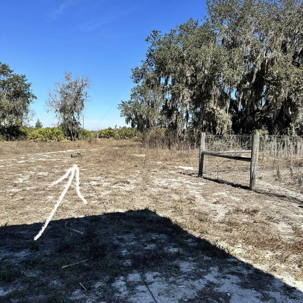
My antenna setup was a 65 foot random wire thrown up into one of the larger trees near the pavilion. I'm guessing it got maybe 30-35 feet up into the branches, which isn't spectacular but it's what I could reach with the available trees. The radiator came down to the tuner that is tied up high on the corner column of the pavilion. I also used a larger set of radials so the antenna would be more likely to work on 40 meters. But that didn’t seem to matter as I would come to find out…
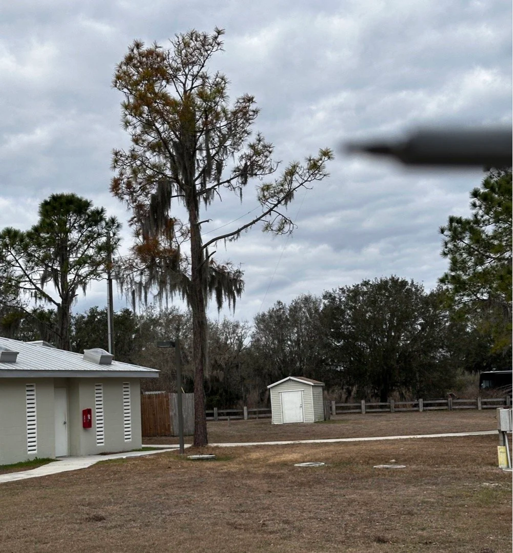
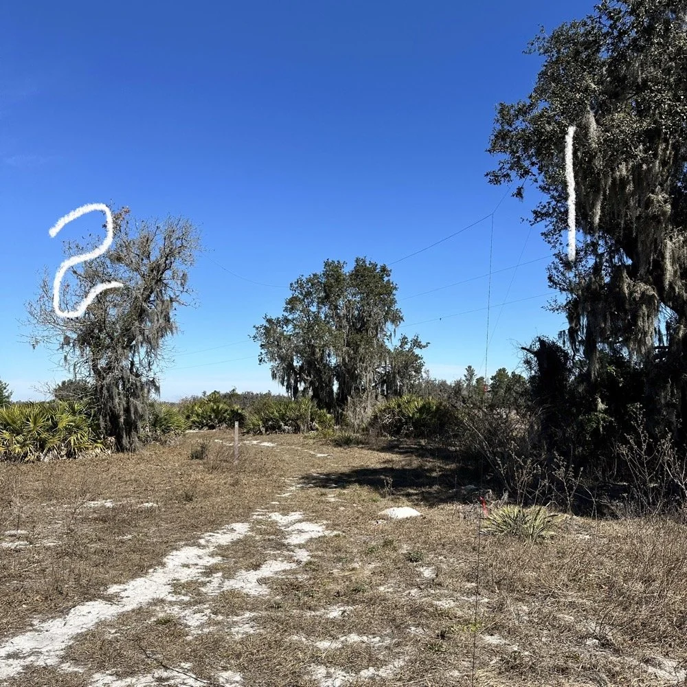
This is the tree branch I had my wire antenna ran out to, if you look close, you can see the wire antenna in the photo.
Now here's where I need to be honest about the equipment struggles today... I am not immune to making common, simple mistakes and here are a couple from today that I actually did. I started out on 40 meters and wanted to work some stations there since it was supposed to be about 9:30 when I would be starting the activation. Well, that isnt how it went at all. I started out usng the Elecraft T1 antenna tuner with the sBitx. This turns out to be a problem though, you see JJ and the team added a high SWR protection script in the new code and if the SWR goes over 3 to 1 then it automatically turns the output power all the way down to prevent it from killing the finals. Well, it seems that as the Elecraft T1 goes through the tune process, the SWR will rise above 3:1 and this shuts off the RF from the radio and the tuner cant finish the tune…
Elecraft T1 Antenna Tuner with wire antenna and ground radials tied to pavilion column.
But before I figured this out, there is another small detail… The sbitx tune feature is simple, hit a button and it will “dead key” the radio and hold that for a time. Both the level of power and the time are adjustable in the menu so I set it to 20 seconds and the level to about 5 watts as the T1 is a QRP tuner. The Elecraft T1 can tune about anything you want to use for an antenna to a usable SWR so I was confident in the little tuner. Soooo, I would hit the tune button on the sBitx then sprint over to the tuner and hit the button on it to activate the tune feature on the tuner. The tune timer on the sBitx would finish right as I would get back to the radio. I would check it with a Morse code key in CW mode and the radio would and SWR of 5 or 6 to 1 and the output power would be turned all the way down… I would turn the power back up to 5 watts and then try again. I performed this comedy act a few more times before seeing the “SPLIT” button was on and that the B VFO was on 15 meters!
Armed with this knowledge, I confidently turned off split and immediately found myself back to the HIGH SWR alarm on the sBitx… No matter what I did, as soon as the Elecraft T1 would start the tune cycle, it would trip the radio SWR protection feature and this would turn off the transmitter in the radio and by extension, also shut down the tuner mid-tune… Frustrated by this revelation, I found myself getting the Penntek TR-35 out of the bag and using it a couple of times to find out it was doing the same thing! After spending 30 minutes doing this, I finally threw in the towel and just went out to the truck and got my MFJ941 manual tuner and the nanoVNA and connected it in place of the Elecraft unit.
But the fun doesn’t stop here! I could not get this one to tune either! What was going on here!!! Well, it turns out that I had at some point switched the MFJ’s antenna selector from wire to the next antenna port and didn’t check it so I was effectively tuning the SO239 connector on the back of the tuner to 40 meters!!! Good grief, this has been a mess! Once I figured this out and set the tuner to the correct antenna, it tuned up almost instantly. This whole debacle took over an hour to sort out, so if you think you are not very good at POTA setup and breakdown because you see these “old pros” doing it effortlessly, just know we are not immune to errors and odd problems either…haha.
Back to the rest of the activation report…
Radio-wise, I was running the sBitx v3 at 10 watts maximum. For those not familiar with QRP POTA operations, 10 watts is pretty normal power level, it is about 1/10th of what most people run. But it's what the sBitx puts out reliably on all bands and that is well within the Elecraft T1 tuner’s power handling capability (remember, I had started with this tuner), and honestly, with propagation conditions this good, power isn't the limiting factor anyway.
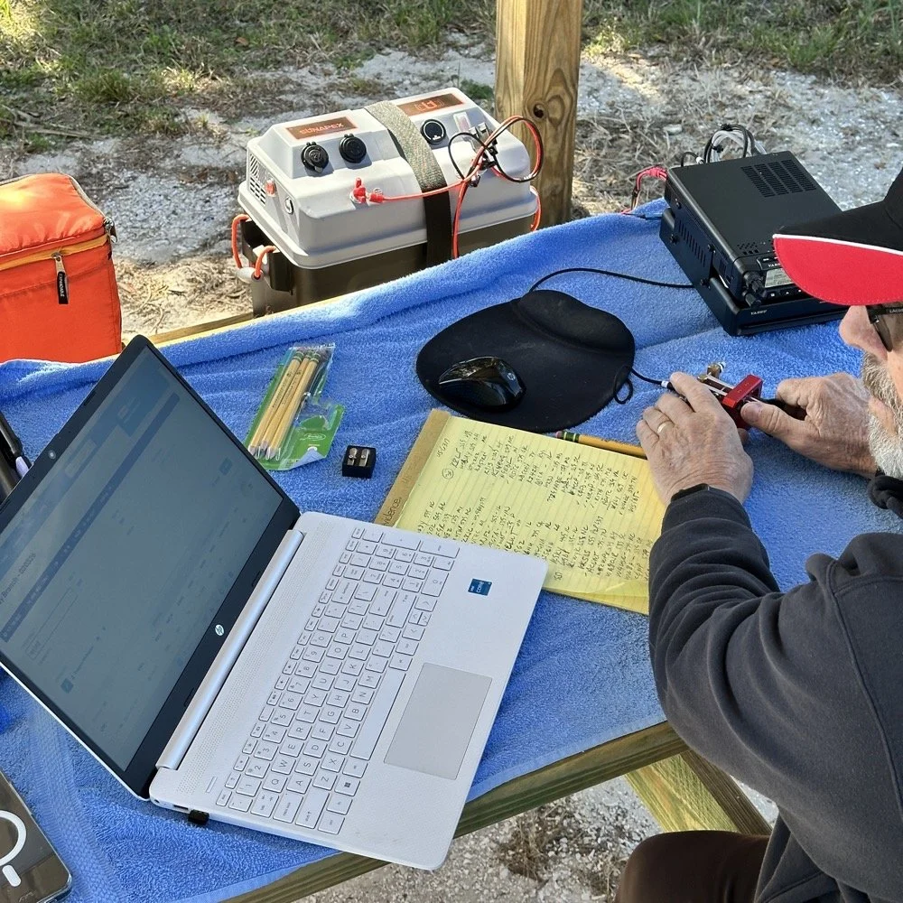
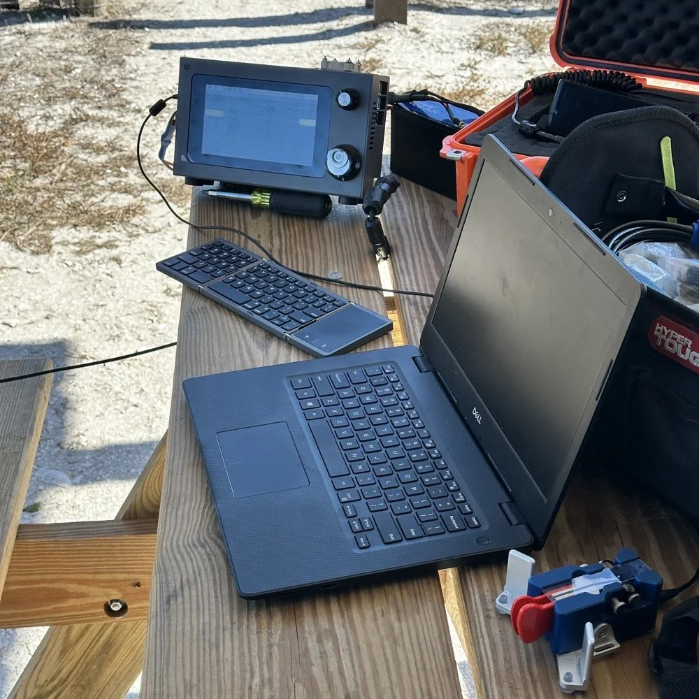
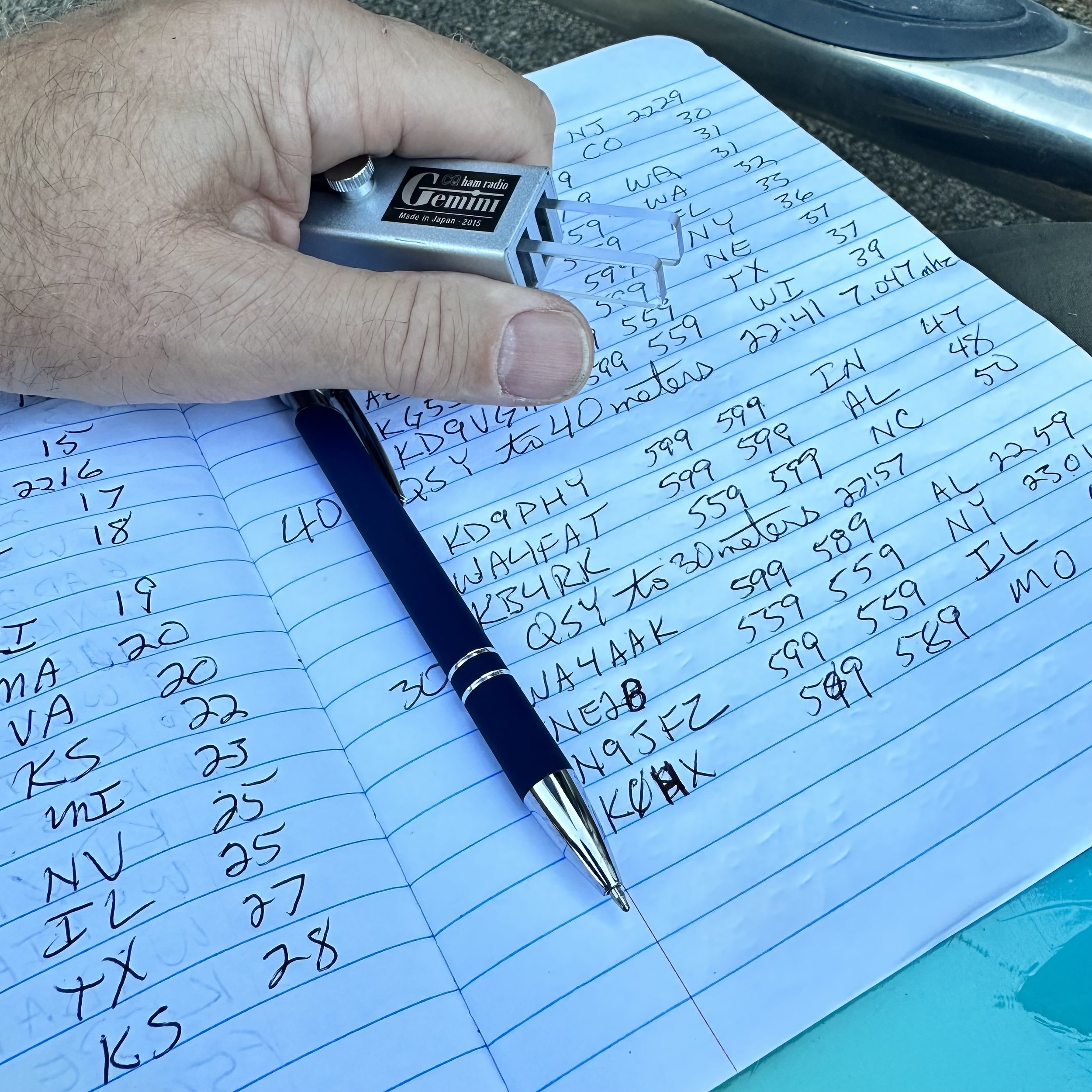
I had my Dell laptop for logging contacts in HAMRS (the POTA logging software), a foldable keyboard because typing on a laptop in bright sunlight is annoying, a CW paddle, and the usual field gear—water bottle, clipboard with paper log backup, etc. Pretty standard POTA kit.
12 Meters: The Band Everyone's Ignoring
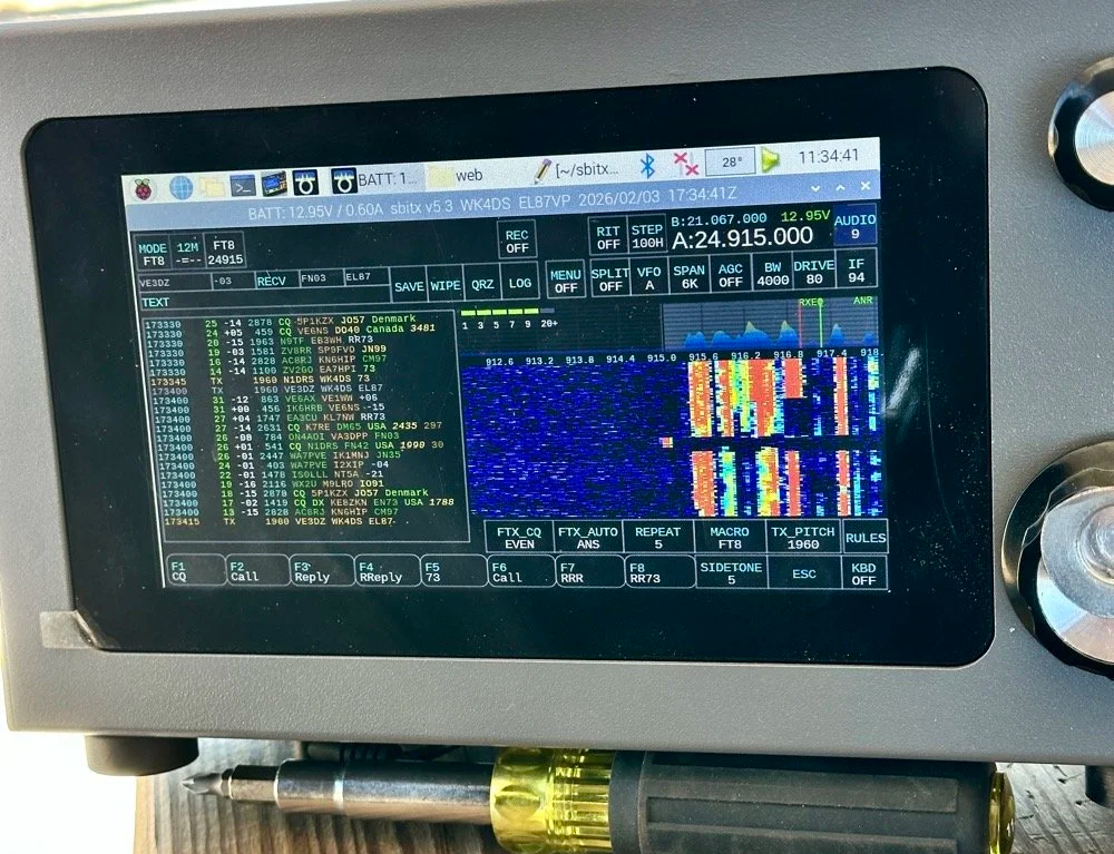
I fired up the sBitx on 12 meters around 1600 UTC (11:00 AM local time) and started calling CQ on FT8 at 24.915 MHz. Within seconds, I was getting responses. And not just USA stations, I'm talking Greece, France, Netherlands, Spain.
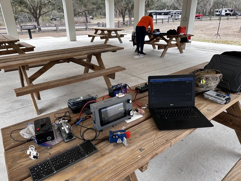
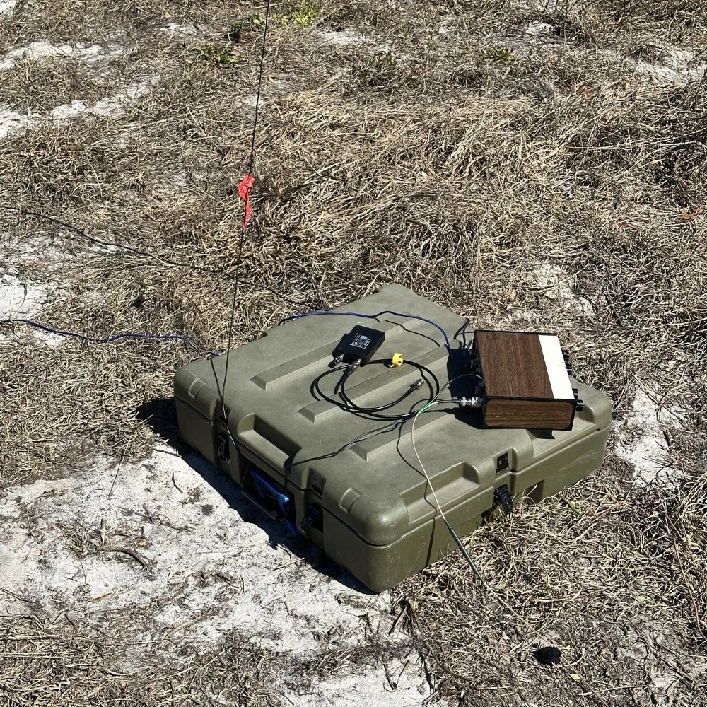
The station: sBitx v3 running 10 watts, MFJ-941 manual antenna tuner, Dell laptop for logging, Begali Traveler CW paddle, and field keyboard. This setup delivered 72% DX on 12 meters today!!!
The first contact was PB2A in the Netherlands at 1620 UTC. Signal report was strong both directions. Okay, that's promising! 12m is open to Europe!
Next contact: EA5KB in Spain at 1622 UTC. Also solid copy.
Then SV1GYN in Greece at 1626 UTC, followed by SV8EFJ (also Greece) at 1631 UTC.
This is when I realized 12 meters wasn't just "open" to Europe it was absolutely on fire! In the next hour, I worked:
Three stations in Greece (SV1GYN, SV8EFJ, SV7FDA)
Two stations in France (F4IFO, F6BIA)
Spain (EA5KB)
Netherlands (PB2A)
Portugal (CT1FIU)
Czech Republic (OK1DTC)
Poland (SP2GCJ)
Plus Brazil, Dominican Republic, and Canada as bonus DX
That's 10 different countries in less than an hour on 12 meters. With 10 watts. From Florida. To put this in perspective: of the 18 contacts I made on 12m, 13 were DX (non-USA). That's a 72% DX rate.
When was the last time you heard anyone report a 72% DX rate from a POTA activation? This is why solar cycle maximum matters, and this is why you should check 12 meters before defaulting to 20m.
The propagation held solid from about 1606 UTC until around 1657 UTC when it started to fade. That's nearly an hour of wide-open conditions to Europe from a Florida state park with a wire antenna and 10 watts. Just... chef's kiss (I saw someone else use this term and it absolutely applies here, lol). This is what amateur radio is supposed to be.
15 Meters: The Reality Check
After 12 meters started fading around 1700 UTC, I switched to 15 meters to see if the party was still going. Spoiler: it was not.
15 meters wasn't dead as I made 10 contacts between 1738 and 1748 UTC but the DX had evaporated. Out of those 10 contacts:
8 were USA stations (domestic)
2 were Germany (the only DX and were way down in the noise)
That's a 20% DX rate on 15m compared to 72% on 12m. The contrast was striking and immediate. As soon as I moved from 24 MHz to 21 MHz, I went from European pile-ups to mostly USA stations.
This isn't a knock on 15 meters, it's just propagation and we all know how the sky likes to mess with out brains…. By late afternoon (1730-1800 UTC), 15m was transitioning from long-skip DX to shorter-distance USA contacts. Which is fine if you need domestic QSOs to reach your 10-contact activation threshold, but if you're chasing DX, 12m was clearly the better choice earlier in the day.
The lesson here: timing matters just as much as band selection. 12m was the star of the show from 1600-1700 UTC. 15m was better for domestic contacts after 1730 UTC. If I'd started on 15m at 1600, I probably would've missed the entire European opening on 12m.
The 40m and 10m Bookends
I also made a few contacts on 40 meters and 10 meters to round out the activation, mostly just to see what those bands were doing.
40 meters (4 contacts): Mostly short-skip USA stations. Nothing surprising here as 40m in the afternoon is for regional contacts. It works, it's reliable, but it's not going to give you Greece with 10 watts and a random wire thrown over a tree branch.
10 meters (4 contacts): Had a brief opening but nothing like 12m. A couple of USA stations and some Caribbean/Central America. 10m can be spectacular during solar max, but today it was just "okay." You could just watch the stations fade in and out on the band here on the waterfall…
Final tally for the activation:
Total: 36 QSOs
12m: 18 QSOs (50% of total) - 72% DX rate
15m: 10 QSOs (28% of total) - 20% DX rate
40m: 4 QSOs (11%)
10m: 4 QSOs (11%)
Modes: 50% CW, 50% FT8
Twelve meters did half the work and delivered nearly all the DX. That's the story.
Operating With Chas: Multi-Operator Coordination
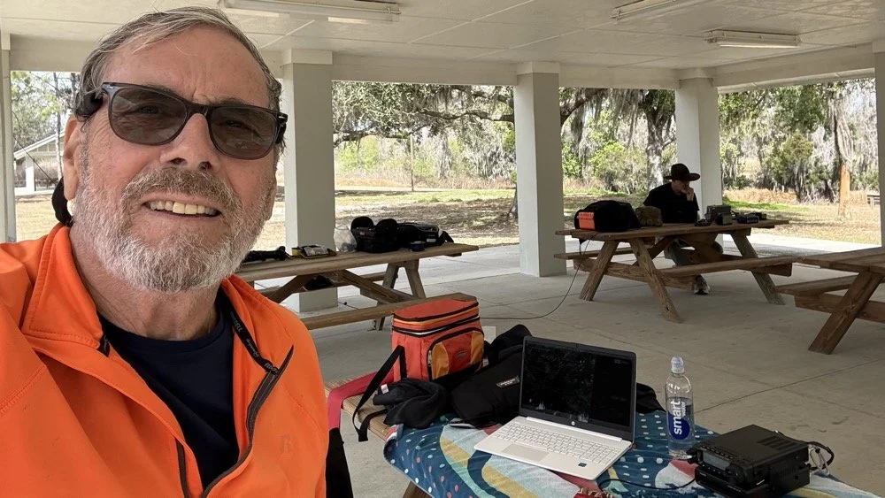
Chas (NA2B) at his operating position with me in the background. Multi-operator POTA setup at Alafia River State Park—he's about 20 feet away to minimize RF interference.
Chas was set up about 20 feet away at another picnic table under the same pavilion, also activating US-1829. We coordinated our operating so we weren't transmitting on top of each other. He started on 30 meters since I was on 40 and after I finished on 40, I jumped all the way to 12 meters so he could move slowly up the band through 20 then 17 and even 15 before he got his 60 and called it a day. He runs 50 watts currently and has great success with it, but the QRP bug has bitten him and he is going to be turning down the power dial soon… or so he says… haha
This coordination is important for multi-operator POTA setups. You can absolutely operate two stations simultaneously from the same park, but you need enough physical separation to avoid RF interference (20-30 feet minimum), and you need to pay attention to who's transmitting when. If both operators key up at the same time on different bands, you'll hear it immediately as front-end overload or mixing products.
It actually works out pretty well though, you have someone to talk to between contacts, you can share band information ("hey, 12m is wide open to Europe right now"), and if one operator needs help with something technical, the other person is right there. Plus it makes the drive more enjoyable when you're carpooling to the activation site (which we didn’t do this time, but this point is still valid). All of this and it is just plain fun to hand out with a like minded person for a while and just have the fellowship.
Chas and I have done several multi-op activations now and we've got the coordination pretty well figured out. As long as you're mindful of the RF environment and don't step on each other's transmissions, it's actually a really fun way to do POTA.
Lessons for Other POTA Activators
If you take away one thing from this activation, let it be this: check 12 meters before you default to 20 meters.
Most POTA guides and YouTube videos focus on 20m and 40m because those bands are "reliable." And they are! You can almost always make contacts on 20m or 40m during a POTA activation. But reliable isn't the same as optimal…or fun..
We're at solar cycle maximum right now (or very close to it), which means the higher bands—10m, 12m, and 15m—are performing better than they have in a decade. But those bands are only open during certain times of day, and you have to actually check them to know.
Here's my recommended POTA band strategy for 2025-2026:
1. Start with 12 meters during daylight hours (1500-1900 UTC / 10 AM - 2 PM local) Check FT8 on 24.915 MHz or CW around 24.900-24.910 MHz. If you see European or South American stations, stay there. Don't move until the band fades.
2. If 12m is dead, try 15 meters next Same time window. 15m opens a bit earlier and stays open a bit later than 12m.
3. If both higher bands are quiet, then drop to 20 or 17 meters You haven't lost anything by checking 12m and 15m first, it only takes 5 minutes to scan FT8 and see if there's activity. But if you skip straight to 20m, you might miss the entire European opening on 12m.
4. Add 40 meters in the evening or early morning 40m is your regional workhorse. Use it to fill in USA contacts if you need to reach your 10-QSO activation threshold.
5. Keep an eye on 10 meters during solar max 10m can be absolutely bonkers during cycle peaks. Sometimes it's dead, sometimes it's a highway to Japan. Worth checking.
Key point: Solar cycle conditions change everything. The band strategy that worked in 2019 (solar minimum) doesn't apply in 2025 (solar maximum). Adapt your approach, check the higher bands first, and you'll be rewarded with DX that most POTA activators never experience because they're stuck in the 20m/40m routine.
The "Skip 20m" Strategy: Does It Always Work?
Okay, let's be realistic here. Will 12 meters always deliver 72% DX rates? No, of course not. Propagation is fickle, solar conditions vary day to day, and sometimes the higher bands are just dead. The sun giveth and the sun taketh away.. lol.
But here's the thing: you don't know until you check. And checking takes 5 minutes to tune to 24.915 MHz on FT8, watch the waterfall for 1 minute, and see if you're decoding any DX stations. If it is a yes, start calling. If no, move down to 20m like you were going to do anyway.
The worst-case scenario is that you "waste" 5 minutes checking a dead band and then go to 20m as your backup. The best case scenario is that you find a wide open band to Europe with zero QRM and work 10 countries in an hour with 10 watts.
I'll take that bet every time.
Also worth noting: 12 meters is way less crowded than 20m. On 20 meters during a weekend, you're competing with dozens of other POTA activators, contest stations, and regular QSOs. On 12 meters? Most of the band is empty. You can call CQ on an open frequency without worrying about stepping on someone else, and when DX stations hear you, you're often the only POTA station they can work on that band.
Less QRM, better propagation, higher DX percentage, what's not to love?
Alafia River State Park: Worth Activating?
As for US-1829 specifically: yeah, it's a nice park. The covered pavilion makes POTA operations comfortable even in Florida weather (sun, rain, whatever), the facilities are clean and modern, there's RV camping if you want to stay overnight, and the trees provide decent antenna support.
It's about 30 minutes southeast of Tampa, so it's accessible if you're in the area. Not a destination park like some of the big state parks, but definitely worth activating if you're looking for a Florida POTA location that isn't mobbed with tourists.
The tree I used for the 65-foot random wire was a large pine tree of some variety with good height and thick branches for support. Spanish moss everywhere, typical Florida landscape. Got the wire up to maybe 30-35 feet, which is serviceable if not spectacular.
One note: there were RVs parked in the camping area about 100 feet from the pavilion, so we weren't completely isolated. Nobody bothered us though, and one RV owner came over to chat about amateur radio for a few minutes. Friendly folks just out camping.
Best time to activate: Late morning to early afternoon (local time) if you want to catch the 12m European opening. Earlier in the day if you want 40m to be productive for longer distance USA contacts.
Facilities: Bathrooms, covered pavilion with tables, RV camping, paved parking. Bring your own food/water.
Antenna options: Plenty of trees for wire antennas. A vertical would work too if you prefer.
Final Stats and Conclusion
Let's wrap this up with the numbers:
Total QSOs: 36
12 meters: 18 QSOs (50% of total) - 72% DX rate
15 meters: 10 QSOs (28%) - 20% DX rate
40 meters: 4 QSOs (11%)
10 meters: 4 QSOs (11%)
DX Worked: 12 different countries
Greece (3 QSOs)
France (2)
Germany (2)
Brazil (2)
Plus Spain, Netherlands, Portugal, Czech Republic, Poland, Canada, Dominican Republic, US Virgin Islands
Modes: 50% CW, 50% FT8 Power: 10 watts QRP Antenna: 65-foot random wire at about 30-35 feet
The takeaway: 12 meters is the secret weapon for POTA DX during solar cycle maximum. While everyone else is fighting on 20 meters, you can have an entire band nearly to yourself with better propagation, less QRM, and DX rates that would make any contester jealous.
So next time you're setting up for a POTA activation, do me a favor: check 12 meters first. You might be surprised what you find.
Thanks and get your radio out!
Have you worked DX on 12 meters during POTA activations? What bands are you checking during solar max? Drop a comment! I'd love to hear what's working for you.
You can help support this website by using these Amazon Affiliate Links:
QRP/Portable Radios:
Antennas & Tuning:
CW Equipment:
Power & Accessories:
Organization & Transport:
BONUS ITEMS
73, David / WK4DS
Joint POTA Activation with NA2B at Moody Branch: 104 CW Contacts in 4 Hours
Today I went to a POTA park to meet up with Chas NA2B, another amateur radio operator that lives just down the road from Chito Branch nature Reserve where I have been spending a lot of time here lately. He saw I was at the park on the spot page and simply hopped in the car and drove over for an eyeball QSO and to see if I wanted to meet up with him at some point and setup for an activation.
Today I had the pleasure of meeting Chas NA2B for our first joint POTA activation at Moody Branch Wildlife Management Area (US-6317) in Florida. What started as a chance encounter on the POTA spot page turned into a memorable 4-hour operating session that netted 104 total CW contacts between our two stations.
Today I went to a POTA park to meet up with Chas NA2B, another amateur radio operator that lives just down the road from Chito Branch nature Reserve where I have been spending a lot of time here lately. He saw I was at the park on the spot page and simply hopped in the car and drove over for an eyeball QSO and to see if I wanted to meet up with him at some point and setup for an activation.
This blog post will be an amalgamation of both discussing the activation as well as my new friend.
Planning the Activation
We communicated a good bit over the past week via text to line up a good day, (turns out every day is a good day for Chas…haha) and chose Tuesday as I had some business to attend to on Wednesday and the weather was way warmer than the previous day. The weather actually turned out to be about perfect to be honest about it. We agreed on Moody Branch US-6317 and 9:30 as the start time. We had planned to operate till about 2 if things were going good so on the day of, I load up the truck and head out. It takes about an hour to get there from where i was staying so I stopped and grabbed coffee and snacks along the way. Who doesn’t want a caffeinated CW op on the other end of their QSO???
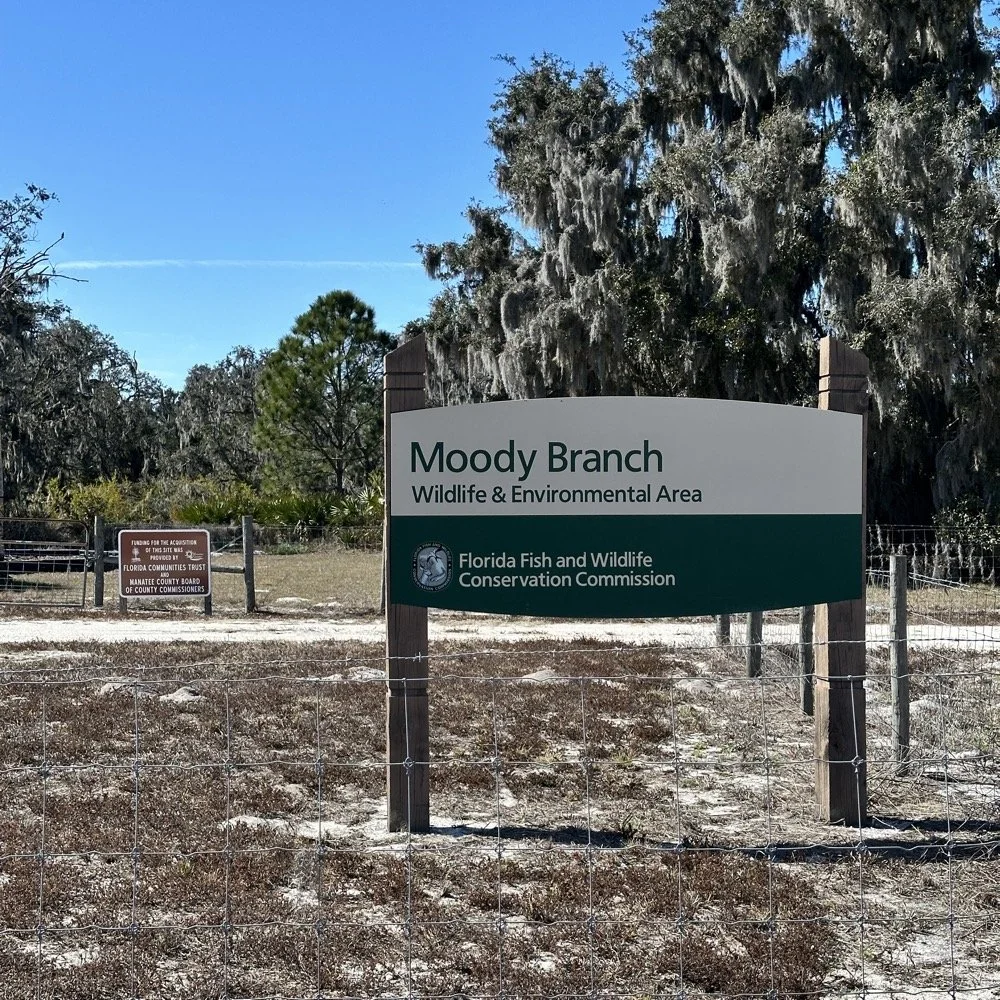
When I get there I am greeted with the standard issue Florida DNR signage and to my amazement there is a pavilion for us to operate from! Now to be fair, Chas had told me about it and the proximity to the parking lot. You see it was literally 15 feet from my truck to the table. Having the table this close allowed for an incredible amount of gear to be brought out. HaHa
Chas had already arrived and was setting up in the back of the pavilion so that I could have the closer spot and access to some really good trees to hang my antenna in. I decided to setup the antenna “properly” by putting the antenna tuner at the antenna instead of at the radio. This should provide better radiation than using the tuner to match the feedline as part of the antenna system. I simply set the case on the ground and set the tuner on top of it and tied the antenna wire to the case itself. The distance was about 50 feet from the table so I had to couple both of my longest coax cables together just to reach the tuner out by the tree.
The Setup: Remote Antenna Tuner Configuration
I put the antenna tuner way out here on purpose. The remote tuner setup keeps the feedline from becoming part of the radiator. This is important at it creates a more efficient antenna overall.
Since it was so far from the table, I just left the nanoVNA with the tuner so it would be nearby when I wanted to make band changes, of which there was many!
I strung the wire up like an inverted L type from tree 1 to tree 2 and tuned it for 40 meters to start with. Today I chose to start there as I was wanting to make contacts on all the bands I could with the Penntek TR-35 QRP radio. I also decided at the outset that I would work bands other than 20 meters today to see what I could come up with. I usually seem to have great luck with all the bands…other than 60 meters so far… haha. I also chose to run 10 watts or less all day too…well except for 40 meters, I ran 40 watts on 40 meters and still only made one FT8 contact there… lol. The band was just too noisy for me to hear anyone.
Equipment: QRP vs. Comfort
I only ran 10 watts or less the rest of the day because I didn’t have my large battery with me that I bring to power the sBitx at full power. I only had my 8 Ah battery and I didn’t want to deplete it early. I also had the 3Ah battery for the TR-35 and used it with that radio, but those were the power sources I was constrained to. This made me have to work a little harder for contacts, but it also made it a lot more fun to get DX stations in the log! I got at least 2 European stations in the log so I know it doesn’t take a ton of power to do it.
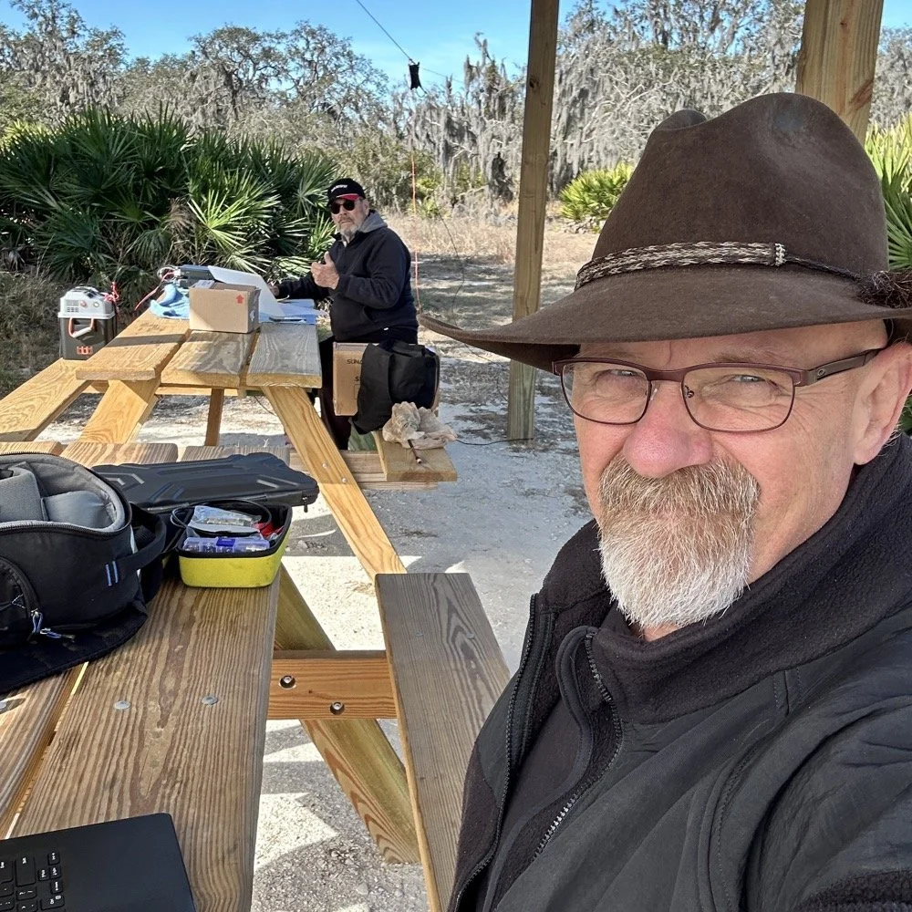
WK4DS (left) and NA2B (right) running simultaneous CW pileups on different bands at Moody Branch
Once setup I used two radios, the Penntek TR-35 QRP rig and the HF Signals sBitx V3. Both of these radios are cool in their own respect. I like the sBitx because I can run FT8 without needing to also connect a computer to the radio. The sBitx will internally log the contacts too so I could theoretically do an activation then when I get back home, down load the contact list and reformat it in ADIF and send it to the POTA site. That is kinda cool. The Penntek TR-35 is small, light weight and has a great receiver in it as well as awesome filtering. This little radio has everything you need and nothing you dont.
Above is me and Chas running pile ups on two different bands at once! We were both running CW today and at times I struggled to hear as my side tone and his were the same. I solved this by adjusting the side tone up a little so then mine and his were different ever so slightly and I could hear mine easily again. I think Chas stayed on 20 meters the whole time today. He racked up 61 contacts with the simple wire antenna. What a day in the field!
sBitx V3 running FT8 with new color-coded software from the open-source development team
This is what you see with the latest software release from the open source team on Github. This software has been made VERY good by this team of dedicated people and if you want to use this software yourself, just follow this link to JJ’s github page to learn more.
NA2B's minimalist CW station: paper logging, pencils, and a clean operating position
Chas had a really clean operating position today. He had plain pencils, which will ALWAYS work, a pencil sharpener and notebook for log data. He was in a blissful state. I also like the battery pack he has too. If I had brought my 36 Ah battery, I would have brought the Scout 555 out and ran it as well. Maybe forgetting it was a sign that I needed to let that radio rest a little…haha. His station looks so clean though, I was impressed.
My station on the other hand looked like I set off a “ham-grenade” lol… I had the logging computer, the foldable keyboard for the sBitx and the whole Penntek station was just piled in the orange storage case. Along with all that, I also had all sorts of other stuff that isn’t in this photo scattered around the table… It was kinda crazy how much crap I brought out.
Operating Highlights
Chas setup his camera and grabbed this photo of us below for the blog. I like how his station has one box on the table and mine is covered in stuff! HAHA!
I will be honest, it was a lot of fun just hanging out while doing the activation. I do so many of these by myself that I forget that I can have someone with me while I do this.
We didn’t get in a hurry, we just took our time and whatever calls got in the log is what we got. There were a couple of time we both had decent pileups to work through, him more so than me as he had more power and 20 meters typically has more operators on the band. It wasn’t about QSO count…till it was… but all day we just made contacts and played radio.
Right before we finished for the day, I asked Chas how many contacts he had. Chas had 60 calls in the log and I had 38. I told him that we needed to have an even 100 calls between us before we stopped for the day. This total number of QSOs was completely arbitrary, but a cool little milestone none the less so we pushed on for a little longer. We finished the day with 104 total calls in the logs. Win! Chas had 61 as a final count and I ended up with 43! What a day!
Multi-operator POTA setup at the pavilion - note the contrast in station complexity!
After about 4 or 5 hours of fun and games, we decided to break down and head back to our wives to get some lunch. It was a great day and I am glad I made a new friend as well.
Activation Summary:
- Park: Moody Branch WMA (US-6317)
- Operators: WK4DS & NA2B
- Total Contacts: 104 (43 WK4DS + 61 NA2B)
- Mode: Primarily CW, some FT8
- Bands: 40m, 30m, 20m, 17m, 15m
- Radios: Penntek TR-35 (QRP), HF Signals sBitx V3, Yeasu FT-891
- Power: 10 watts or less (QRP), 40w on 40m, 50 watts on 20m
- Antenna: Inverted L wire antenna with remote tuner, (Chas ran a random wire)
- Duration: 4-5 hours
You can help support this website by using these Amazon Affiliate Links:
QRP/Portable Radios:
Antennas & Tuning:
CW Equipment:
Power & Accessories:
Organization & Transport:
BONUS ITEMS
73
WK4DS - David

Elecraft T1 Antenna Tuner Review: Field Testing with 41' EFHW at DeSoto State Park POTA
I wanted to put the Elecraft T1 automatic antenna tuner in “remote” location mode to experiment a little with it. This meant placing it at the antenna feed point (that is the BNC to Banana plug adapter you see below. I simply tied the 41’ wire to the red and the 9’ counter poise wire to the black and then ran a COAX from ABR Industries to the radio. I like this coax as it has the common mode choke preinstalled so I dont have to add my other one to the system.
I finally bit the bullet and bought me one of these amazing little tuners! The Elecraft T1 automatic antenna tuner is a marvel of modern engineering and I dont know why I waited so long to get one. I took it with me today to test out and see if it would do what I needed…

Today saw me at DeSoto State Park which is located atop Lookout mountain in the NE corner of Alabama. This park is beautiful an was built during the Great Depression by the CCC (Civilian Conservation Corps) and most of that stone work is still there today. The photo below shows the original entrance to the park and the stone work at the entrance is still there. Today, you enter the park from a different road for most stuff but this road it still open to use and I love going this way just to see these vintage masonry works.
If you are interested in learning more about this park just follow this link to the State park website.


Once on location, I set out to put a 41’ random wire into the nearest tree to the truck so I could tune it to all four bands in the Penntek TR35 radio if I wanted to and kept me from having to dig out the hamsticks and all that hardware. I tied the lower support rope to the door handle of the truck them threw the line over the limb I am pointing to in the above photo and got almost all of the antenna in the air before getting into the branches. It was not shorted to anything, but it was in the branches so I was glad to have a tuner handy to dial it in.
I wanted to put the Elecraft T1 automatic antenna tuner in “remote” location mode to experiment a little with it. This meant placing it at the antenna feed point (that is the BNC to Banana plug adapter you see below. I simply tied the 41’ wire to the red and the 9’ counter poise wire to the black and then ran a COAX from ABR Industries to the radio. I like this coax as it has the common mode choke preinstalled so I dont have to add my other one to the system. This cleaned up the install greatly, but did create one little problem… I had not made up a remote “tune” switch yet so I had to get creative with the tuning process. Since the whole thing was on the truck bed cover, I was able to get the CW key over to the tuner so I could key the transmitter and hit the tune button at the same time.
I already have a plan on making a cable that will allow me to tune the antenna remote from the radio in the future.I will share that once I get it put together, but rest assured that it wont be a long time…lol.

I setup the whole shebang today with my homebrew S meter and the auxiliary system box I made up for the Penntek. You dont know how hard it is to get the display to show the whole frequency during the daytime with an iPhone. HaHa. The refresh rate and the shutter speed are so different that you have to time it to get the whole number to show up. You can see the Elecraft T1 in the background where I had it tied to the antenna. You can also see how I have just slid the key over to tune it for the next band change as well. If you will simply plug the paddle into the straight key input, one of the paddles will act like a straight key allowing you the key the transmitter for tuning purposes.
To be honest, I have used this input in the past when I was trying to use a cheap eBay paddle I had bought to test out for travel. One arm literally broke off and I laid it on it’s side and used the other paddle like a straight key to finish the activation. You do what you gotta do I guess…
Another thing is that it finally turned off cold here. it took it till mid November to find us, but winter is here now and it was kind of all at once too. Like last week it was in the high 60s and low 70s and now it is in the 20s and 30s all day. The cloak in the sun is wonderful though and will keep me warm just fine for things like this. This cloak is make of wool so it is incredibly warm and can quickly become too much if I am active much at all.


Today also saw the deployment of the Gemini travel key as the Penntek has two keyer memories and I dont need the PicoKeyer to work this radio. I could still use the PicoKeyer if I just used the straight key input, but the internal memories do all I need and I like have them in the radio. It just makes the whole system smaller an more compact.


I know that I failed to number the contacts, but this is because I had such a strong run on 20 meters and didn’t have time to write down the numbers. It is over 40 contacts and that is a great day for me in the field! Once I moved to 17 meters I could have wrote them in, but at this point I didn’t see any reason to start so I just omitted them this time. It didn’t matter as I still have a great time and the hunters seemed to enjoy the day too. Thanks for following along and a I hope to see you again soon!
You can help support this website by using these Amazon Affiliate Links:
QRP/Portable Radios:
Antennas & Tuning:
CW Equipment:
Power & Accessories:
Organization & Transport:
BONUS ITEMS
72
WK4DS
Eagles nest activation

Here it is, out in the rocks and weeds. This…this is a POTA activation. Take your radio out into the park, string up an antenna and connect a battery. See who is on the air and make some contacts. Today I decided to simply use CW and use my Ten Tec Argonaut 5 with a speaker wire antenna and my little MFJ 941 antenna tuner.

The kit also includes my N3ZN CW key and my Hamgadgets Picokeyer. These make the Argonaut one of my favorite POTA radios and for good reason, it is a perfect kit. I also have made up a cable that my keyer can connect to the microphone jack on the front of the radio, this is a lot easier than the tiny little port on the back of the radio.
I got the antenna strung up, with my throw-line kit, over the tree next to me as the tuner has the random wire connectors on the back of it. The wire was about 25” long and the two radials were some random length about 15’ or so and it tuned up on 20 meters just fine. It had enough bandwidth that I didn’t need to touch it after the initial tune with the nanoVNA.


I connected the nanoVNA and was able to tune the system fairly quickly without too much fuss. What I like about use the VNA in this application is that the transmitted signal is minimal and I can adjust what part of the spectrum I am looking at so I can find the resonant point and then make adjustments from there and walk it into band easily and visually. As I get closer to where I want it, I simply reconfigure the amount of bandwidth I am looking at and narrow it in. This is only needed if I am using something like this random wire that I have no idea where to start with for it. If it is a resonant antenna, then is is much simpler. Now, to be fair, the old method of keying on empty band space and tuning based on the SWR meter still works fine, but not all of my field radios have SWR meters on them so it is kinda tough to use from time to time like that. This method eliminates the need for a radio with a meter since it IS a meter and can see way more than the simple SWR value. I am once again going to recommend you pick up a nanoVNA and learn a couple of uses for it. Once you do, you will never go back to regular antenna analyzers (which are simple VNA circuits if I had to guess). On top of all that, they are crazy cheap these days too…it is hard to beat in my book.

The N3ZN CW Paddle (This is his little travel paddle with a base plate) and the Picokeyer are a match made in POTA heaven and are now a permanent part of my “POTA Shack” that I travel around with all the time. I take this little key and keyer with me everywhere just in case I have time to activate a park. You know, just in case…lol.


There are two things I really like about the Argonaut 5 in particular. One is that you can key the radio from the front as well as the back for CW. They list the PTT switch as a key input for CW, this is a straight key input only but it is a way to key the radio none the less. I have made up a cable that plugs into my Picokeyer so that I don’t have to use the tiny port on the back that is right next to the heat sink. I also have a RF choke on the line to help prevent stray RF from getting into the radio as well. This does seem to help to be honest about it.If the coax is near this cable it will key the transmitter and add unwanted characters to the CW without the choke inline. That is how I know it works…
The other thing is that the multi-function knob shown above does two jobs at once. So you use one knob to control two different things. The RIT and the Filter Bandwidth are both controlled from here. I normally leave it on RIT once I set the filter to what I want to listen to…usually 500 to 700hz if the band is quiet and 300 to 400 if it is crowded. Notice how well the buttons and knob are organized and even the information that they are displaying is located well, it is literally right above the control so it is in one cohesive place. This is superior engineering in my opinion and is a dying art…

In the photo below I am pointing at the truck where I normally setup to do POTA. That tiny, little, one car parking lot is a great spot if you are in a time crunch and want to play radio for a little bit, but it is really noisy with cars passing by and occasionally one of them is emitting RF noise to boot. This is the reason why I trekked all the gear 200 yards to this shady spot and setup with a battery instead today.


As you can see from the log above, the bands were strange today. At one point I have AE1ZR just vanish and never return… As you can see, I spent several minutes trying to raise him to complete the exchange and he just never returned to my receiver. Several stations took more than one try to get the data through at this time frame actually and I noted it in the log. But when it was open, I was able to work several Canadians as well as Minnesota. Not a bad day in the field with a random piece of speaker wire and a few watts of RF energy…
73
WK4ds
Vintage gear is sus…
When you buy older radio equipment, it is a good idea to check inside before getting on the air with it as this article details about my Ten Tec 277 Antenna Tuner. Sometimes things are lurking inside that neither you nor the person you got it from know about.

I have had this tuner for over a year and have done park activations with it. The 277 also sees extensive shack lately with radios like the sBitx and Penntek TR-35 and such. I had noticed the other day that the sBitx was exhibiting some odd behavior on transmit and when connected directly to a dummy load, it acted normal. So I pulled the cover off of the tuner to have a quick look inside and this is what I found.

These two photos show both problems I found inside when the cover was removed. The first thing I saw was this burnt resistor, which goes to the SWR meter circuit and the wires were broken on the balanced line transformer.

Fortunately for me, neither of these actually impeded performance in how I used the tuner except maybe from arcing on that transformer where the leads were broken if it was still close enough to enable an arc... Probably not though so I am not sure there. The resistor is the 68 ohm resistor on the print that I found online. It looks like it is a simple load resistor to allow the diodes to sample from and was probably overheated by pushing a little too much RF through the tuner at some point in the past. With 86mA of current flow through this resistor, you are at the power limit of 1/2 watt. Doing some simple ohms law, that turns into 5.848 volts across the resistor. I should count the turns on the transformer to see what the primary voltage would have to be to make that happen… lol. That is a whole different rabbit hole though so let’s continue.
When I found these things I decided to go to the internet and see if I could find a schematic of this tuner. Well, the internet did not disappoint. Below is the schematic for this exact tuner.
The bottom half of the page is the schematic for my tuner as it has the SWR meter circuit in it. I printed out the schematic so I could have it on the bench with me during the repair process.
Something I have noted about Ten Tec prints, they lack critical information about things like the transformer ratio or the turns count on the tapped inductor on the matching network or even the turns count on the balanced line transformer, or even the rating of the little meter movement, none of these are present on the print.

To replace the resistor properly involved having to remove the circuit board from the tuner. This involved having to remove all the knobs as well as desoldering several wires to all the board to lift out of the chassis. I will take photos of the areas where I remove wires like this so it is easy to see how to reconnect them later. This is a bonus of the iPhone for me, it allows visual records to be kept in real time of things like this.

Once dismantled, I set out to replacing the resistor first. Sometimes the power rating of the component is just as big of a factor as the value, and I didn’t have a 68 ohm 1/2 watt resistor in my parts bin. What is a guy to do? Well, it turns out that if you put two 330 ohm resistors and two 220 ohm resistors all in parallel that you get 66 ohms mathematically. Mine measured out to about 65.7 ohms or something like that and so I added a 2.2 ohm resistor in series with the other four and BAM! 67.86 ohms! .002% accuracy is good enough if I had to guess, and I upped the wattage rating to 1 watt as well since the four higher value resistors are all 1/4 watt each and they will bear most of the burden of the power dissipation work anyway. (Probably a little less actually since more current will obviously flow through the 220 ohm resistors than the 330s but it will still be way over 1/2 watt total capacity now…) I put it together like you see so it would more easily fit the hole spacing on the circuit board as well as stand up the four parallel resistors to allow better heat dissipation.


Once I had the new resistor installed, I remounted the circuit boar5d and proceeded to reconnect every thing that I disconnected. This is also when I decided to rewire the transformer to the balanced like connections on the backplane as well. With all that done, I reinstalled all the knobs and was ready to test it out.

One last thing I did was tuck the print inside the chassis so that next time who ever is in here will have the information I didn’t and will be able to solve their problems that much easier. Kind of a gift to the next generation as this thing is really robust to be honest about it.


All buttoned up and ready to go back into service in the shack. Thanks for following along on this little adventure.
73
WK4DS
Finally got my sBitx V2 radio…so I went to a park!!!
Quick synopsis is I like it. Read on to see why.
When you see this radio, you think it is like one of the big name machines. It is not. It is actually so much more because of the nature of the project that it comes from.
The HF Signals sBitx V2 is an evolution in their radio designs and brings so much to the table that is cant be described in one blog post…well maybe…I can write as much as I want in one post…lol.

The TR-35’s magic is the lack of menus.
The first thing you notice it the lack of buttons or switches like my Penntek TR-35 has on it in the photo above. There are simply two knobs and a display and that is all you are greeted with at first glance.
Well this is a kind of sleight of hand trick as the display is actually a touch screen and almost all of the controls are driven from this display. In fact, what appears to be at AF Gain (volume) knob, is actually like the multi-function knob on my Ten Tec Omni 7 being selectable for an array of things it can control.
Both knobs are also push buttons and the smaller one defaults to volume control if pressed, but the larger (VFO) knob doesnt appear to do anything when pressed, I can not find anything in the literature describing it so it is there for tinkerers from what I gather. You see, this is an open source SDR, this menas you can download the source code and if you are savvy with coding, you can add features or modify how the radio works to suit you. This is the point of the whole project to be quite honest. This radio does work, but it is not as polished as a big brand machine as it is intended for the owner to go inside and play with things, like add circuits or modify existing ones or even write new features to add to the radio outright. You can literally download the schematic and the actual source code from their GitHub… What ever you want to do, this radio is fully “unlocked” so that you can do it.
Enough about the radio in general, how did it do on the first outing to a POTA park? Well, it did really well, I did power it from the truck battery which means I had to setup in the truck somewhere so the power cable would reach the connection I have in the truck. (I finally added a power pole cable inside the truck cable that is fed directly from the batteries so losses are a minimum.
Back to what I was saying, I got to K-2169 and setup in the truck so I have somewhere to sit this time as I planned to stay a while today and didn’t want to have to stand up the whole time. It took me a few minutes to get it all organized, but once I did, everything fit quite well. I wanted to use my N3ZN key, but to be honest, this arrangement literally made it impossible, so I defaulted to the little travel key I have used so much over the last year. I didn’t have a table top that was convenient to setup the other key on and I even tried to sit the N3ZN key on my clipboard, but it was just too difficult and I kept running into problems trying to use it. Hence you see the Gemini cw paddle in my hand for this activation.
Once I settled on the key and radio, I chose 15 meters to get on the air, the band was wide open and even the propagation report said it would do well… Well, FT8 was rocking pretty strong (I tend to use these guys for my beacon report on a band), so I move down into the CW area and start calling CQ…and I call and I call…and nothing. Seems either no one was on the band or they simply could not hear me. It did appear that the band was fading in and out pretty bad though as the RBN would give me a great report one minute and then it would go 3 minutes without a single update. So after what seemed like an eternity on 15 meters, calling CQ with no answers I caved and went down to 17 meters to see what I can scare up.

The hamstick collection at this point. 15 (Green), 17 (Brown), 20 (Yellow), 30 (Blue) & 40 meters (Red) are all represented here (well, 30 meters was on the truck when I took this photo)

So since I had not edited the memories in the sBitx V2 yet for my use, I planned to use the PICO Keyer I picked up a while back, well it worked somewhat, I think it had trouble keying the radio because the radio is looking for contact closure and not a semiconductor so it would work, but it was introducing errors into the code pretty bad. I finally threw in the towel and just used the key the whole time and ran with it. This turned out to work really well though and I really didn’t mind it after all. Once I got home I built a complete set of memories for the keyer complete with all sorts of messages. You get as many memories as you want, they are in sets of twelve, I tested this by copying the CW1 memory and renaming it then I edited the messages and saved it, rebooted the radio (just as a precaution) and the new set of messages were right there in the drop down menu! They are really simple to edit, but you need a keyboard to do it. I didn’t take one with me on this trip hence I didn’t bother with trying till I got back home. If there is demand for it, I will detail how I added a memory and show how to edit the messages and the message names as well.

So I ended up using almost 4 Amp Hours of energy on this activation. Not bad for over 50 contacts in the log. I am happy with that! When I am going to be at the park for a while, I will get all the antennas out and sort them by band like you see below. Well, they are not sorted at this point, but imagine that they are for the story. Then I can change bands quickly and easily as I will lay them near the mount for the truck. The 2” PVC pipe is maxed out too. I don’t think I can get another antenna in it at this point. If you plan to run hamsticks, I recommend that you get some sort of tube to store them in to protect them. They are not very durable in construction so it would be best to try to store them in a way that will make them last.

You see, I know the radio is transmitting as I have been using it at home for the past week or so before taking it to the field. So I get down to 17 meters, find a clear frequency and start calling CQ here. Well things pick up for me here as I get a few answers so I know the radio is in fact working as it should and I didnt do something to it while I had it taken apart… More on that later when I talk about the mods I did to this radio right out of the box.
So after messing around on 17 for a few minutes I hit a dead spot, so I figure it is a good time to QSY down to 20 meters and see what I can find down there. Well, I found all the ham radio ops in the United States and some from across the Atlantic too! I proceed to make over FOURTY contacts in an almost continuous stream in about as many minutes! I was busy! The radio was working great too. At this point, I clear all the callers and decide to try the lower bands for a minute and see what I can do there.

So I hop on 40 meters first as this antenna has consistently been on the upper edge of SWR for my operating preferences, and the sBitx agreed with it showing about 2.1:1 while I was there. Also of note is that the radio self adjusts the output power based on band and SWR from what I can tell. I was running about 20 or so watts on 20 meters and wihtout changing the power setting at all, jumping on 40 meters netted me 9 watts output into the 2.1:1 SWR where on 20 meters I think the SWR was closer to 1.2:1… So I turned up the drive some in an attempt to get the power out consistent across the whole activation. I didnt get it past 15 watts if I remember right… But it was enough to make a few contacts and get some in the log from more local hams as the 20 meter band hops right over the closer states.
Then I finally moved up to 30 meters to see what it could do as well since that was the only antenna I had not tried yet. Well, 30 meters also did not let me down…like 15 meters did… haha. I got it on the band with good SWR and output power and easily made several QSOs on that band to finish up the HF portion of this activation.
The next part is just for fun, but I also recently got a new HT (Handy Talky) radio and was playing with it while out on this day. So I called into the KG4WBI/R 1.25m repeater to see if Roger was monitoring and he was. So then I asked him to switch his radio to VFO and simplex so we could make a 1.25m FM UHF contact. 5 watts was more than enough to make the trip the roughly 3 or so miles it was to his house from my location! So I netted 54 contacts on this day on 5 bands and two modes. I had a great activation and the sBitx pulled quite a long shift on it’s first outing.
Now to discuss some issues I found with the new radio that I am going to look into solving or upgrading. The first one is actually really easy, it needs a fan… or two. The heat sink got SO hot in the two hours I was in the field operating at about 20 to 25 watts. REALLY hot, the whole radio was hot actually and I think this is what made it start doing the next issue..

This is something I noticed after a while, when the radio is getting really warm, it starts to “stutter” in the refresh rate of the screen. I am thinking this is due to thermal throttling of the Raspberry Pi processor in an attempt to prevent sudden death from overheating. I confirmed this was not due to ram overflow by swapping the Pi out with a second one I own that has 8GB of onboard ram and it did it too with minimal use “on the air” back in the shack at home. So my solution is two fold, one is to install a fan on the main heatsink for the power amplifier in the RF deck and a second fan pulling air through the radio chassis where the Pi is located in an attempt to cool the processor as well. I know this will increase current draw from the battery, but I am not concerned with this as my activations normally don’t run over two hours at a time and this limits amp hour usage to usually no more than 3 or 4 amp hours, which even my smaller battery can handle at this time. If adding the fans runs the draw up to 5 amp hours or even 10 in an activation, then I will just take a bigger battery since this is not a backpacking radio in my book. Also, it did work at 25 watts down to 15 watts, depending on band and SWR, for the whole activation. If I were to just turn the power down to 5 watts, it probably wouldn’t get warm enough to matter on the power amplifier considering the size of the heat sink on it. This means I will probably install a small toggle switch to manually cut the power to the fans should I want to run it at true QRP levels in the field. I also plan to wire the fans through a circuit that will automatically turn them on and off as needed to prevent them from just drinking the battery dry when they are not needed. This involves a small temperature sensitive resistor called a thermistor in a voltage divider and a transistor to flow current to the fan. This way if the radio doesn’t get very hot, it wont come on at all. I think I did the math on this device and it will bias the transistor base at about 105F degrees, which is about right for it to protect the electronics. The processor cooling fan could be done the same way (and probably will) but I don’t want this fan to be very large so I am searching for a small 12 VDC fan for this application and also I want to see if I have room to install the processor heatsink, which is not currently installed. This alone will help tremendously, but with long activations the heat will eventually soak the heatsink and we will be right back to square one. This is why I want to add forced air flow to the system…
Even with all the heat buildup, the radio trucked right along and I put over 50 contacts in the log on the first outing! I even got some from overseas in the log!!! It is always good to get some DX in the logbook. I really liked this radio for a station that will be near the truck. The reason for this is that it is fairly large and heavy compared to my other radios, well maybe the Argonaut 5 is similar in weight. This is one of the reasons the Argonaut 5 doesn’t go on activations that stray far from the vehicle too. That guy is heavy, and it is a fairly fragile radio like the sBitx V2. So who knows what I will end up using it for, but for now, it will be one of my POTA radios.


All that aside, the radio works really well for the most part and over time this will be a wonderful little rig to run on activaitons. I plan to get it going on digital modes as well so I can work contacts on FT8, PSK31 and RTTY as well since it does all those modes natively and without the need for an external computer. This was one of the main reasons for getting this radio, I really didn’t want to have to bring an additional computer to the field to do digital modes… Anyway, with all that said, I packed up and on the way out found a few deer wandering around the area and I was able to get a photo of one of them. That was just icing on the cake for a day with so much activity and fun and getting to use my new radio. So until next week, get your radio out and go make a contact with it!

Testing a new antenna AND CW key during a POTA activation!
I decided to pack up the Argonaut 5 and go activate Cloudland Canyon today to get some much needed air time and wanted to try out my new POTA key that I picked up at the 2023 Hamfest in Huntsville a little while back (actually you will be reading this in the future as I picked up the key last weekend but so is the life of a blog post) So follow along and look at what I found out today while making a few contacts from K-2169.
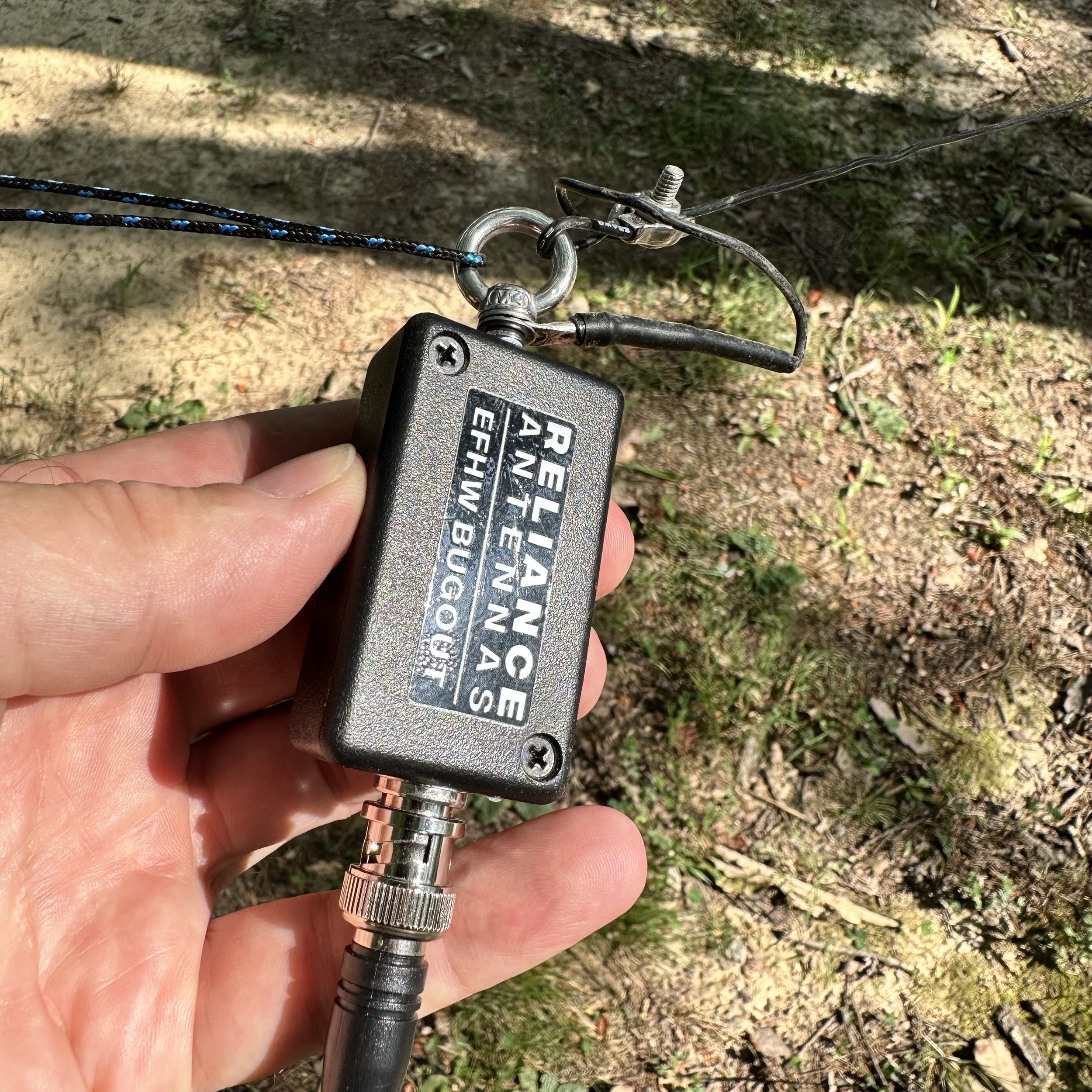
I also decided to do some testing of the Reliance Antenna Bugout 40 EFHW I had bought from N3VAN who was making them and selling them on the QRZ forums. The antenna looks really good with lots of attention to detail in the construction. I have never used an antenna that doesn’t have radials or a formal counterpoise at all. This one uses the coax shield as the counterpoise so, in theory, you don’t need a counterpoise at all. (Come to find out, you can bend the rules of EFHW antennas if you do add a counterpoise) I strung it up in the air between two trees out near the bluff at the park. This may have doped my results, but I am doing a test anyway so why not, right? The far end is about 30’ in the air. The near end is about 12’ up to the transformer and I dropped a 15’ piece of coax down to the radio. Done. Well, so I thought at least.
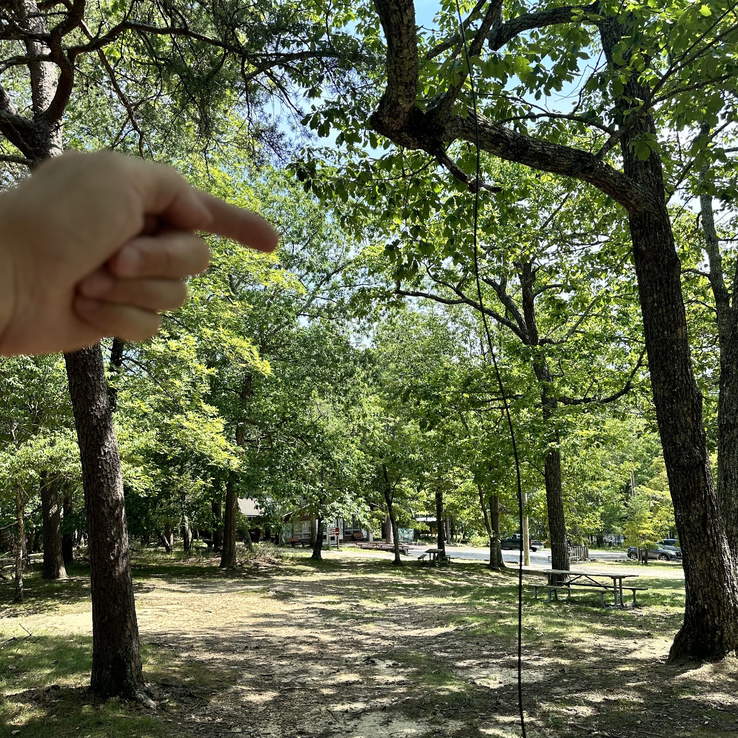
The far end is way up in this bright green tree behind my hand in the back ground. I am pointing to the end of the wire location in the tree.
Once I got the antenna up in the trees, I wanted to see what the plot looked like on the nanoVNA so I plugged it all in and this is what I got. The antenna is technically slightly long and is a little below optimal frequency on this day and rigged like this. I am not going to trim it at this point as I want to see what it does in other kinds of conditions like the winter and maybe right after a rain when it is still wet or maybe where it is set up over night and is soaked with dew. Even though it was off frequency a little in the configuration I had it in, the SWR was well within safe limits for operating any transceiver. I didn’t have a 2:1 SWR at any point when I was testing a particular band and that if fine with me if I don’t have to carry a tuner with me. There was a side bonus to this setup too, for some reason with the whole antenna elevated like I had it, it was giving me a wide coverage (read that as a low q) in the bottom of the 10 meter band. So low in fact, that it was within usable range even on 12 meters without needing any sort of a tuner! That is 40,20,15,12 & 10 in one antenna with zero mods needed. That is winning in my book.

This was the plot without anything other than the 15’ coax going to the common mode choke.
Now get this, I added a radial to the system, but in an unusual location. I put it on the end of the coax on the connector next to the common mode choke right next to the radio and just stretched it out over the ground. This length of wire was 9.5’ in length and when I did this, the plot changed a lot. I lost the 12 meter dip but picked up a much broader area between 20 and 15 meters to the point that 17 meters was below 2:1 SWR at this point. This means that if I add this simple piece of wire I now have a “no tuner needed” antenna that covers 6 bands! Almost everything is usable…sans 30 meters, so I am really happy with this antenna. The next time I set it up will be to test it as a sloper like it would be used if it is a portable setup and I had only one tree to rig it to. Then we will plot it again and see what I come up with. I am curious to see if the frequency of the dips changes with the relation of the end of the antenna to the ground. I dont think it will but RF is a fickle girl…lol.

This plot is the aforementioned setup plus a 9.5’ length of wire tied to the coax connecter at the common mode choke.

This much wire is all that I needed to gain access to 17 meters without having to carry an antenna tuner with me, this is very liberating to be honest. Just adding a small radial to the system makes this super easy to use. The Reliance Antennas 40m Bugout EFHW comes with a winder to store in on as well as a carabiner clip to connect the far end to the cord. The transformer end has an eye bolt that works well for a hoist point to raise the other end of the antenna.

I next setup the Ten Tec Argonaut 5 radio on the table and connected all the stuff to make it work. Once it was powered up and ready, I plugged in the star of the show, my new N3ZN CW Key. He builds some really nice keys and I have walked by his table at several hamfests recently and today I decided that it was time to give one a whirl as they say. So I chose the smallest one he had at the show since I wanted it for POTA activations. The plan is to keep it in the Argonaut “GO BOX” that I built last year. It took me two trips to the field to learn to use it properly too. Since it is so small, if you have a heavy hand when you send it will move around a lot on you. The trick is to set the action light enough that you just have to touch the paddles to send the code, this way it is a light operation and the key stays put on the table like it should. These keys come with the cord hardwired to them so you cant buy a simple aux cable and plug it into the key, but it didn’t cause me any trouble so I don’t mind it. The installed cable is high quality and I have no doubt that it will last a very long time.

Once the antenna was squared away and I had my 17m “element” nearby, I was ready to crank up the radio. The new key plugged into the keyer I recently acquired from eBay and we are off to the races! Or so I thought as it turned out that KJ4BAD happened to be walking by and stopped in to see if I was doing POTA and we had a great chat for about 10 minutes or so about all things radio. I always enjoy running into other hams while out at a park.

I really like the Ten Tec Argonaut 5 radio, it has almost all of the CW functions that I use are on the surface. There is a could of things that you hit a button and then make the adjustments and you are good to go. The other thing that is great about this radio is that it has 20 watts of transmitter power. This is awesome when the bands are not as good as they were back in the winter. Also the DSP filtering works surprisingly well. It is also really good with other modes, but I just use it for CW… I might make a cable at some point to put the key into the front socket instead so it is simpler to connect the key. You see the mic key will key the radio so that means my little memory keyer will work in that socket. Who knows when I will do that though…


After we finished chatting I settled in for some POTA therapy and dialed around a little to find 15 was open with a bunch of stations on the air. I setup and start calling and you can see in the log that I only made two contacts before giving up and moving to 17 meters where I usually make several contacts but today I only netted one. Things were looking pretty dismal till I went to 20 meters. Once on 20 things turned around for me. I fairly quickly got the activation and proved out all the gear I had brought that day.
This photo shows where I would place the extra radial on the Coax connector. The coupling between the common mode choke and the feedline made for an easy spot to add it. I simply stripped the wire back a little and twisted the wire over this point. Simple as that. The easiest mod I have ever done to tune my antenna to another band in the history of ever.

This was the view I had today while operating, this is why I like POTA over other activities. The view is epic. So there you have it. My POTA “test and tune” trip in a simple blog post. Until next time, 72.
de WK4DS
Simplifying antenna tuning with a manual tuner and a nano VNA on location.
Please note: This is not an instructional presentation on how to use the nanoVNA to tune your antenna, but rather a simple primer on how I deploy mine in the field and why. There are tons of videos on YouTube that will show you how to deploy the VNA in a tuning operation and at some point I will probably do that here, but I wanted to share the idea of USING the VNA to tune the antenna WITH the antenna tuner prior to hitting the transmit key and protecting your radio transmitter finals. With that out of the way, let’s dig in!
Something I have always hated doing is the whole tuning operation and transmitting while I did it. Just screams of poor operating practices to me for some reason. I know it is needed though, so I do it… Till now. You see, some radios don’t have an internal antenna tuner built into them, like my TenTec Argonaut 5. This radio is a joy to use but you either need resonant antennas or a tuner to match the radio to the radiator.
Enter the nano VNA (Vector Network Analyzer)… I found out about these little devices from my friends Aaron and Roger and finally got one for myself. Back in the day, about 15 years ago, these little pocketable widgets would set you back about 20,000$ and were the size of a suitcase! Now, technology has caught up and these things are very affordable (about 50$ US) and are even battery powered so you can take them to the field easily.
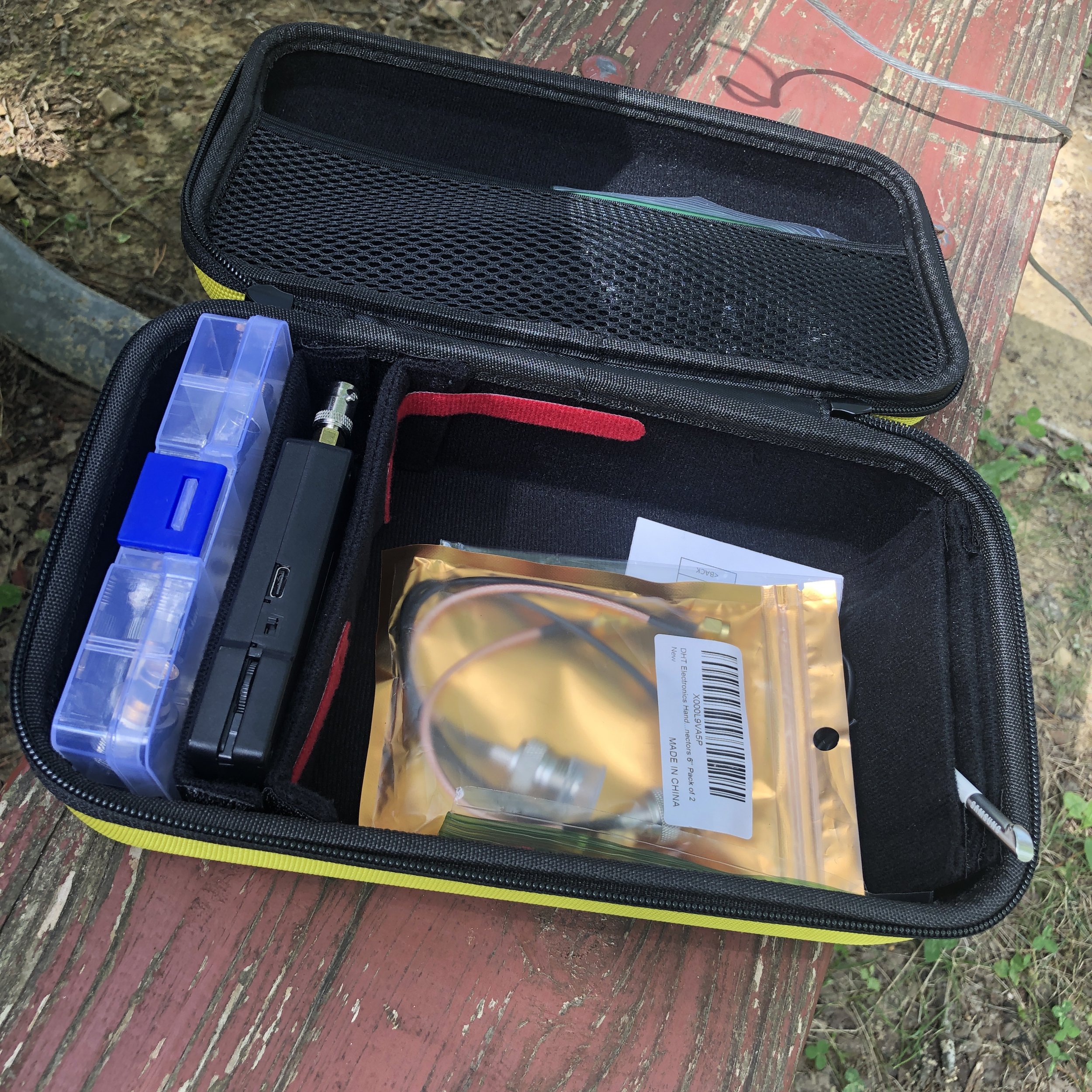
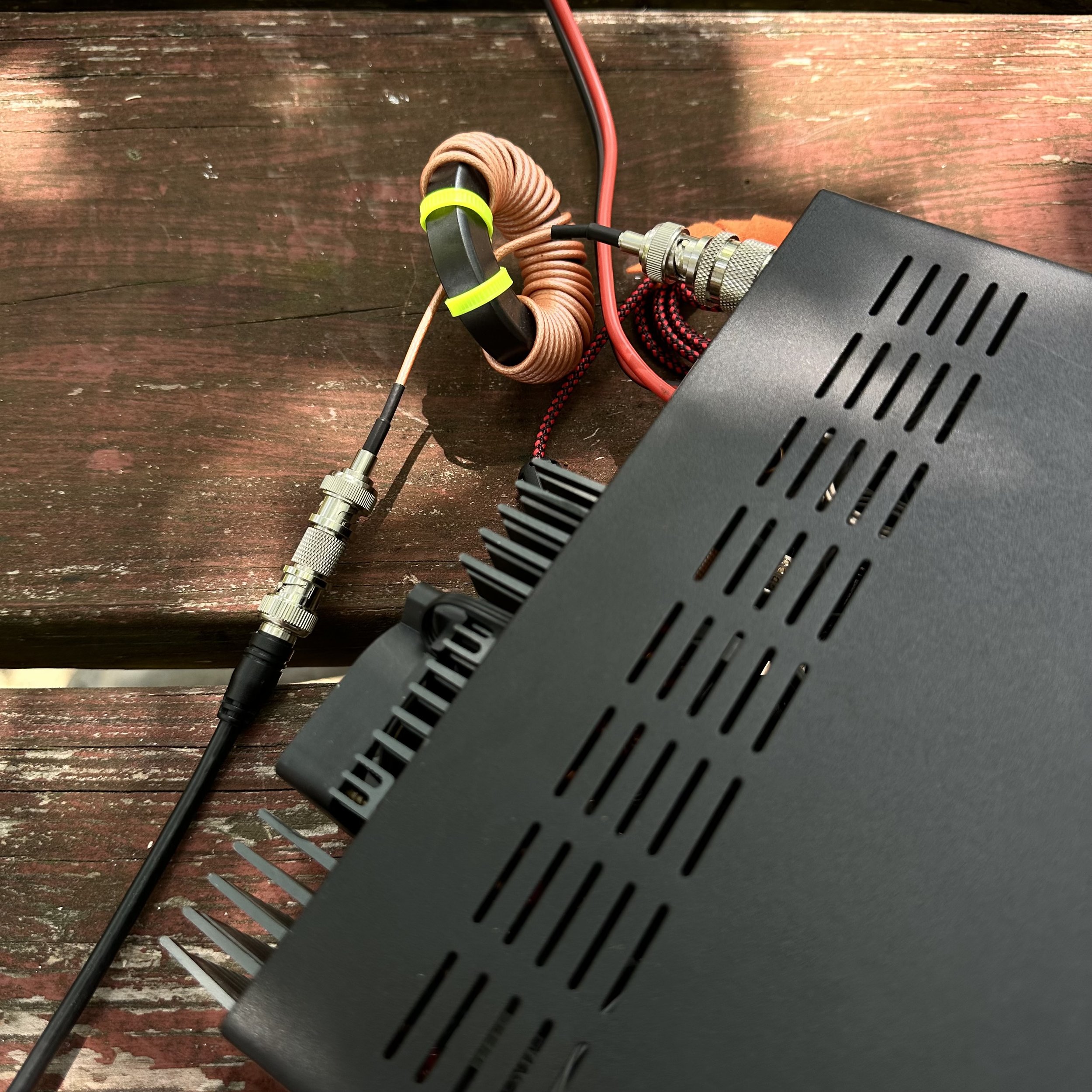
I built this kit for mine with a divider box of adapters (far left in picture), then the nanoVNA is the black device next to that, then the large bin is for cables and such and lastly I have a stylus as it is easier for me to use that than to use the guitar pick looking device that comes with it. This one is recovered from a old Samsung Galaxy Note. I got the case at the Huntsville Hamfest from GigaParts if you want one of them, they probably have them on their website, but I am not sure…
This thing can do all sorts of measurements, but the most often used by me is antenna tuning. If you want to know more about what it can be used for, just search YouTube for nanoVNA and you will get an idea.

In this photo you can see a lot of data being presented on the nanoVNA, such as the frequency range I am testing, two different measurements, one on a smith chart and one on a linear line chart of SWR versus frequency. What the smith chart shows me is a graphical representation of whether the load (antenna) is capacitive or inductive, and what the impendence is at the selected frequency as well. The line graph shows SWR plotted versus frequency and this allows me to maximize the tune for a particular frequency visually, all without risking damage to my radio amplifier section from mismatched impedances or high SWR. The nanoVNA does have a signal generator in it so it is technically transmitting, but it is VERY low energy.

Manual tuners in the past, such as this vintage MFJ 941 worked really well, but are slow and you only get information for the exact frequency you are tuning at (which usually is not the frequency that you are going to use as you dont want to tune up on top of the person calling CQ). This meant long periods of on air transmitting a carrier tone while adjusting the controls on the tuner to add capacitance or inductance to the the antenna to match as best you can so as not to damage the radio.

Radios like this old Ten Tec Argonaut 5 do not have automatic internal antenna tuners in them and even a lot of newer radios don’t have these tuners in them to be honest. These radios either need a tuned antenna that has been built for specific frequencies or a tuner to match the non-resonant antenna to the radio. The nanoVNA allows the operator to tune easily and this happens much faster than on air tuning. Tuning this way also protects the radio in the process. What I really like is that I can see if the bandwidth of good matching SWR to the radio so I know immediately that I can tune the VFO around and not have to retune the antenna while I am on one certain band. Some antennas and some bands don’t play well together and you can see this too… graphically. This allows you to know that on those particular bands, you will need to tune when you leave the safe zone of swr. It is so much more powerful to tune your antenna with this little device.

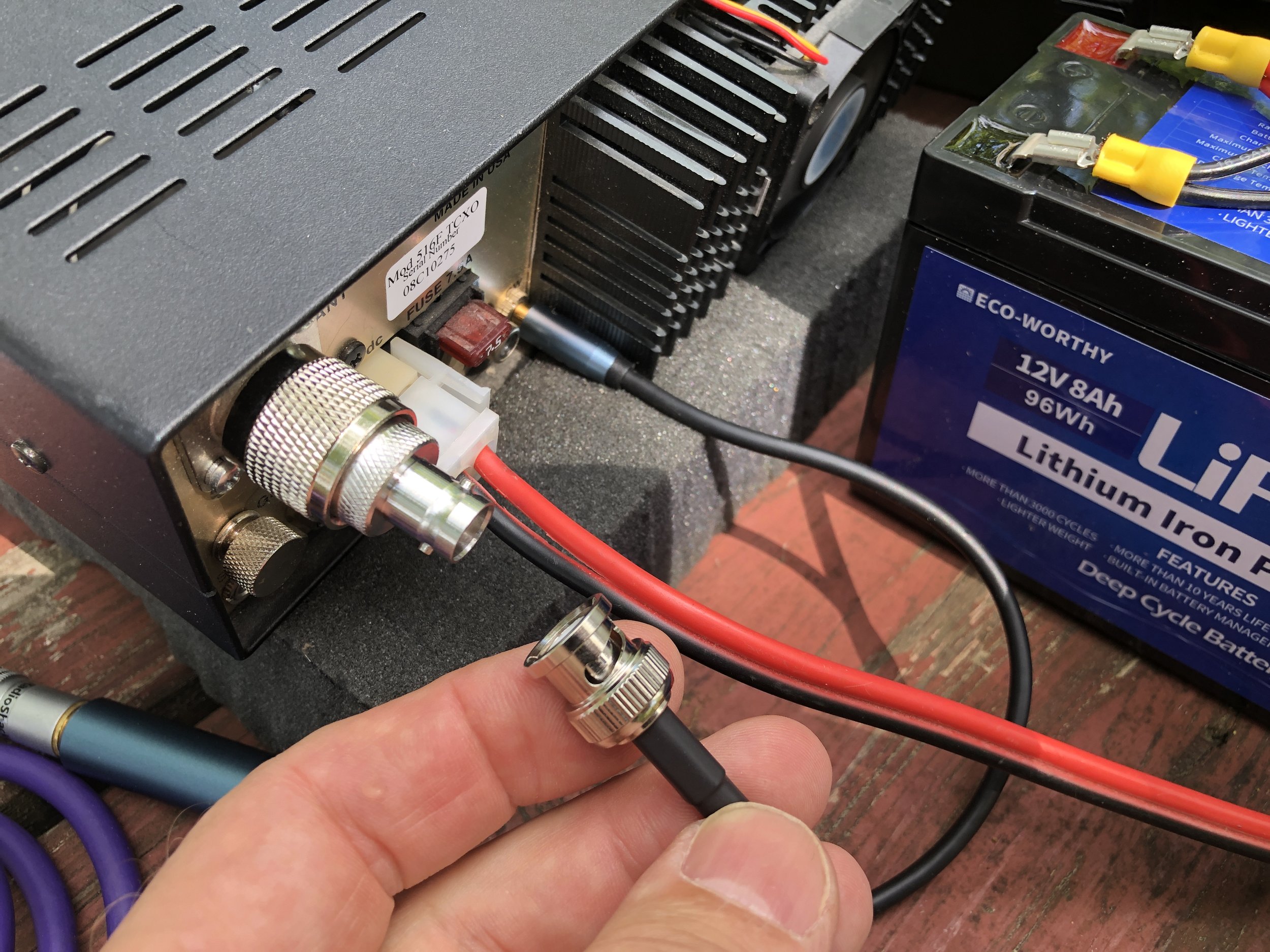
This is the setup I use to be able to easily connect the nanoVNA to the antenna while out on location. The radio comes equipped with SO239 connectors so the antenna has to be screwed on to the radio with a coax cable normally. The modification I made, to make this process super fast, is to add a PL 259 to male BNC adapter. Then I add a SMA to BNC to the nanoVNA and now I can simply and quickly remove the coax from the radio and connect it to the VNA for analysis.
I also made a simple note page to get me close when i go from one band to the other. This way the time to get back to a tight tune is even faster. I also made some notes about how many radials and such. I keep these notes in the case with the radio and tuner.

This has been my biggest blog to date and I really liked writing this one for you. If you have any questions, just drop them in the comments below and we will try to get you an answer as soon as possible. If you think tuning your antenna like this is a good idea, you can find these on Amazon with a simple search. Also, they really are inexpensive. You can also get all of the adapters or accessories on amazon as well. It is all there, all the training you will need can easily be found on YouTube as well, plus some… Now go get on the air!
72
David
WK4DS