WK4DS Amateur Radio Blog
Search Posts
Back on the Air for a POTA Activation
Today saw me back at US-2169 for the first time in a while…
Today saw me take the old Dodge over to my local park (US-2169) for a short activation. I have been busy in the machineshop these last few weeks so there has not been much time for POTA. I have actually not been to a park in several weeks and was starting to miss it.
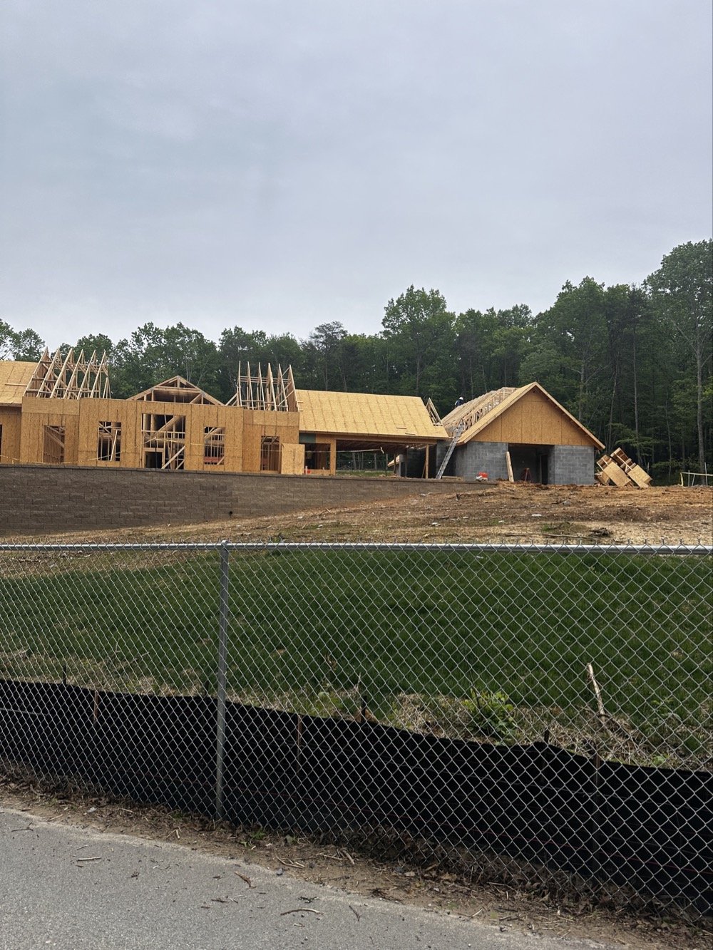
Update on the park visitor center upgrade in progress. The grade work is done and they are framing the new building at this point. It is coming along nicely too.
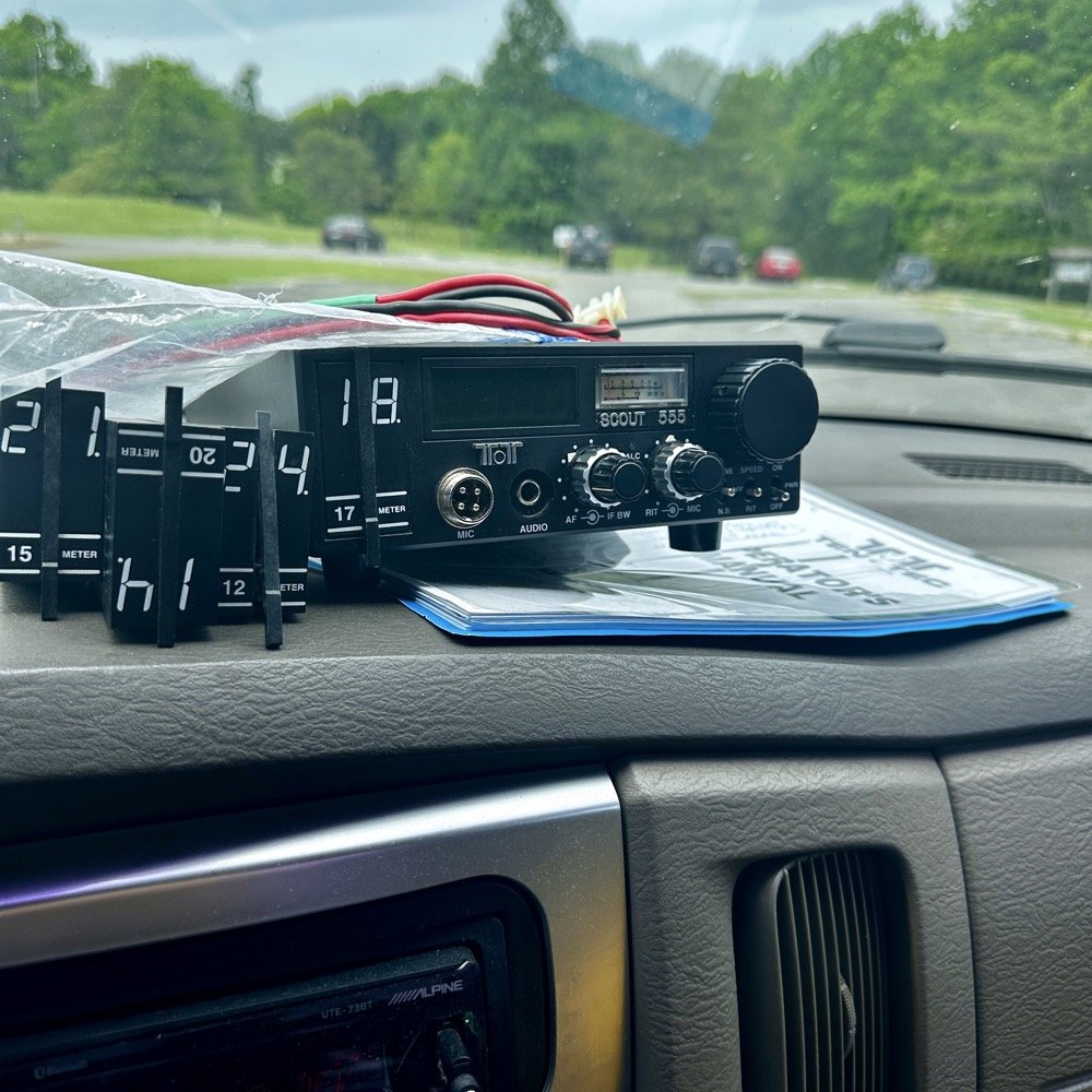
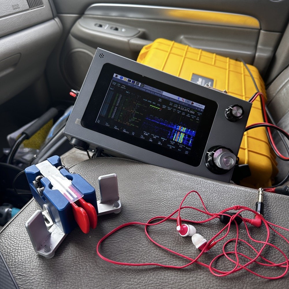
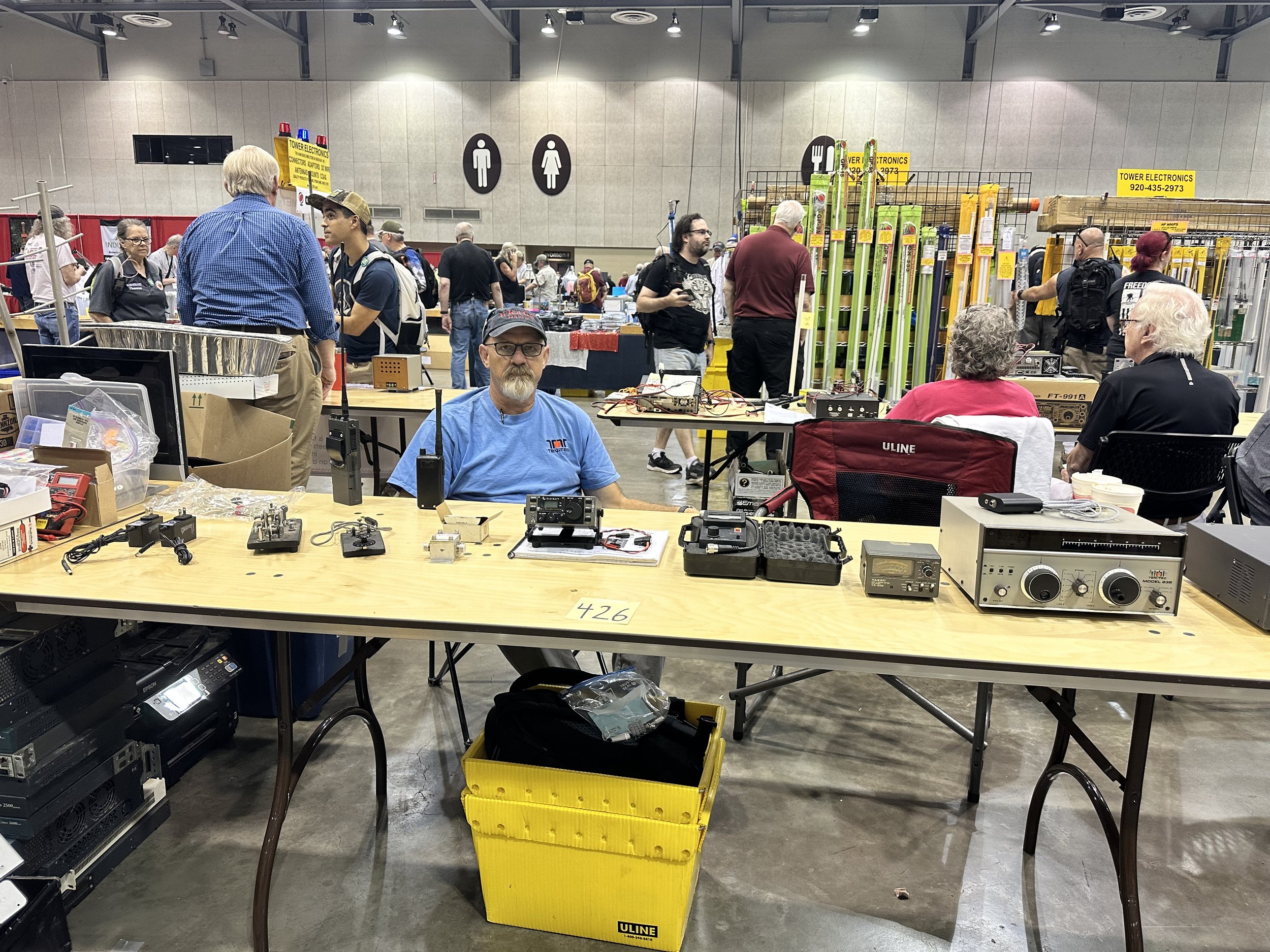
Setup of my POTA rig for HF operation
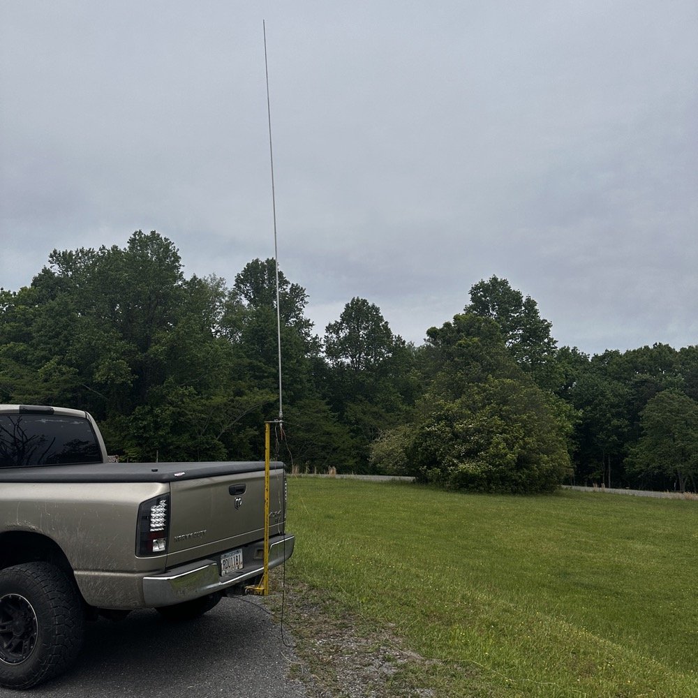
I went up to the frisbee golf course again as this is a great place to setup for POTA. A lot of people will use the nearby pavilion when they setup, but my antenna mount, being attached to the truck, makes it alot easier to operate from the truck. This is an amazon 18’4” whip that I bought, you can get one too at this link: Link to 18’4” whip on amazon Now, to just let you know, this is an affiliate link, but it doesn’t change the price from what I can tell… At the time of this writing, they were on sale for 27$, which is incredible!
Today I used the 18’ 4” foot vertical telescoping antenna and two radials attached to the base. Then ran a coax into the cab of the truck to the front seat where I normally set up the radio in the front passenger seat. Something I noticed today was that no matter what band I was on, the SWR plot would never get better than 1.5:1 (which is perfectly fine BTW) but I can normally get way better matches with different radials, which tells me that the radial length is more important that people let on…
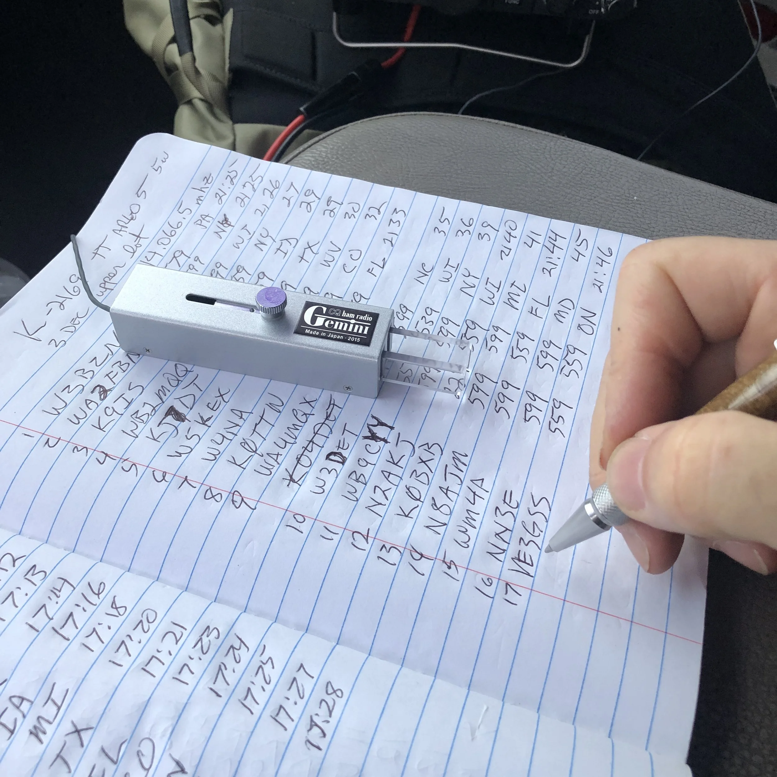
Next, I chose the TenTec Scout 555 as it is a wonderful CW machine. It does have a little bit of drift in the VFO, while it warms up, but it is not enough for me to worry about. I started on 20 m in the CW portion of the band and hunted stations to start with. I worked another POTA site for a park to park contact before finding my own space and setting up there. I made 19 CW contacts on 20 m before I decided to move to 15 m to see what I could find there next.
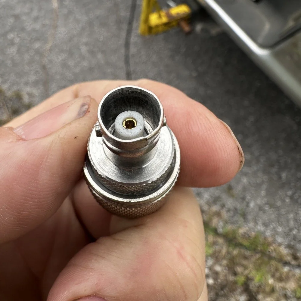
Pay attention to bad antenna connectors…
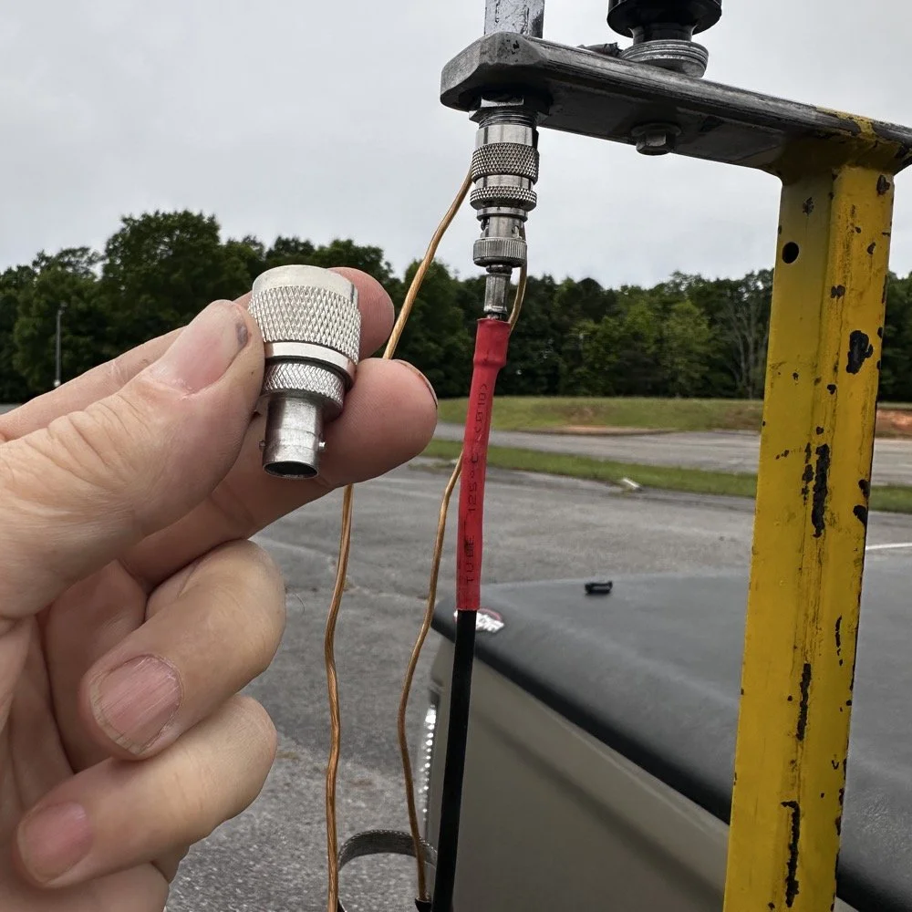
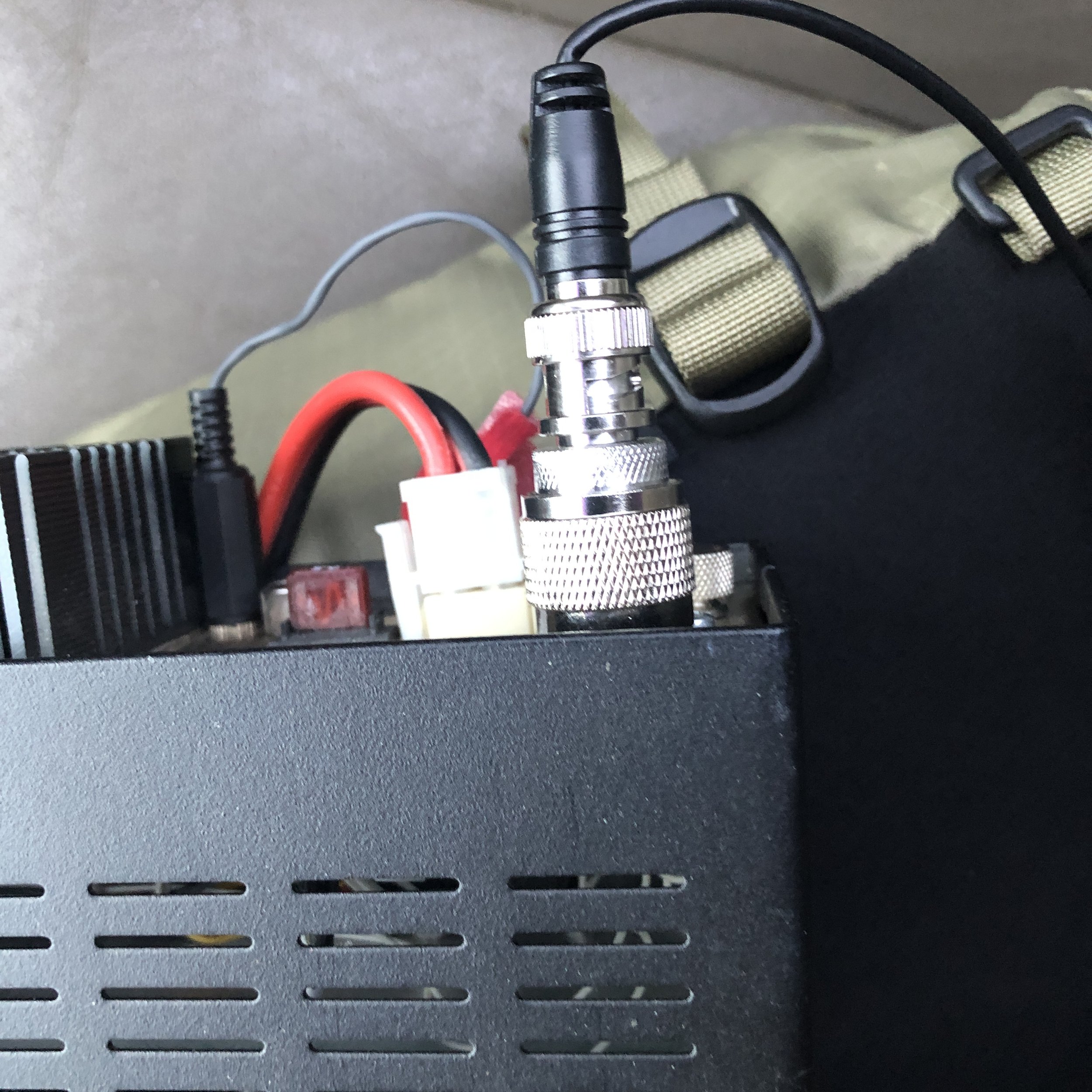
When connecting the antenna today, I had trouble getting the BNC to attach, upon closer inspection I had found that it was crushed from impacting something in the truck… Probably when it was in the red Chevy as there is less protection in the back of that truck as compared to how I store it in the Dodge. Oh, and yes, my heat shrink tubing on the coax has slipped back for some reason. I noticed it when I was breaking down and simply slid it back into place…haha. I did not notice this until I attempted to use it today to operate this activation.
I attempted to straighten the damaged BNC connector with my Leatherman as best as I could, but it didn’t work really all that well so I got in my adapters for my nano VNA and robbed the one that was in that pack and used it instead.
This is a great example of why you always carry spare parts for all of your connections so that you don’t get shut down because of something getting broken unintentionally that you are not aware of.
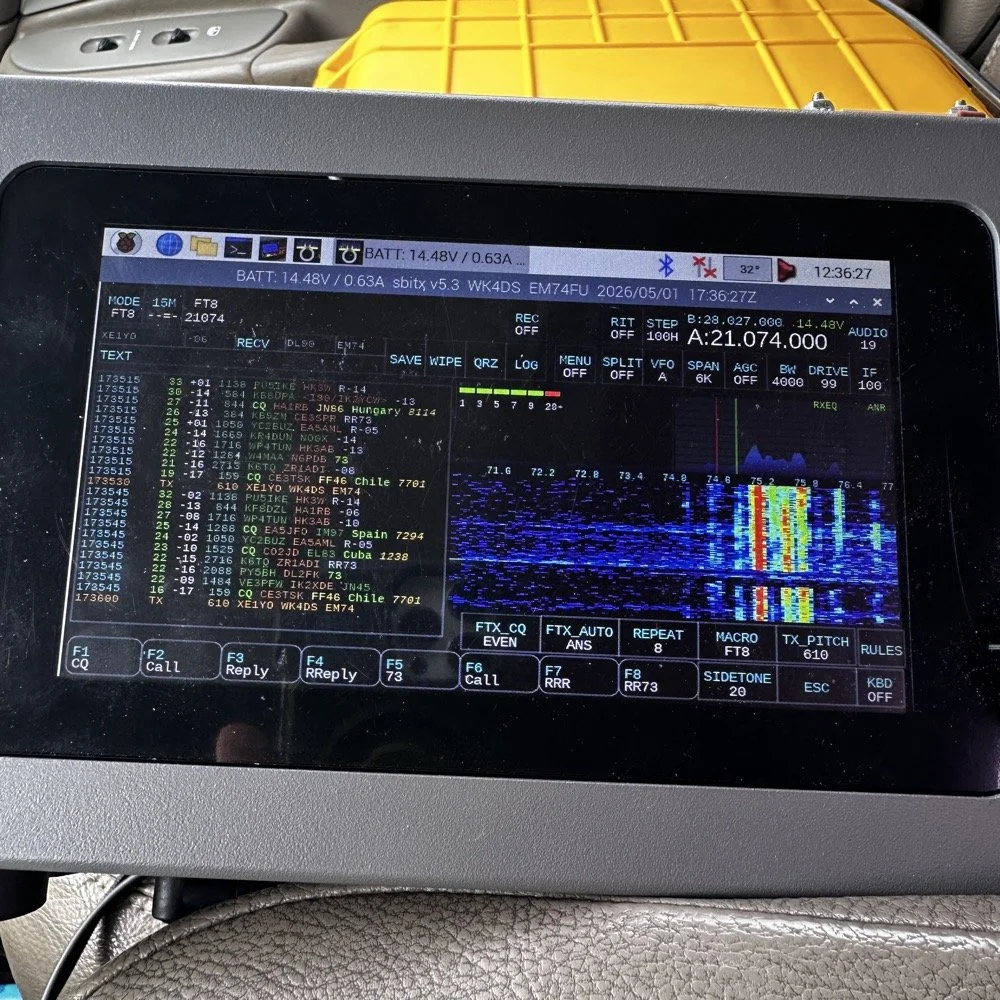
The HF Signals sBitx V3 and native internal FT8
Once I finished working CW on the Scout 555, I decided to get the sBitx out for a while to work some FT8. I really love using this radio for FT8 and CW in parks, it works so well and with the version 5.3 software, it has a metric ton of great features. The waterfall works well and the automatic modes in FT8 are really handy too. This radio is 25 watts on the lower bands and trails off to about 12 watts on 10 meters. This is plenty for me as I work a lot of QRP anyway so little to no power output is fine for the most part. Would it be nice to work with more, yes, but I can manage without it just fine.
Today I only used it for FT8, but I also will use it for CW from time to time. It is a little temperamental in CW since it is a Raspberry Pi 4 running in the background, but once you learn the keying, it works fine up to about 23WPM for me without too much issue. Using something like the Begali Traveler CW Key in the photo below also makes it more fun too. A really nice key is always a good thing to have with you.
Once I worked a few FT8 contacts on 15 meters, I dropped down to 17 meters and worked a few more there before shutting down for the day and heading home.
I noticed when I was getting ready to leave that the truck motor was “squeaking” when it was idling and when I investigated further, I found that it was a pulley on my fan belt had a bad bearing in it. So I went to the auto-part store and got a new one to replace it with. Once home I was able to replace it in short order so that I would be ready for the next POTA outing that I wanted to go on. Sometimes things just come up and you have to take action…haha.
Thank you for following along and I look forward to sharing something with you again soon, till then 73!
You can help support this website by using these Amazon Affiliate Links:
QRP/Portable Radios:
Antennas & Tuning:
CW Equipment:
Power & Accessories:
Organization & Transport:
BONUS ITEMS
![Building a 60m Band Module for Ten-Tec Scout 555: Crystal Selection & Filter Design [Part 2]](https://images.squarespace-cdn.com/content/v1/5d17806ce65eba00011667cb/1768486316134-5KK47YMDB3P45BK25B4N/IMG_1141.jpg)
Building a 60m Band Module for Ten-Tec Scout 555: Crystal Selection & Filter Design [Part 2]
I figured the the mixer’s bandpass filter would be the same as the IF filter but turn’s out I was wrong here. I looked at the existing part values on the chart for 40 meters and 80 meters (remember that part about not having a formal education in this stuff?) and simply decided that the inductors were again too big and I needed them to have a slightly lower value instead.
Well, if this is the first post of my blog you have found about the 60 meter band module, please Read Part 1 for the complete background on this project. or a lot of stuff is not going to make sense…haha.
The donor about to undergo surgery to become a 60 meter band module.
As you know from last week, I was able to get all the filters updated except the output bandpass filter for the mixer and changing the crystal, so let’s get into that today.
I figured the the mixer’s bandpass filter would be the same as the IF filter but turn’s out I was wrong here. I looked at the existing part values on the chart for 40 meters and 80 meters (remember that part about not having a formal education in this stuff?) and simply decided that the inductors were again too big and I needed them to have a slightly lower value instead. This is where things get engineery..is that actually a word? It should be. I started by simply using an online calculator to figure the values for this filter based on the chart from NA5N’s Website and my own simple math of a mixed product of 11.442 mhz. It falls right in the middle of the 80 and 40 meter LO frequencies on his chart. So now I needed a crystal…
Luckily I didn’t need matched sets like when making a crystal ladder filter so I was able to find 9.218 mhz crystals on Digikey for reasonable money. The calculated crystal frequency I came up with was 9.242 mhz to land at 5.300 mhz. This radio will absolutely transmit out of band and it is the responsibility of the user to stay in legal band space so I figured this would cover the entirity of the 60 meter band. The NA5N chart shows the PTO minimum frequency is 2.2 mhz so that is where I started my math.
2.200 mhz (PTO min.)+9.218 mhz (PTO XTAL)=11.418 mhz (LO) - 6.142 mhz (IF) = 5.276 mhz
The entirety of the 60 meter band is from 5.3305 mhz to 5.405 mhz so this will work perfectly fine.
All this math starts to make sense when you look at the chart at the bottom of this page. That is why I keep linking it…haha. So I build out the band pass filter and install the new crystal when it comes in and … nothing… Well, it did something actually. It would not lock onto the frequency at all, it would attempt occasionally, but most of the time it would just scroll numbers on the display of the radio. It obviously was not working. I was sure I had built the filter right… (turns out I was dead wrong…again…I am starting to see a pattern here…haha).
As I would soon find out, I built the filter for the 40 meter IF by accident. At this point I had a lot of numbers floating around in my head and scribbled on various pages laying around the bench and one was where I had done some of the math around the 40 meter circuit for some reason and I inadvertently used those numbers to make the inductors with. Couple this with a trip out of town for a week and you will see where I lost my train of thought. Once I returned from the trip I had just two days before leaving again to see what I could figure out.
Well, this is what I figured out.
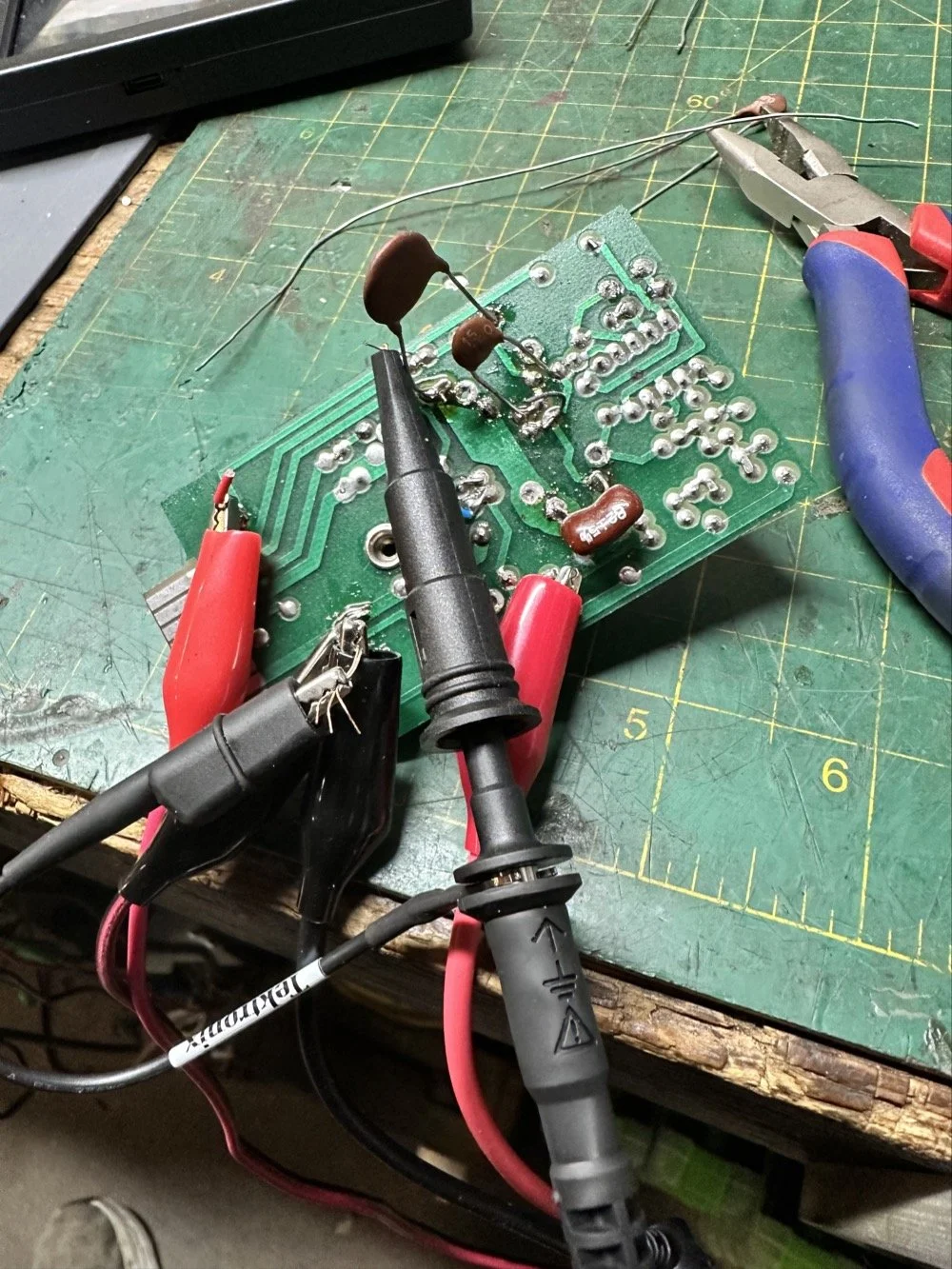
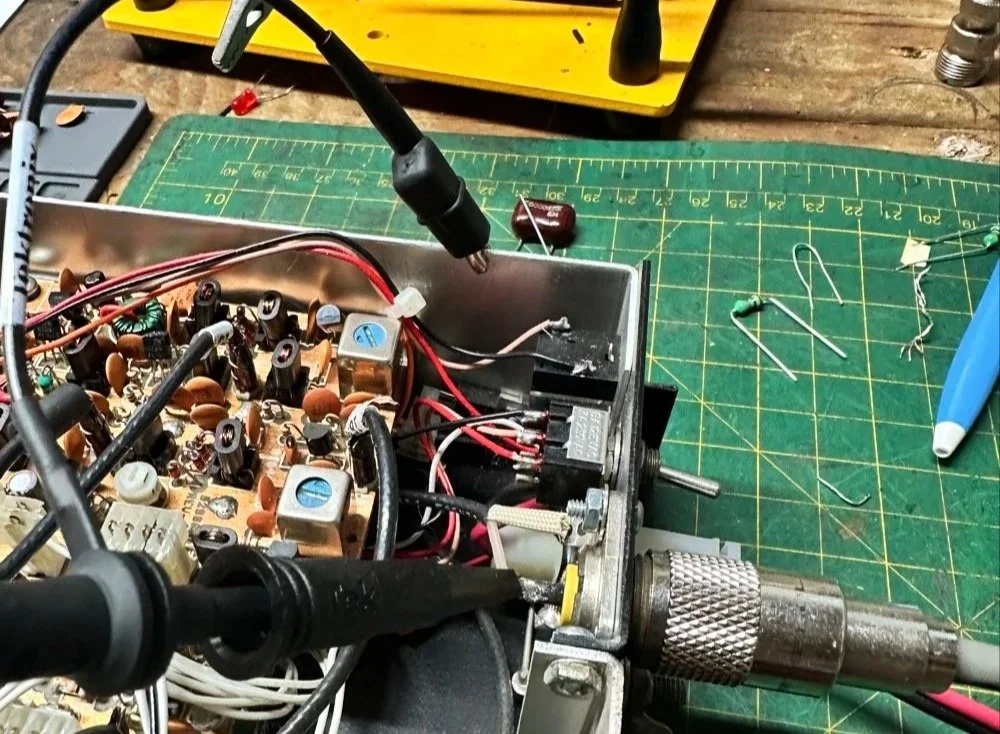
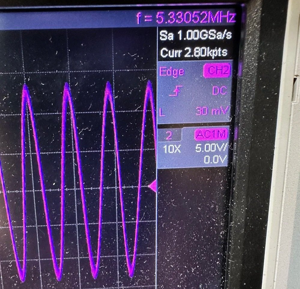
What you see above is a frustration point to be honest. I studied the print long enough to realize I could bring the circuit to life if I had a signal generator and a power supply. To get this to work I soldered several small scrap clippings from component leads to the board in strategic places to be able to connect leads for various devices and you get what you see above. I immediately went down a rabbit hole on signal generators and ended up with a UNI-T UTG962E and it arrived THE DAY BEFORE WE LEFT ON OUR TRIP. I get it going and power up the circuit with the 10 VDC bus and then inject a 2.2 mhz signal from the brand spanking new signal generator into the line (simulating the PTO) to see what I would get at the output… well… nothing. I checked the crystal and I had a clean 9.218 mhz signal at about 700mV going into the mixer chip but my 2.2 mhz injected signal was 50mV (the signal level based solely on the output shown on the block diagram going into the receiver control board as the data sheet for the chip I found didn’t show a signal level threshold that I could find.). This was obviously too low and I started turning up the signal generator and nothing happened at first. I was at 700mV of signal level coming out of the generator and I was getting nothing at the output of my filter. So I start walking it back to the output of the generator. I didn’t have anything at the output of the mixer chip as it turned out, so I check the inputs to the chip on the chip directly and the PTO input was almost non-existent. Turns out that the output impedance of the signal generator and the input impedance of the low pass filter for the mixer chip on the board must be different as it was dropping the level pretty dramatically. (This is something else I have learned while doing this project, you have to observe the impedance between stages or it wont work. ) So what do I do to solve for this? (Remember again I have almost no formal education in this area of expertise) I simply put the scope on the output of the mixer IC itself and slowly start turning up the 2.3 mhz amplitude till Eureka! The mixer sprang to life and I had a product!
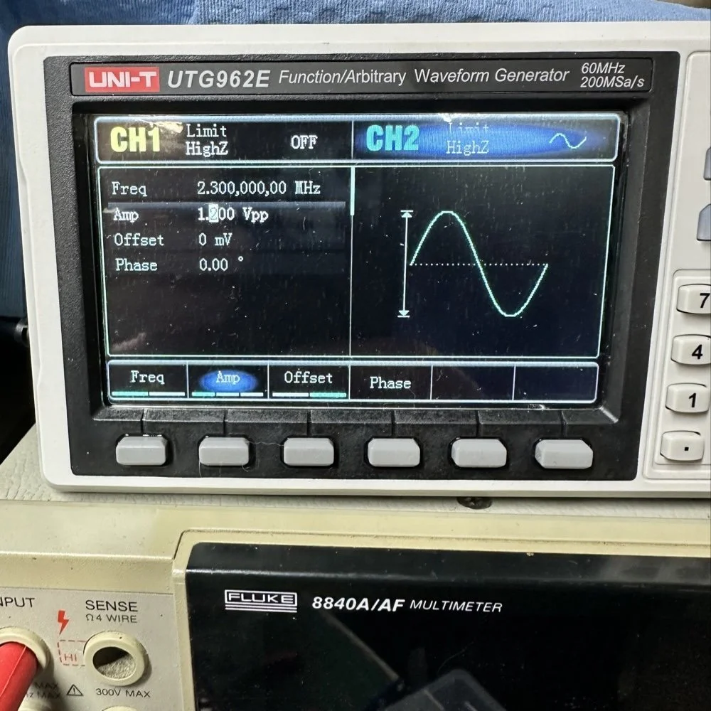
Note: I am using a different value here for the PTO reference signal because I didn’t notice that I had changed it till I got the mixer working. But it is fine as the PTO operates from 2.2 mhz up to about 2.7 mhz anyway. The key was getting the bottom of the mixed product below 11.425 mhz when the PTO is at minimum. This will allow tuning through the 60 meter band. But this is why the number in the photo below is 11.520 mhz and not 11.425 mhz.
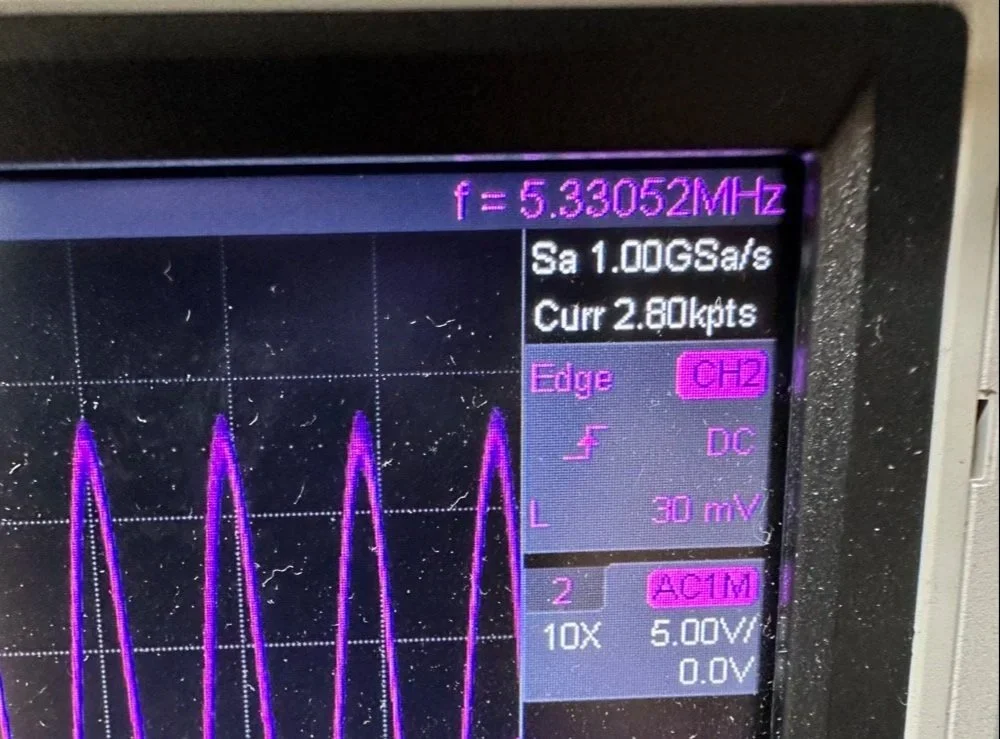
Now that I have a signal coming out of the mixer IC, I need to see what it going to the receiver control board. You see on the signal path drawing from the NA5N site that he states it should be 50 mV or so there. Well I had nothing coming out of the band module at all. I start looking at the filter and this is when I figure out the filter is all wrong. Back to the drawing board again. I take the week long break and during this time away I dwell on what I had learned and spend even more time trying to learn how this bizarre filter works. It looks somewhat like a regular band pass filter but there are elements that don’t make sense to me. I spent a considerable amount of time studying this problem and decided to order some inductors and when I get back I could replace my home brew ones and see if I had done something wrong there.
Fast forward a week and I went home and had about 5 hours total to figure the whole thing out or it would wait yet another week… I start by replacing the two home brew inductors with two 2.2uH inductors from the variety kit I ordered. Still didn’t work, so there must be something wrong with the capacitors too. All of the caps at this time were class 2 capacitors so that would turn into a problem as they warmed up, but this thing was not working even when it was cold, so the values were wrong is all I could figure. The most logical thing was to strip them all out and start over. I had now gotten my hands on some NPO caps too, this allowed me to build out the filter completely with the correct rating capacitors thereby giving me the confidence that once it is working, it will hold value.
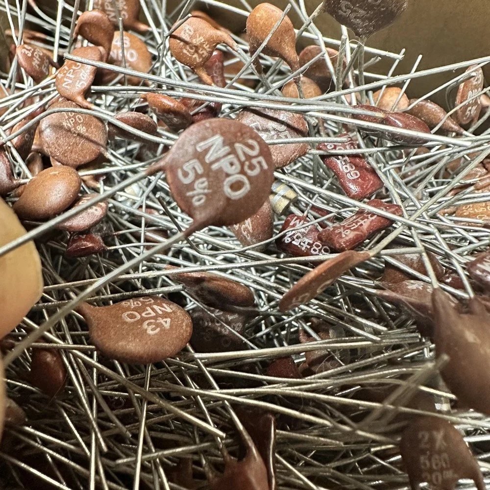
My first batch that I bought was a literal double handful of random NPO capacitors (and a few other ratings mixed in for fun) thrown into a box from eBay. I knew what I was getting so I also picked up some divider boxes to sort them when I got time. Now they are all sorted and I know where to find what when I need it. Of course, I don’t have every conceivable size to choose from but I do have a large assortment and can get by with most projects with what I have. Things like this are what I wished I had learned in trade school… I guess I should have chosen college instead…you know what they say about hindsight though...
The photo of the board above that shows all the leads connecting to temporary test points I soldered to the board has these capacitors on it. They are temporarily soldered on as I am experimenting with various values in different locations to see what will get me to where I need to go.
I tried to use the online calculators but this filter doesn’t fit into any of those models and all the outputs from those tools were not working for me. It looks like the coupling capacitors are also used to also limit the signal level from stage to stage as well. Correct me if I am wrong in this assumption, but tiny little 5 and 8 pF capacitors are not letting a lot of energy through them, even at HF frequencies and there are two in this filter circuit. I can only assume that they are also using these to match impedance as well or a larger value would couple the stages with more signal. Anyway, I was stumped and asking the internet for help is literally begging to be slandered and chastised for being stupid, so I didn’t even bother with that option. That only left experimentation and experimentation is what I did. I put all sorts of outlandish caps in this filter and found success doing it this way. It took me a few hours, not gonna lie, knowing how to calculate these sorts of things would have been immeasurably easier, but I was able to get the signal on the output trace of the band module and it had decent signal level too! Honestly, I am going to revisit the output signal level when I get back home (I may have already done it by the time this goes live on my site) and see if I can attenuate the level somewhat as it is higher than what the base of Q16 on the receiver control board shows in NA5N’s pictogram.
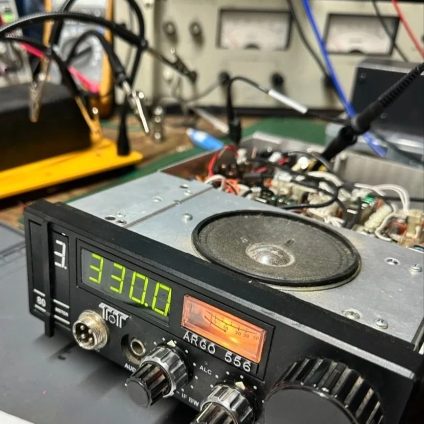
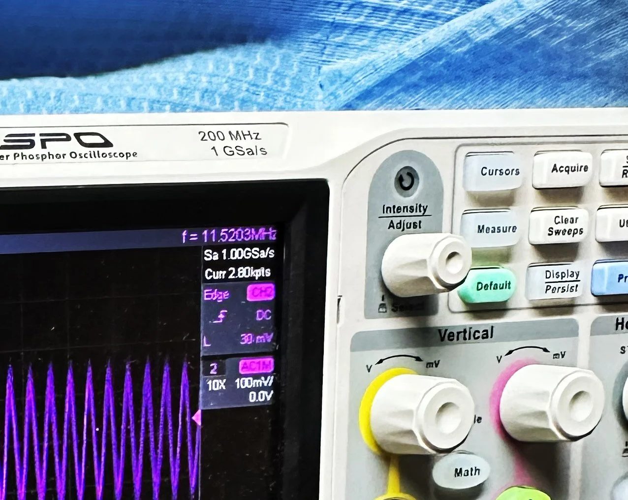
What you are seeing above is the output of one of my Argo 556 radios that I used as a test bed to check the signal levels and such to see what was going on with it. As you can see I simply connected to the output of the radio and looked at the signal going into a 50 ohm dummy load. I did the math (I know, I know… this has not been a great idea for me in this blog post… lol) and it comes out to about 1.8 watts and not 5 watts for this radio (I have not attempted to turn up the transmit power on this unit yet either so it might simply be turned down or something like that. Let me know if my math is wrong here, but 27 volts peak to peak and 50 ohms should give me a power level of 1.82 watts at the antenna connector?
Power= peak voltage (13.5volts) divided by the square root of 2 and then that is divided by resistance.
All that aside, I took the newly minted 60 meter band module up to the shack and setup a Scout 555 and connected it to my home antenna. Tuned the antenna up and started looking for a QSO. I promptly found one and had a short ragchew with VE3USP in Ontario despite some QSB along the way. It works perfectly too. I do have to dial up 600 hz to be on frequency as it is a Scout 555 after all, but that is not a problem!
So I am not completely finished with this module as of yet. I still want to look at that output filter from the mixer and tune it some more. It is close, but it is not right as the signal level is too high. I found I missed a couple of capacitors when I dismantled it to clean it that need to be NPO capacitors instead of what I currently have in place as well. I would also like to improve upon my terrible painting skills if I could figure out a way to do it…lol Seems acrylic craft paint might not be the best solution here…
Next week we get into what happened when I took it to a POTA park… hint: I brought it back home and got inside a little more to fine tune it…. I discuss this next week and show you what I came up with for the mixer output filter ultimately.
To read the other parts:
- Part 1: Initial Conversion and Filter Design
- Part 2: Crystal Selection and Mixer Circuits
You can help support this website by using these Amazon Affiliate Links:
QRP/Portable Radios:
Antennas & Tuning:
CW Equipment:
Power & Accessories:
Organization & Transport:
BONUS ITEMS
73
WK4DS - David
![Converting Ten-Tec Scout 555 to 60 Meters: Complete Band Module Modification Guide [Part 1]](https://images.squarespace-cdn.com/content/v1/5d17806ce65eba00011667cb/18e0d4d9-ed31-466a-884c-4a94776d9a58/IMG_1197.jpg)
Converting Ten-Tec Scout 555 to 60 Meters: Complete Band Module Modification Guide [Part 1]
You see it was starting to look pretty daunting since I didn’t understand what the reason for the odd frequency crystal was and that there were 4 tuned filters in each band module. Also the crystal value just didn’t make sense on the surface.
When I first decided I wanted to make a band module for the Ten Tec Scout 555 that was able to get on 60 meters, I had no idea what really was involved.
A little backstory here is kinda needed, you see the Ten Tec Scout 555 has become one of my favorite radios for POTA operations and I even find myself setting one up in the shack to tinker with from time to time. I own 3 Scouts and 2 Argos at the time of this writing if that tells you anything. I don’t know if it is the simple elegance of the radio or the fact that it can operate on almost all of the HF bands in such a small form factor, but I love it. Well there are a few things for sure that draw me to this radio like the fact that these radios have the now infamous Ten Tec full QSK (full break in) keying. This keying works flawlessly too by the way. Another reason for such love for these radios is the amazing receive they have even for such a compromise design. With headphones (or even those little earbuds), it is pretty easy to hear stations in the edge of the noise floor and make contact with them.
Well, if you noticed I said… almost… all the HF bands… This is because we have been granted, by the IARU, some space in the 60 meter band as secondary users.
Some of this band space is open to use with power levels up to 100 watts too. (There has been a recent change that modifies the allocation to allow a bandwidth section that is non-channelized but limits the power to 9.5 watts ERP so play in this area carefully. Basically this new region is a QRP only region for now.) Aside from that though, the Ten Tec Scout 555 can operate quite legally in the other 4 sections… or it could if… there was a 60 meter band module… You see this 60 meter band allocation happened after the Scout 555 production run had ended, so Ten Tec never made a factory band module for the 60 meter band that I am aware of.
I started this journey by digging through the owners manual for the Scout as Ten Tec always shipped complete schematic diagrams with their radios. Sometimes there would be missing insignificant data, but you could trouble shoot the radio just fine with them. Once the radio diagrams were located, I started looking at how the band modules made it change bands.This turned out to really be quite simple but I was missing one or two critical values. You see the Ten Tec Scout 555 band modules have a crystal in them and the frequency on the crystal didn’t make sense…at first.
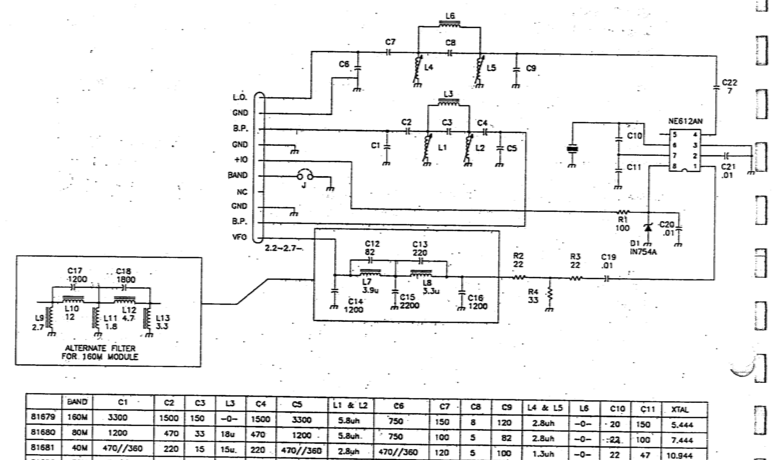
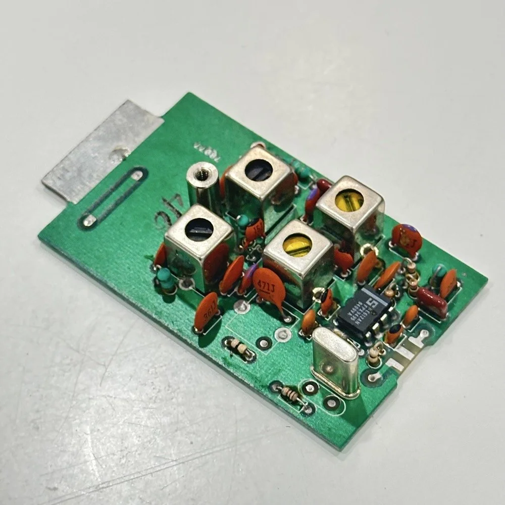
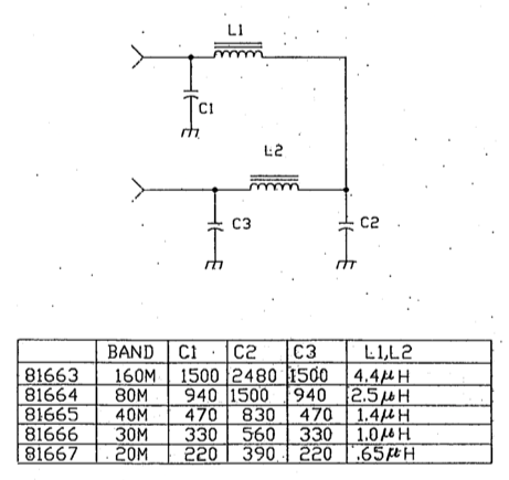
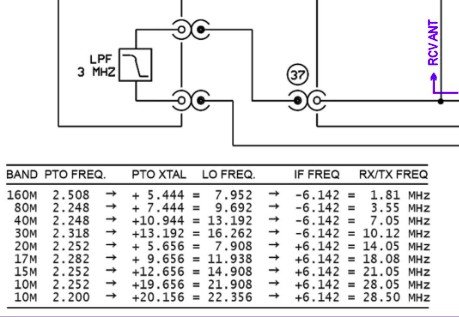
Above is the schematic and a photo of the board that goes with it showing the crystal that I couldn’t understand. This is what tells the radio what band it is on. Looks pretty straight forward at a glance, doesn’t it? Well look at that XTAL value at the end of the chart for 80 meters. Yeah, it takes a 7.444 mhz XTAL to get to the 80 meter band. So I figure the PTO is something like 3.0 mhz so it can get the first negative harmonic when mixed or something like that…nope…turns out I was totally wrong…
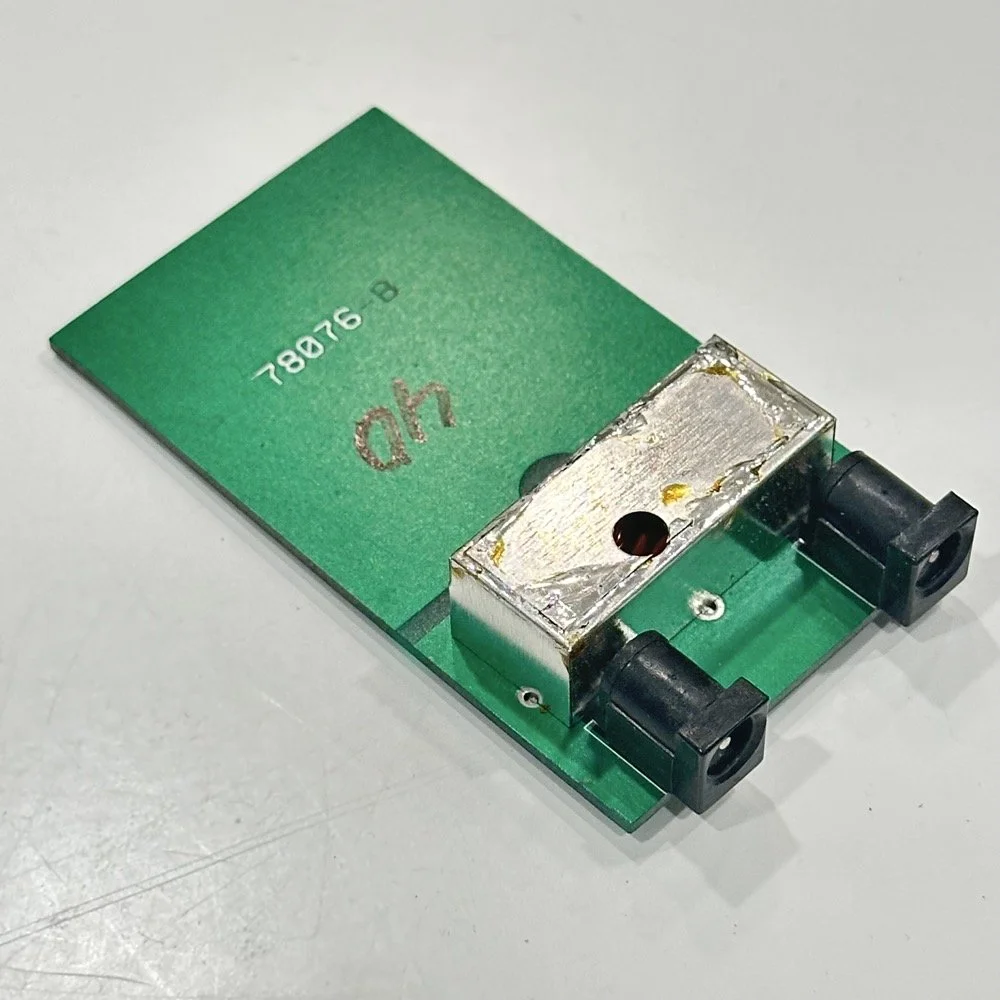
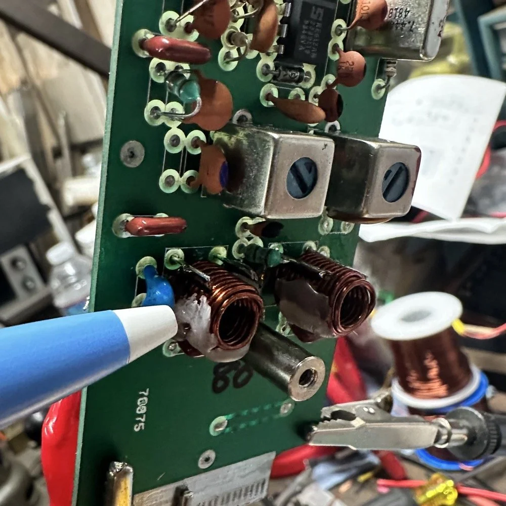
This is the other half of the band module. A classic low pass LC filter and that’s all. This is the output filter that the 50 power amp sends the RF to before it goes to the antenna. Below is what this part of the module looks like. These inductors and capacitors are shielded as they are delivering and filtering considerable power and could interfere with the small voltage levels on the other board that sits right beside it if they were not in the “can” or otherwise known as a ground shield. I don’t know why there is a hole in the shielding either as there is no adjustable parts inside the “can”. I chose this particular 80 meter band module for another reason as well. I have been inside this filter circuit before. When I acquired this module, the fellow I got it from told me it was dead and gave it to me. Turned out to be a broken lead on one of the inductors in this can. It took me a while to desolder this monstrosity to be able to access the parts inside of it. But persistence paid off as I was able to get it repaired and back in operation. I took a lead cut from a transistor and soldered it to the wire on the inductor and simply re-soldered it to the board and it came right back to life. So if you have a module that just stops transmitting all together, I recommend you pull the lid here and look at the inductors to see if one is broken free from the board, that might be all that is wrong with it. I also hot glued the toroids in place to help prevent this from happening again. Anyway, back to the project at hand…
I also looked inside several band modules to see what the differences were and I found some interesting things when I did. For starters, the 10 and 12 meter band modules both use the same circuit boards. They just leave out the second crystal and the switch parts for the second crystal and put a crystal in it for the 12 meter band only when configured for 12 meters. I guess, to be fair, I should have also figured out how the PTO worked as well then I could have figured out the reason for the odd crystal values, but here we are…
Another thing I found was that the engineers at Ten Tec used whatever circuit board blanks that they had on hand to build the band modules apparently. I say this because I found 10m circuit boards (the ones meant for two crystals and the switch) fleshed out with parts to make them into 40 m band modules. (Like the one in the photo above) They apparently just used whichever ones they had on hand at the time. Needless to say, what I thought was going to be simple was starting to turn into a pretty major endeavor.
You see it was starting to look pretty daunting since I didn’t understand what the reason for the odd frequency crystal was and that there were 4 tuned filters in each band module. Also the crystal value just didn’t make sense on the surface. The values were all over the place. I was about to throw in the towel calling it just too complicated, even though the parts count in a band module is really low…till I found two things. One was I looked up what the “555 timer” on the board actually was (Here is a hint, it aint no timer) and the other was NA5N’s website.
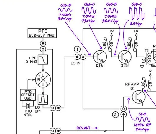
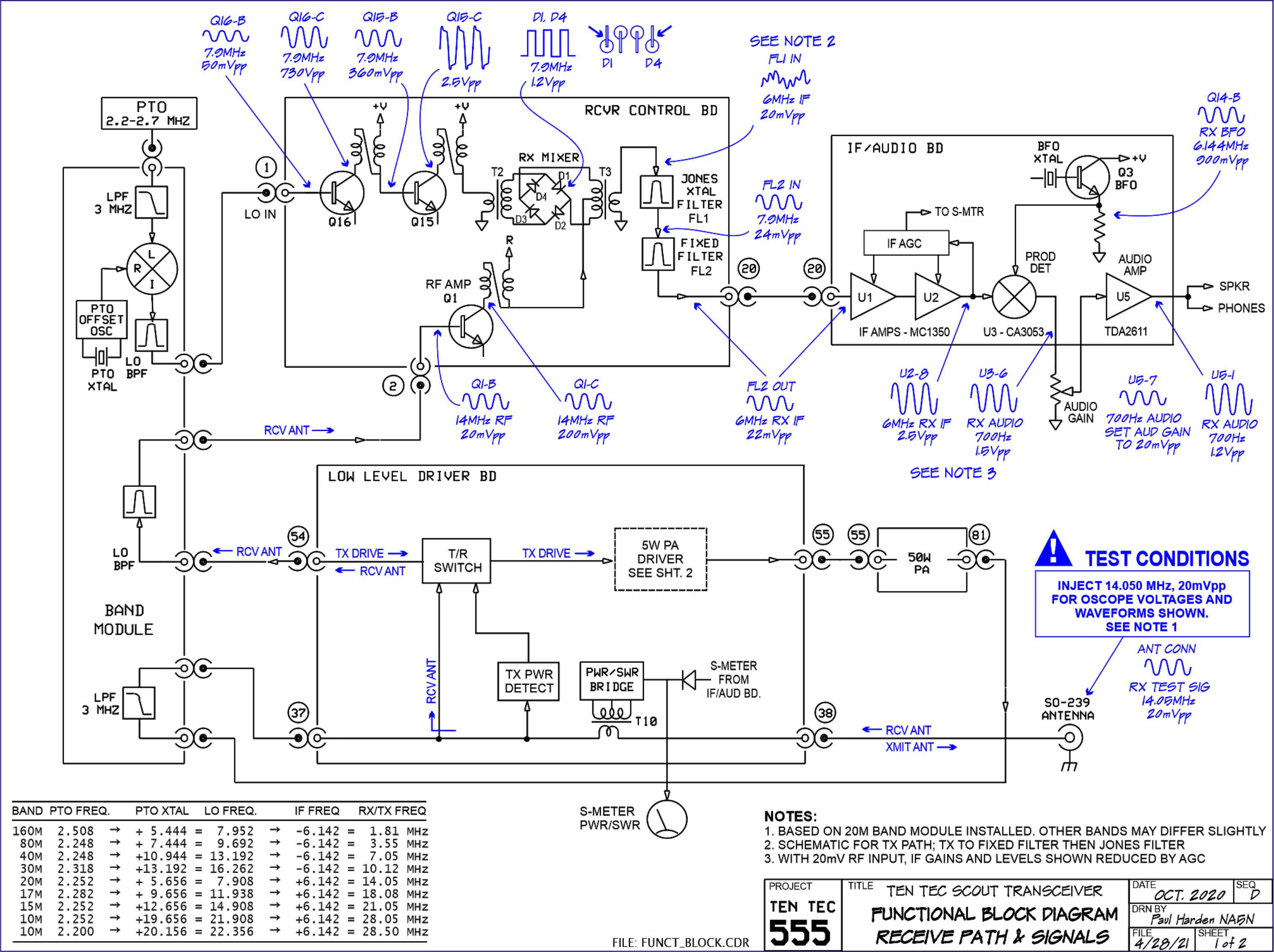
Excerpt from NA5N’s website showing the level of detail these drawings contain.
NA5N’s Scout 555 page is a figurative gold mine of information with just plain cash money piled on top of it, (just to drive this point home take a look at the piece above I grabbed for reference). I can not thank him enough for this information as without it I would not have been able to get this project working as quickly as I did. He also has some really interesting mods he has done to his own radio as well. If you want to perform his mods on your Scout, he gives you detailed information on what is done and literally how to do it…step by step almost. The greatest part of his page though is his info graphics he has built and placed there. These graphics show all sorts of information that the radio schematics leave out.
This and MUCH more is available on the NA5N website.
Things like the frequency path (pictured above) through the radio in a chart so you can understand how the engineers at Ten Tec arrived at each band frequency with these plug in modules and a PTO. Complete with oscilloscope test point and what you should be seeing at these points! Like I said, a gold mine buried in cash money…
Based on his chart I went through the band module and looked at the filters for the various circuits and decided (more like assumed based on the values of the parts) that I could simply re-tune an 80 meter module and “push” it up to 5.3305 mhz easily enough and without too much fuss…nothing could have been further from the truth.
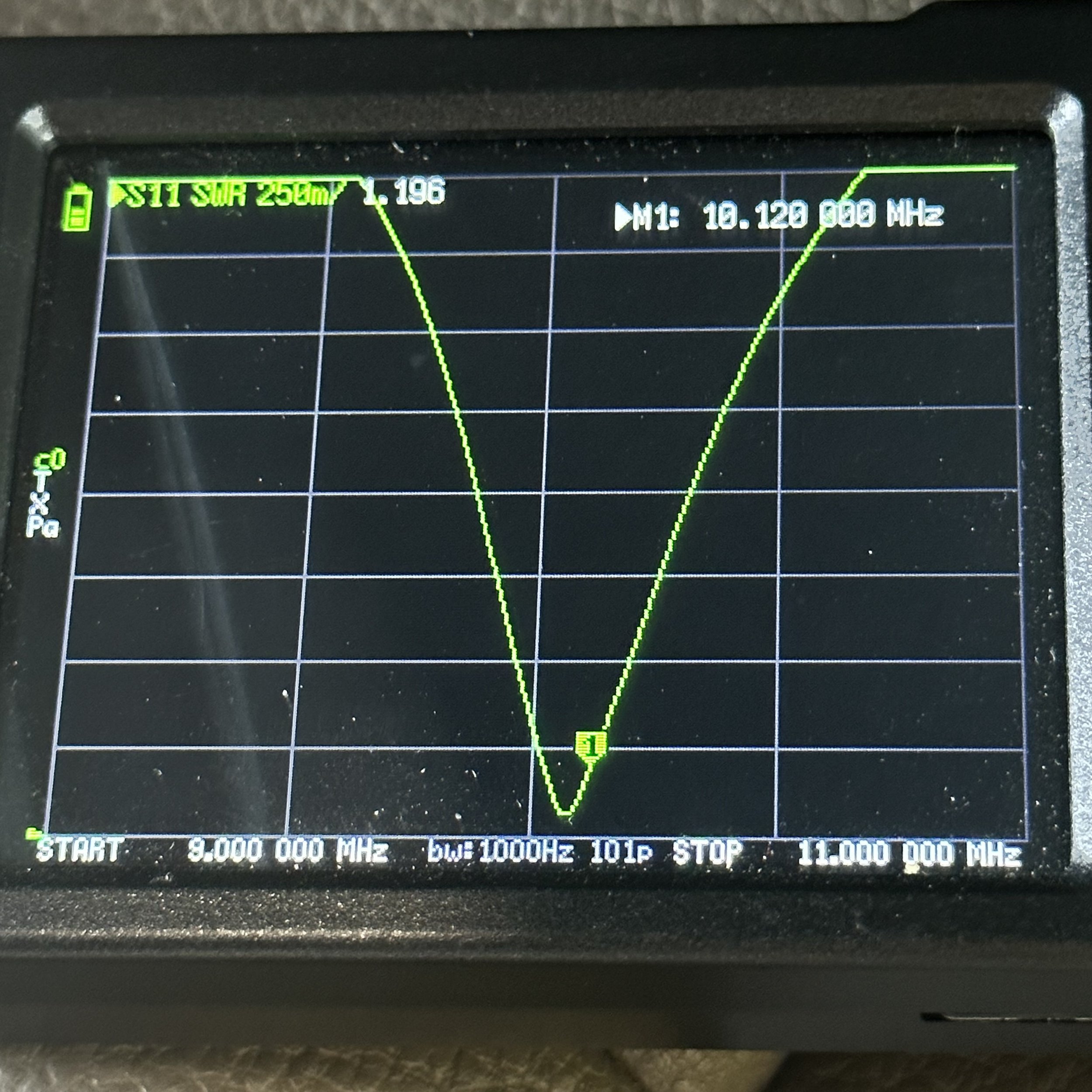
So I start tinkering with the filters and piping them through the nanoVNA into the s21 input so I can see the filter shape and all is well from what I can see. Turns out the low pass 80 meter band module filter cut off frequency was about 5.5 mhz or so to start the rolloff so the 60 meter band was still in the pass band! One down three to go! Next I figured out that the PTO is the same for every module since it is part of the radio and not in any of the modules so that filter also didn’t need any mods. This left two filters to re-tune, just so happens it is the two with the adjustable inductors in them. So I start with the LO BPF (Local Oscillator Band Pass Filter) that filters the signal passing through the radio from the antenna. Why they call it the same thing as the LO BPF that is in the output of the mixer chip is beyond me, but here we are… This didn’t go well as I was not able to get enough adjustment out of the inductor slugs to get the passband up to 5.350 mhz, shoot I couldn’t get it to tune up past 4.5mhz if memory serves me. It was far enough that I couldn’t get it work so I looked at what I had and decided to wind some air-core inductors to a lower value and see what I could do like that.
Well, to be honest, I don’t know how I was so successful here. Maybe it was the sheer audacity in the fact that I was woefully unskilled in building filters for HF or the mind boggling lack of knowledge of how filters work and how to make them, but I got it almost perfect on the first try! I made a couple different inductors by winding magnet wire on a 1/4-28 bolt (that’s a little over a 6mm bolt for the rest of the world) and the threads made getting good tight coil layers easy. I borrowed my friend’s LCR meter and measured them and blissfully declared them good to go at 2.0uH each. Did I mention this is a budget LCR meter and I have no way of knowing what the level of calibration is for this part of the meter? I also learned later that I can measure my inductors with a signal generator and a oscilloscope. Guess who now owns a signal generator as well as an oscilloscope...
Once wound and “measured” in the board they went! I then tinkered with the capacitors till the pass-band looked close to what I thought it should look like. (I had also learned from the wonderful world of youtube that I should see less than 1dB of loss in the pass-band and the 3dB cutoff point is where the filter technically is measured..typically.) As I mention in a bit, I used the wrong kind of capacitors (the little blue ones) to start with, although the module did work like this, I updated it with NPO capacitors ultimately as well.
I went down a long path of learning on this project, if you haven’t already noticed from the inserted comments in the story. I have very little formal training in Electrical Engineering, you see I went to a two year trade school back in the 1980s and basically got the “intro to electronics” that EE’s would get before learning things like matching the impedance of the filter to the next stage and to use temperature stabilized capacitors in RF filters so they don’t move the pass-band around when they get warm. NPO capacitors have become my best friends here…lol. A hint for my peeps who also didn’t study RF in college, look at the circuit board above that has the crystal on it. You will see the little capacitors on that board and some have little painted tops on them. This indicates NPO capacitors when the letter designation will not fit. I have now purchased a lifetime supply of these caps off of eBay…haha.
Anyway, now the pre-amp band-pass filter was functioning like it should. One to go…
Tune in for part two where we get into the problems I had to solve to get this module working and how well it works now that I have figured out my mistakes.
Continue reading the series:
- Part 1: Initial Conversion and Filter Design
- Part 2: Crystal Selection and Mixer Circuits
You can help support this website by using these Amazon Affiliate Links:
QRP/Portable Radios:
Antennas & Tuning:
CW Equipment:
Power & Accessories:
Organization & Transport:
BONUS ITEMS
73
WK4DS - David
Activated The Great Smokey Mountain National Forest
Here is the after action report where I finally activated a park in North Carolina. The Great Smokey Mountain National Park is a well used park in the POTA network, but it was one that I had not yet activated in my travels.

This particular area is called the Cataloochee valley and there is a heard of elk in this area that I like to try to photograph in the fall. Well since I was here, had a radio and the elk were not very close either…why not POTA?!? I decided to activate this park the night before and gave myself a decent little window of time to get it done in as well since I wasn’t sure how the elk would be doing… I had remembered from the last time that cell service was nonexistent here so I scheduled the activation on the POTA site the night before just as a precaution. This is a pro tip, if you even think you are not gonna have internet, go ahead and schedule the activation and pay close attention to the time as it is UTC time on the website and don’t do like I did and get the time off by several hours because you chose the wrong time zone… I did this on another activation and the results are as you think.

I found this spot and setup the truck-tenna (a hamstick on a receiver hitch mount I made) and the Ten Tec Argonaut 5 for this activation to just get on the air as I wasn’t sure how long I would have with band conditions being not great lately, so I wanted to stack the odds in my favor as much as possible ahead of time. Well it worked… as you will see later.

Here is a sign that lets you know just how unpredictable wild animals can be… Elk are VERY large creatures so it is prudent to heed this warning… I also thought it was interesting that the park rangers have to put out these signs at all… I guess getting a selfie is more important than getting killed by a bull elk…who knows?

This is what i found on this day though. The whole heard was just chillin in the edge of the treeline, so it wasn’t too heart stopping of an event to photograph them on this day. It was fun to just sit and peer at them through the camera for a while though. I have a video on my YouTube channel that showed a few more photos as well as talks about the rest of the trip some more as well.

Back to the activation though… I ran the coax into the cab as it was kind of cool this morning so I wanted to stay warm while I operated and just ran the cable through the window and left it down a little while I did since it wasn’t raining. This 15’ coax is just long enough to reach in this configuration too, which is nice.

Here we have the operating position today. I just sat the Argonaut in the seat, added a common mode chock and hooked up the HamGadgets cw keyer and my N3ZN tiny paddle and I got on the air. Power for the radio is pulled straight off of the truck batteries if I operate from this location as I have a power cable ran to the cab from the battery with power poles on it just for this. The arm rest makes for a decent desk, but it could be better. At some point I plan to make a table top that sits on the arm rest and goes forward to the shifter and even has a leg that sits on the console to support it as well. This will probably be covered with some sort of cloth so it wont be so rough on the arms and will allow me to spread out the notebook, pen and key a little more.

I could tell that the scheduled activation on the POTA site was working as I almost immediately got a pile up once I went live on the air and the RBN picked me up. It is night and day different as to what you get with and without the reverse beacon network picking you up. One QSO of note here is the Canadian call on the first page. We had quite the QSO and spent a few minutes chatting about things before I got back to the activation and went to work on that. I am not one to shy away from a ragchew even though I wanted to work a bunch of contacts too, it is all about talking on the radio so I love all of it.


I had a steady stream of calls come in for a little over an hour. that is awesome! I love it when I am able to catch what I think is all the QSOs that are calling. The band was really strong today too as I was only using 15 watts and was able to get really good signal reports back from most everyone. It was a really stable day as well as it can also be seen in the log that the signal reports were steady and not sinusoidal. Sixty three contacts later I called QRT to go get some lunch and fuel for the truck before heading on to Ashville for the afternoon. If you are interested in the rest of the trip, I have a YouTube channel where I talk about the photography aspect more. Thanks for coming along and until next time, go get on the air!
72
WK4DS
Counterpoise testing during a POTA Activation
Today involved some experimentation as well as a POTA activation. I tested some changes to the radials I use on my hamstick system out of curiosity and came away with some interesting results. Read on to see the AAR and the results of this test.

Today was supposed to be a quick little activation and then I was going to do a few other things, but plans are made to be changed from what I can tell as the bands were doing well for me and I stayed longer than I planned. But then the sun can bring that full circle as you will see below.

The operating position today shown above, was on top of the hill at the frisbee golf course and on the bed cover of the truck. Turns out that was somewhat of a bad idea. It just got hotter as the day progressed and the sun quickly came over the door I was using to shade me. This is what ultimately caused me to go QRT when I did as I was having a decent run on 20 meters at the time. It was just plain hot, with the sun seemingly cooking my right ear while I was working ops. I did enjoy working several ops today I have seen in my log before plus some that I have not. I even got a Canadian which is always nice.

This is probably the best image of my 40m hamstick and mount I have ever gotten. With the sun in the right spot, the whole antenna lit up well enough for the camera to get it. The setup is not actually mobile as it requires a counter poise to get it to work it’s best, but wow… it worked really well today, especially well today actually for some reason. I can hear surprisingly well on these tiny HF antennas too. I own three different brands of hamsticks (covering 40, 30, 20, 17 and 15) and can not tell a difference in any of them as far as how well they work. They all just work really well.

These two photos tell a story about what was happening at the location today on 30 meters. When people talk about having RF noise at a location, this is what it looks like on a radio that doesn’t have a waterfall display. The photo above is what the noise floor looked like when the RF noise was not present and the bottom image is what it looked like when it started up. It also was not constant, but appeared to by cyclic in nature as it would spool up and would just be some sort of hash for about 20 seconds and then it would just go away for about 30 seconds maybe longer. I would be able to work one contact and then it would come back and if the hunters were not transmitting with an S9 signal, I couldn’t hear them. This is really frustrating and is one of the reasons I don’t activate 30 meters more than I do. But so it life and how much fun would it be if we never had problems to solve? It would get pretty boring pretty fast… Even with this RF hash coming in and out, I was still able to get 9 calls in the log on 30 meters today so I count that as a win anyway.

The next thing I want to share about today has to do with the antenna system I was using. I have made tuned radials for all of my hamstick except the 15 meter unit (I have not deployed it yet, but soon I will.) I went to a lot of trouble to tune these radials too, with a ton of time at home working on this. Well, it turns out that I didn’t need to do that for the 30 meter hamstick at all. I deployed my nanoVNA today and did some measurements on the hamsticks to confirm nothing has changed with them and figured out something just out of curiosity. Seems that the radials for 40 & 20 meters work just fine on 30 meters too. This means one set of radials for all three of those hamsticks. Next outing I will take the 17 and 15 meter hamsticks and tune them up and see if the same radials will work on them too…fingers crossed. I am always looking for ways to simplify my station setup and the radials has been one of the slowest things to deploy of all the gear for POTA with the hamsticks. So if I can get it down to just the two radials and not having to remember the color codes for them and such I will count that as another win in my book.

The above photo shows that the antenna is fine on the 20 meter CW section, even though it is technically low on the best part of the chart, it is only 1.188:1 where I normally work on the 20 meter band. Well, knowing that, below is what it looks like on 30 meters with the 40/20 meter radials instead of the tuned radials I made up for just for the 30 meter band. Pretty crazy huh? Looks almost identical to the 20 meter chart and even almost matches the 20 meter SWR value. I was blown away by how good this turned out and to think I have never even tried it before today… Another thing I noticed about hamsticks in general is that they act like bandpass filters across the HF spectrum, I did open up the range on the nanoVNA and it does have other nulls IN THE VHF SPACE, but each hamstick has ONLY ONE spot they are resonant at in the 0 - 30mhz spectrum. No multiple harmonics like the EFHW, just one really deep SWR null is all you get. So plan accordingly, but to be honest, it works really well so I am not going to complain. I think this might actually work as a band pass filter but have not had the chance to test it yet. Maybe I will set this up at winter field day and see what it sounds like there. That should do it.
Here is the log from this activation and the signal reports look good for a mismatched antenna on the trailer hitch of my truck. I was using 15 watts though so that might have helped some. I have been sending with more power lately to just play with the Argonaut to see how hot the heat sink gets at various power levels and on CW it barely gets warm at all with 15 watts of RF so I am really happy with that. I am doing this test since i changes the fan a while back to reduce the fan noise as the factory fan is quite loud. I have a blog post showing what I did with this if you are interested in that.


All in all I learned something new and had a great activation at the same time. So till next time go get your radio out and make some contacts on it!
Testing a new antenna AND CW key during a POTA activation!
I decided to pack up the Argonaut 5 and go activate Cloudland Canyon today to get some much needed air time and wanted to try out my new POTA key that I picked up at the 2023 Hamfest in Huntsville a little while back (actually you will be reading this in the future as I picked up the key last weekend but so is the life of a blog post) So follow along and look at what I found out today while making a few contacts from K-2169.
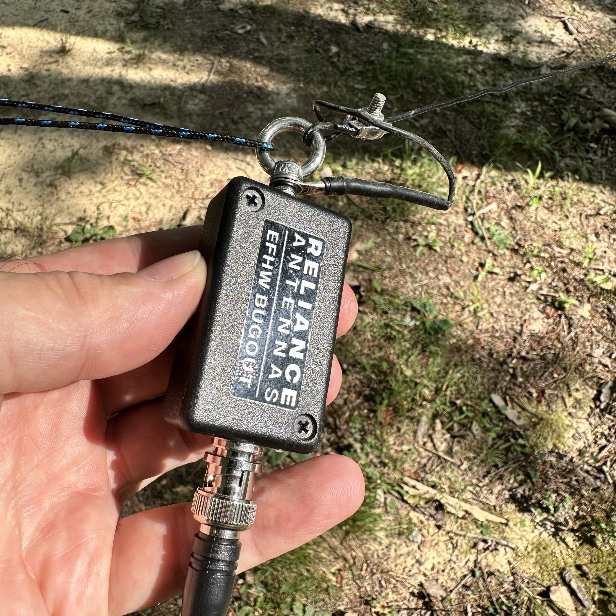
I also decided to do some testing of the Reliance Antenna Bugout 40 EFHW I had bought from N3VAN who was making them and selling them on the QRZ forums. The antenna looks really good with lots of attention to detail in the construction. I have never used an antenna that doesn’t have radials or a formal counterpoise at all. This one uses the coax shield as the counterpoise so, in theory, you don’t need a counterpoise at all. (Come to find out, you can bend the rules of EFHW antennas if you do add a counterpoise) I strung it up in the air between two trees out near the bluff at the park. This may have doped my results, but I am doing a test anyway so why not, right? The far end is about 30’ in the air. The near end is about 12’ up to the transformer and I dropped a 15’ piece of coax down to the radio. Done. Well, so I thought at least.
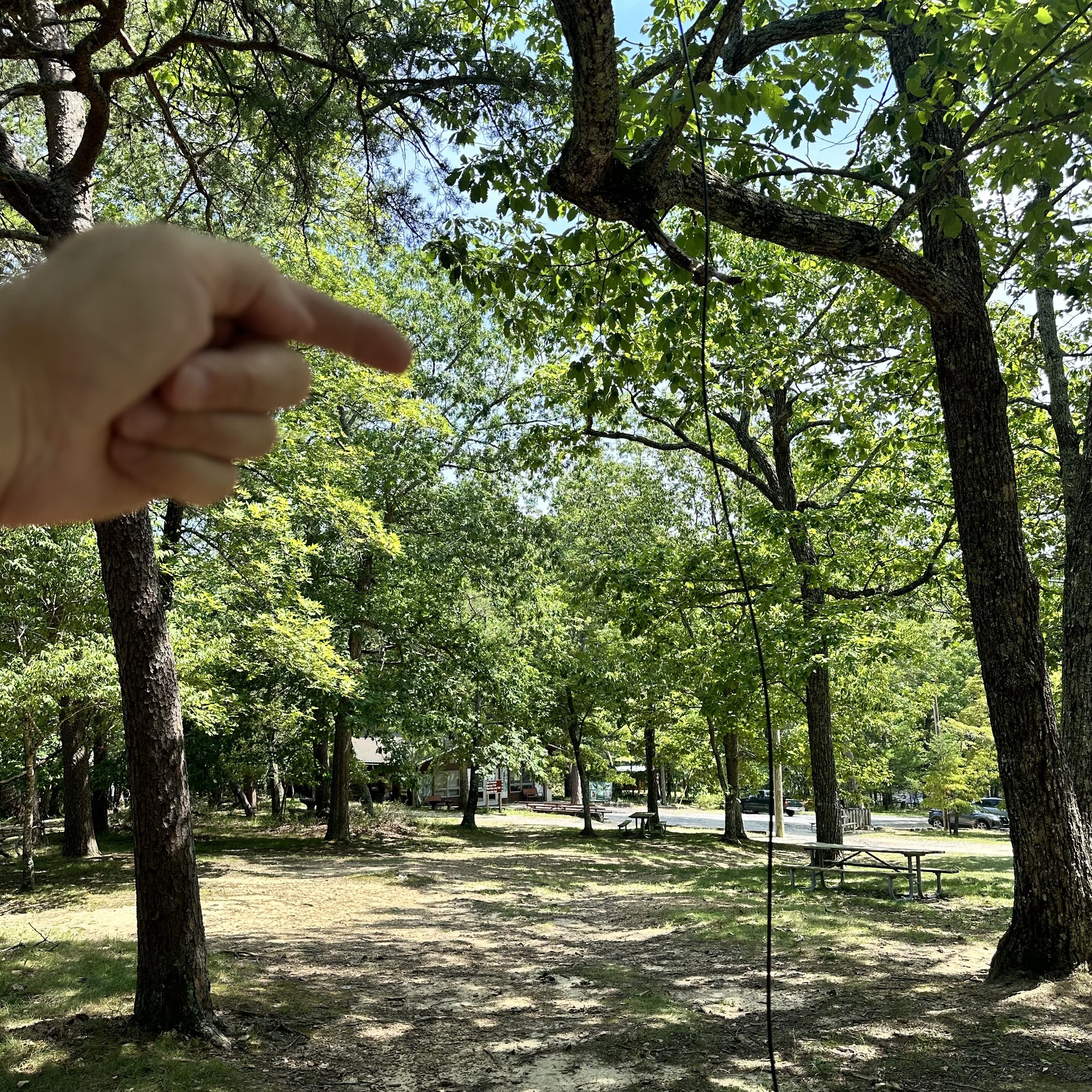
The far end is way up in this bright green tree behind my hand in the back ground. I am pointing to the end of the wire location in the tree.
Once I got the antenna up in the trees, I wanted to see what the plot looked like on the nanoVNA so I plugged it all in and this is what I got. The antenna is technically slightly long and is a little below optimal frequency on this day and rigged like this. I am not going to trim it at this point as I want to see what it does in other kinds of conditions like the winter and maybe right after a rain when it is still wet or maybe where it is set up over night and is soaked with dew. Even though it was off frequency a little in the configuration I had it in, the SWR was well within safe limits for operating any transceiver. I didn’t have a 2:1 SWR at any point when I was testing a particular band and that if fine with me if I don’t have to carry a tuner with me. There was a side bonus to this setup too, for some reason with the whole antenna elevated like I had it, it was giving me a wide coverage (read that as a low q) in the bottom of the 10 meter band. So low in fact, that it was within usable range even on 12 meters without needing any sort of a tuner! That is 40,20,15,12 & 10 in one antenna with zero mods needed. That is winning in my book.

This was the plot without anything other than the 15’ coax going to the common mode choke.
Now get this, I added a radial to the system, but in an unusual location. I put it on the end of the coax on the connector next to the common mode choke right next to the radio and just stretched it out over the ground. This length of wire was 9.5’ in length and when I did this, the plot changed a lot. I lost the 12 meter dip but picked up a much broader area between 20 and 15 meters to the point that 17 meters was below 2:1 SWR at this point. This means that if I add this simple piece of wire I now have a “no tuner needed” antenna that covers 6 bands! Almost everything is usable…sans 30 meters, so I am really happy with this antenna. The next time I set it up will be to test it as a sloper like it would be used if it is a portable setup and I had only one tree to rig it to. Then we will plot it again and see what I come up with. I am curious to see if the frequency of the dips changes with the relation of the end of the antenna to the ground. I dont think it will but RF is a fickle girl…lol.

This plot is the aforementioned setup plus a 9.5’ length of wire tied to the coax connecter at the common mode choke.

This much wire is all that I needed to gain access to 17 meters without having to carry an antenna tuner with me, this is very liberating to be honest. Just adding a small radial to the system makes this super easy to use. The Reliance Antennas 40m Bugout EFHW comes with a winder to store in on as well as a carabiner clip to connect the far end to the cord. The transformer end has an eye bolt that works well for a hoist point to raise the other end of the antenna.

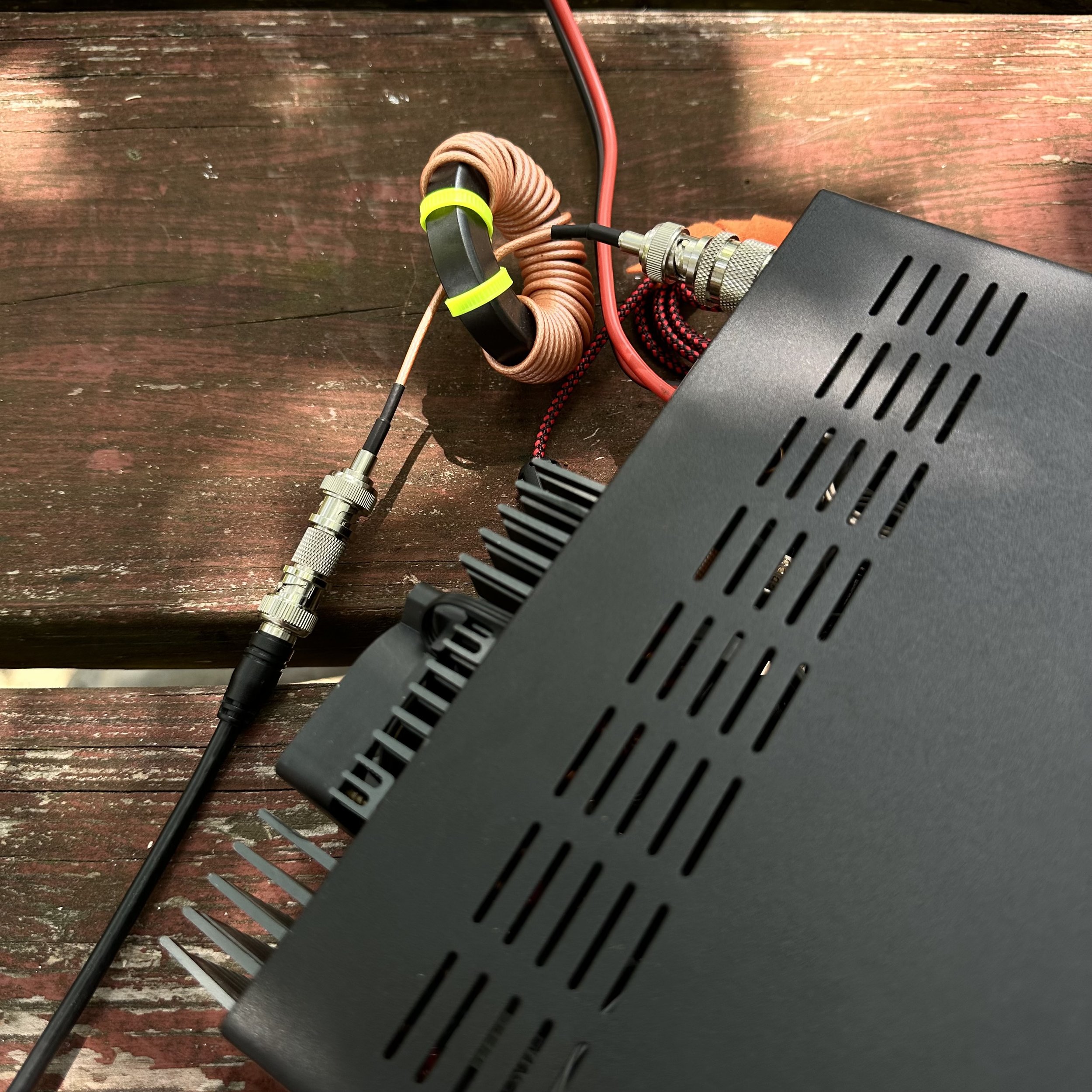
I next setup the Ten Tec Argonaut 5 radio on the table and connected all the stuff to make it work. Once it was powered up and ready, I plugged in the star of the show, my new N3ZN CW Key. He builds some really nice keys and I have walked by his table at several hamfests recently and today I decided that it was time to give one a whirl as they say. So I chose the smallest one he had at the show since I wanted it for POTA activations. The plan is to keep it in the Argonaut “GO BOX” that I built last year. It took me two trips to the field to learn to use it properly too. Since it is so small, if you have a heavy hand when you send it will move around a lot on you. The trick is to set the action light enough that you just have to touch the paddles to send the code, this way it is a light operation and the key stays put on the table like it should. These keys come with the cord hardwired to them so you cant buy a simple aux cable and plug it into the key, but it didn’t cause me any trouble so I don’t mind it. The installed cable is high quality and I have no doubt that it will last a very long time.

Once the antenna was squared away and I had my 17m “element” nearby, I was ready to crank up the radio. The new key plugged into the keyer I recently acquired from eBay and we are off to the races! Or so I thought as it turned out that KJ4BAD happened to be walking by and stopped in to see if I was doing POTA and we had a great chat for about 10 minutes or so about all things radio. I always enjoy running into other hams while out at a park.

I really like the Ten Tec Argonaut 5 radio, it has almost all of the CW functions that I use are on the surface. There is a could of things that you hit a button and then make the adjustments and you are good to go. The other thing that is great about this radio is that it has 20 watts of transmitter power. This is awesome when the bands are not as good as they were back in the winter. Also the DSP filtering works surprisingly well. It is also really good with other modes, but I just use it for CW… I might make a cable at some point to put the key into the front socket instead so it is simpler to connect the key. You see the mic key will key the radio so that means my little memory keyer will work in that socket. Who knows when I will do that though…


After we finished chatting I settled in for some POTA therapy and dialed around a little to find 15 was open with a bunch of stations on the air. I setup and start calling and you can see in the log that I only made two contacts before giving up and moving to 17 meters where I usually make several contacts but today I only netted one. Things were looking pretty dismal till I went to 20 meters. Once on 20 things turned around for me. I fairly quickly got the activation and proved out all the gear I had brought that day.
This photo shows where I would place the extra radial on the Coax connector. The coupling between the common mode choke and the feedline made for an easy spot to add it. I simply stripped the wire back a little and twisted the wire over this point. Simple as that. The easiest mod I have ever done to tune my antenna to another band in the history of ever.

This was the view I had today while operating, this is why I like POTA over other activities. The view is epic. So there you have it. My POTA “test and tune” trip in a simple blog post. Until next time, 72.
de WK4DS
2023 Huntsville Hamfest from the view of a vendor this time!!!
Man time flies! It has already been a year since me and Trey had come over and bought all those military surplus cases and stuff! I cant understand how that has happened…
Anyway, I signed up for a table in the “bone yard” which is indoors at Huntsville, which is nice since it means it is out of the direct sun in August and has air conditioning. Well Trey arrives the day of the event and I already have my stuff int he truck, we just load a couple things he is bringing and we are off.
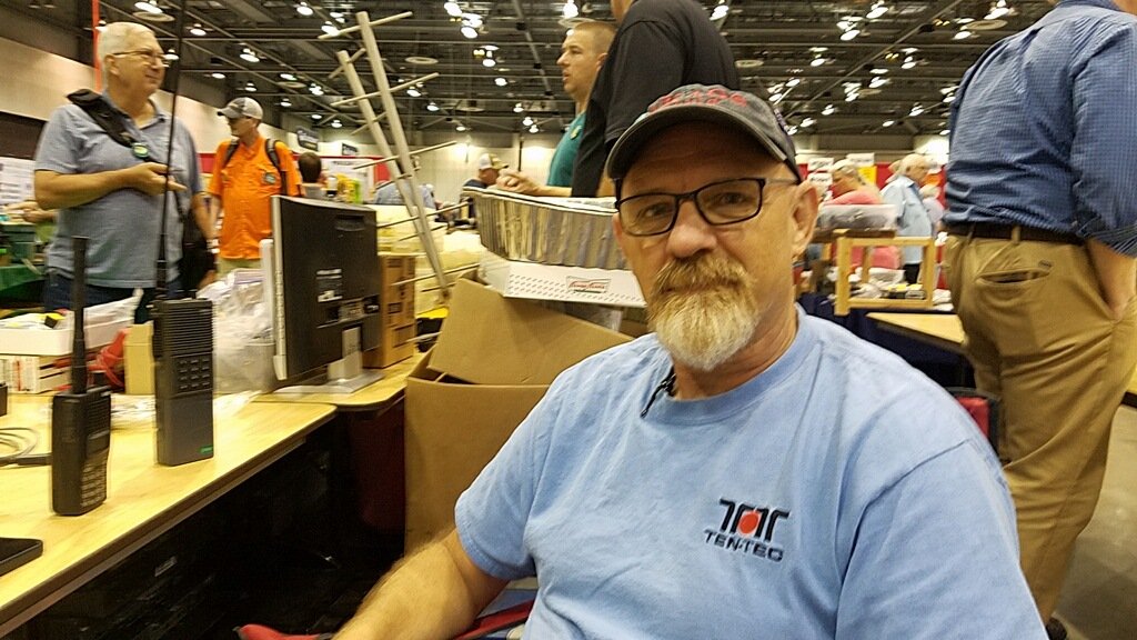
Side notes: Check out the vintage Ten Tec t-shirt I only get out for this and sometimes Field Day, I am probably the only person alive who still has one. I am also monitoring two ham bands here, our 2 meter simplex frequency and our 1.25 meter simplex frequency, We used both over the course of the day to make contact with friends. Back to the story already in progress…
We get to the convention center right on time and find a huge line of cars waiting to get into the show area. Once we work our way through the line we figure out these people are parking in the underground parking lot and we need to go to the back to unload the truck, well we get out of line, unload the truck and setup in short order. I can tell already it is going to be a good show for me when I can’t even get the truck parked before Trey (who went with the stuff to the table) is already being pummeled by dealers wanting to buy my stuff! This is a good sign!
By the time this photo was taken, the Icom IC 705 and tuner were sold. It literally lasted 5 minutes. this is good as the proceeds from the sale of this radio went to purchase the sBitx radio that I want for POTA instead. I had also already sold one of the two power supplies I took over as well. Common items seem to have went really fast to be honest.

Here, Trey (KG4WBI) Is getting settled in for the long arduous day of minding the table. Also, at this point I still had the Elecraft K1 pictured here as well. More on this radio later.

Once the doors opened, it was a free for all till about lunch time. It was REALLY crowded with so many people that it was hard to imagine the total number of participants. Everybody seemed to have a radio, even the little kids!

Things moved off of the table steadily all morning though and I had high hopes that I would actually achieve my goal of not taking any of it home with me! Each little item, one by one, would get picked up and bought by some enterprising person looking for the find of the day. I was happy to help them too.

After lunch I made my way over to the POTA table and grabbed a photo for the blog, they were pretty busy so I didn’t bother them with my shenanigans but left them to inform the youth about the wonders of ham radio. While out on my stroll I did check on a couple of items I was looking for and stopped to play with the N3ZN keys for a minute as they are SWEEEEET! Then it was back to the grind of tending “shop”…

I continued to see the stuff I didn’t use goto new homes one at a time till I was down to the K1, the Ten Tec 238 tuner and the Comet Antenna Analyzer. Then the strangest thing happened. I had to goto the bathroom. Well, that wasnt really all that odd, but what was happening at the table was. Turns out Josh from Ham Radio Crash Course had sent out scouts looking for a K1 or a K2 and they found mine and told him. He was livestreaming the event too! Well, he finds the table and makes his way over to it to find Trey minding the booth in my absence. You can actually watch his stream and see the whole thing transpire, just fast forward to about the 18 minute mark to see where it all starts.

A little back story here. I love the little K1, it was a favorite of mine for many years and I have used it off and on for that time. I just took a long hard look at the gear in the shack and realized the K1 sits on a shelf WAY more than not and I needed it to goto a good home where it would see more air time. So with a little sadness, I packed it up to goto the hamfest to find a new home. I get attached to things like this way to much and this is an exercise in decluttering my life, I wanted to move out a ton of gear and not just throw it away or such but turn it into something I would use instead. The K1 is just a plain fun radio to use, hence the pain in seeing it leave. I believe Josh will do a wonderful job at this and look forward to seeing the little K1 on his youtube channel soon.
It was great interacting with him and getting to chat for a minute, he took it straight way over to the test bench and had them check it for operation and he was happy it worked as advertised, All of this is also in the livestream…lol.

Then I had one more trek around a little to pick up a few items I have been looking for and actually found. I got a coax and some connectors from the Wire Man, I got the drop-in desk charger for my old Icom HT I have been using lately and it even came with a working radio! So now I have two!!! HAHA, why did I come to the hamfest again??? Then I bought a cable from another cable builder, ABR Industries, and I must say they look really good, I wanted a new coax for my POTA work and he builds his with common mode chokes built into the cable, that is really nice and i am looking forward to testing this cable on the nanoVNA to see how it compares to my homebrew chokes I made.
Then the finale of the day came when I went back over to N3ZN’s booth and talked to him about a small POTA key. The next thing I know, I bought one!

This key is tiny, at about 1.5” by 1.5”, it will be an awesome POTA key. I am going to look into how I plan to use it and expect there to be blog posts coming soon about it. I also got to talk to the man himself while he filed out my ticket on it and he is an amazing guy, I count it as a blessing to have met him. Hopefully we will cross paths again soon. If I get the chance I want to share with him my keys I built back in the day, we talked for a while and he is one of the few people that can actually appreciate the work that went into making them.

In closing I wanted to share a photo of my current dream rig, the Elecraft K4 with or without the amplifier, I just want the radio to be honest. At some point I will upgrade from the aging Ten Tec radios in my shack and this is probably what will replace them. I love everything about this radio and quietly take a peek at it when I am at the hamfest, but for now, there is POTA to do and contacts to make with the gear I have!
PS: All I brought home was the antenna analyzer and the Ten Tec tuner, both of which I dont mind holding on to for a while longer…
73
WK4DS-David
Ten Tec Argonaut 5 goes to the park and then gets a new fan!
I love this radio, it works so well and is really easy to use with minimal menu settings. Then again I love all TenTec radios and have an unhealthy addiction to the brand…lol. Is it really that bad of a problem? I bought this one “for field use”, you know… like Field Day in June or POTA, but I have found things about it that keep me reaching for other radios most of the time. Let’s take a look at some of these short comings for a field radio that I like to use while doing an activation.

So I get this radio out much less for a couple of reasons… The main one is that it doesn’t have a CW keyer memories built in like the ICOM IC-705 and the Penntek TR-35 have in them. This is a big deal if you plan to activate for more than an hour or so as calling cq over and over manually can be strenuous to say the least with time. You see the keyer does something for me other than relieve me from having to pound out the CQ all the time, it BUYS me time. I am able to make log notes and fill in missing parts of the log while it is happily sending the CQ for me. This is a huge help after a quick string of QSOs and I am getting the times written down along with my usual log notes I like to make.
Quick rabbit to chase here… There is a few notable call signs for me on this page. K9IS is my first Hunter to get to 50 QSOs with me and KJ7DT has been showing up in my log more frequently lately too. The other call is the Canadian, just because he is DX…lol. Always cool to have those DX callsigns in the logbook. Now back to your regularly scheduled chat about the radio.
The next reason I don’t normally grab this radio is that it is fairly large compared to the other radios too. When I am operating in the truck, space is a valuable commodity and I am not able to spread all the gear around easily, if you will notice in the above photo I actually have the Argonaut balanced on my camera bag so it wont be in the way of logging… This actually worked out pretty well though and I think I will come up with something for the other radios to sit in the same area in the future, it was really convenient having the whole surface for my book and key.
The next reason is that the fan is crazy loud and runs non-stop even when I have it turned down to 5 watts for my QRP ops.

A little about the activation today is also in order. I went to K-2169 (my local park) and went to my quiet place at the top of the hill. As you can see, I had the place to myself as usual.

So I get parked, then start assembling the antenna and getting the coax into the cab of the truck when I notice that the cable adapter I have on the base of the antenna is loose, I am not sure how long it has been loose, but it was pretty loose today, to the point the BNC connector spun when I went to install it. This is how I found it was loose. Point here is check those screw together connections from time to time. They work loose too. The one on the back of the radio was loose too… which I thought was odd since I have only used it a couple of times so far.

Although today I didn’t need them, the BNC converter is a nice adapter to have in your kit. I could have used regular PL=259 connectors today, but I had forgot that the antenna and the radio both use them so I just used the same cable I use for the other radios and it worked great.
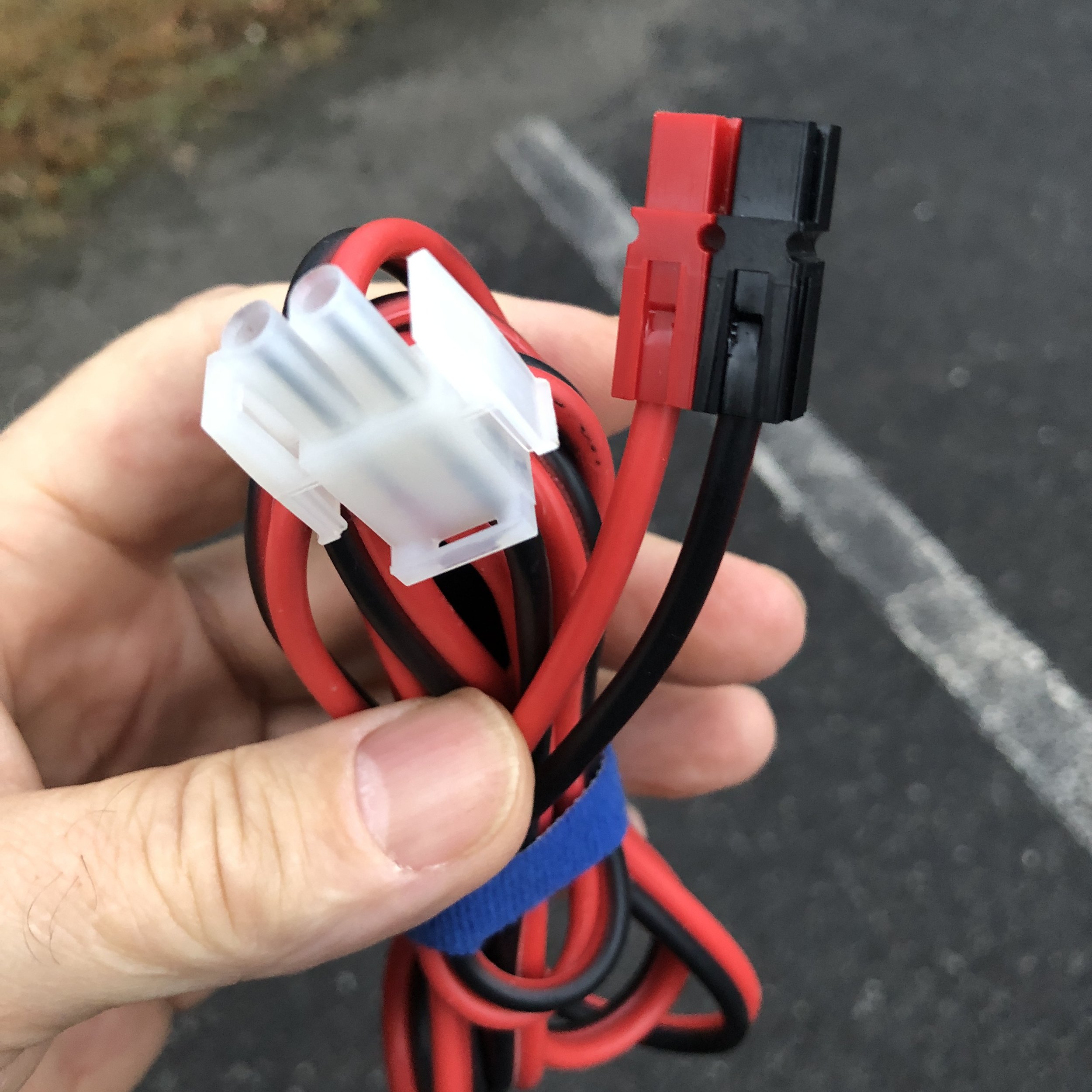
Another thing I have done is converted the power cable to use power-poles so I can plug it into any power source I use, which now also includes the power port in the truck too. I feel this is a worthwhile thing to do if you plan to work field ops a lot, standardization of the power connectors just makes sense.
I bought this case at the Huntsville Hamefest from Gigaparts and it is for some sort of military radio, but with a little cutting here and there and a little foam here and there it now houses the Argonaut 5 and a MFJ manual tuner as well as a wire antenna and some other miscellaneous items


Me and Roger (KG4WBI) have this obsession of printing out and binding all the owners manuals for all our radios. So I keep this one in the case with the radio and it was needed on this outing to see how to set a couple of menu items I had forgotten about.

Now for the Argonaut 5 Radio Fan…
The fan on this radio is just plain loud, that is the only way you can say it. It is also wired to run non-stop for some reason. This is also a pretty large current drain for no real reason at all other than to make absolutely certain the finals don’t get too hot… At some later point, I plan to make a small thermal sensing circuit that will fire a relay to cycle the fan instead of it just running all the time. but first things first, I am changing the fan itself with one of the low noise fans that another op from a TenTec group shared and it worked really well for them. I downloaded a sound meter app for my phone to see if it was measurable and have the two meter readings to see for myself. Ignore the AVG and MAX values, I watched the meter for a few minutes and did a screen capture of what was really going on to get a more representative number. 65 seems pretty low, but when you are listening for signals near the noise floor, every dB matters so the new fan comes in at 45(44.9 is what I captured in the screenshot and this was a pretty good average from what I watched on the meter.) Now also remember this is an iPhone app and not a legit sound meter, but it does give us something to look at for reference. If it is right, which is possible, then this is a 20dB difference. This is huge as decibels are logarithmic in nature and not linear, this is equal to 100 times quieter! That is awesome and totally worth the effort! To the ear, this new fan is dead silent, I didn’t think it was even running when I turned the radio on actually. So I am really pleased with how this mod turned out, the radio has one less detriment to keep me from using it at parks!

Old fan measured right at the back of the radio.

New fan measured in the same place as the old fan, that is a 20dB change!!!!

This was the ham shack with the Argonaut turned off for reference.

Orderd this little guy from amazon and had it in a couple of days.
This fan is literally a plug-n-play replacement for the factory fan in the radio. I literally removed the case screws, the fan screws, one wire tie on the wiring harness and unplugged the fan. It was the easiest mod I have ever done to a radio…ever.

Something of note, this new fan is thicker and the old screws would not work in my application, but I had a couple of screws in the junk drawer that were about 1/4” longer that worked great so I am back in the game!

The fan connector is a standard computer fan plug so it doesn’t need anything special at all. This is refreshing as it seems everybody wants to use proprietary connectors these days for some reason.

All in all, this has turned out to be a great little excursion in more than one way. I got the Argonaut on the air and I also got the fan upgraded afterwards too. I really like the ergonomics of the little machine so I will see how I can fit it into my regular activations and use it more now. Do you have a radio that you love, but just dont use because of some little issue? Let’s hear what it is and see if I am the only guy that does this.
72
David
WK4DS
Why do I want to buy so many ham radios???
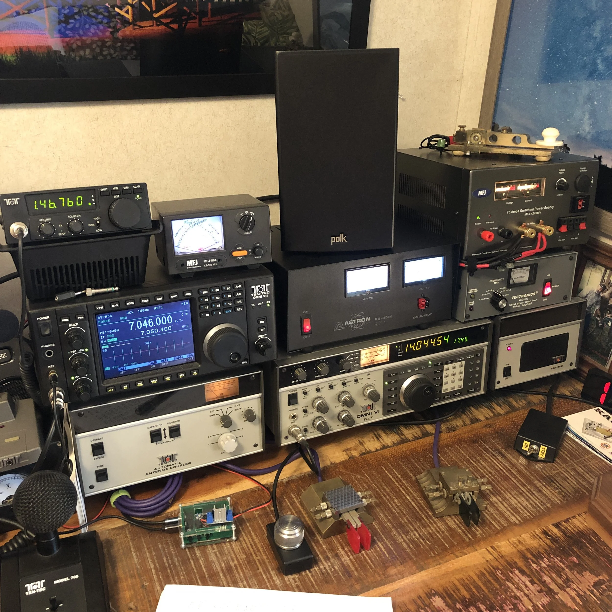
My main base station. The Omni 6+ is connected to the 500 watt amplifier and the Omni 7 is “barefoot”.
I find myself wanting every radio I see and with a short look through the bios of some ham operators on QRZ.com I am not alone in this.
What is it with this obsession wiht collecting radio gear that us hams must endure? I mean they literally all do the exact same thing…all of them. Yet we want multiples of these radios anyway.
Now, I understand having a base rig that stays at home and can be integrated into several things and it is not simple to break down for portable operations, and also having a radio that can do specific jobs like SOTA or POTA or ARRL Field Day.
This makes sense but why do we want to have two base rigs or three or five or 10 as well as three or four portable radios for POTA as well as mobile radios stacked to the ceiling and we can only use one at a time. LOL.
You see, I am that guy. I have a base station that has two complete radios in it that share an antenna and I also have FOUR, yes FOUR, POTA rigs currently! Four, really? A TenTec Argonaut 5, an ICOM IC-705, an Elecraft K1, and a Penntek TR-35 and I love them all… I just don’t understand the human brain sometimes, why do I want so many radios? I realized this yesterday when the Penntek TR-45L was launched, I REALLY like this new radio and found myself wanting one really bad, but then I stopped and let reason talk to me for a minute and realized that my current radios ALL DO THE EXACT SAME THING!!! To add to the problem, one of the radios is the Penntek TR-35 for crying out loud!!!! LOL!!! Compound that with the fact that I have yet to use it for a field activation and my wanting the new radio is just lunacy… So how do I combat this? Well, the first thing is to get out these radios and take a long hard look at them and decide if I really want to own these radios or the new one. I personally have also set a limit on the quantity of radios I will own as well…apparently there is an exemption for POTA rigs…but I digress. Another thing I have implemented as of late is a rule of balance. This is where I have to remove something if I want to add something. By doing this I keep the stack a little more reasonable and I can recoup some of the money needed for the new radio from the sale of the old one I am letting go to make room.

The POTA rigs are starting to pile up!
Some will say it is because each radio has a feel to it and some radios have character to them and to this I say they are right! I also understand that once you find the radio that you like the most, keep it and the second most favorite as well and then get rid of the rest of them! LOL. Are they really bringing you joy just sitting either on a shelf or worse…in a box under the bed!!!
You see having multiple radios like me doesn’t benefit the amateur operator in any way other than collecting. If you enjoy collecting radios then by all means, buy as many as you want, but remember if you are not collecting radios then what is the point of buying so many? Of course this is my opinion and this is not a rule in any way, shape, or form, but I do have reason in the thought process. What else could we buy with the money we spent on all of these radios had we not bought them?
I also dabble in the hobby of photography and that hobby is no different from Amateur Radio in that the most appealing or “sexy “part of the system is the central piece which is the radio here and in photography it is the camera body. These are universally wanted by the users of each hobby respectively. Photographers will have gear acquisition syndrome (G.A.S.) and make joking videos about it on YouTube because it is such a problem. It is a real thing as companies spend dumptruck loads of money on targeted marketing to tell you that you need to upgrade to the newest widget or risk falling behind in technology. That is how they get you!!! LOL!!! They prey on your GAS problem!!!
So how do we solve for this? I honesty don’t have the universal answer. For me it took about 40 years of buying too much stuff for a hobby and as you see above with the stack of POTA rigs, I am not there yet… I do know that I am starting to recognize it though and I am working towards scaling back the stack of cases so that I have room for other things in my shack. I hope this helps some of you out there to realize the same thing I realized and that you can do other things instead of buying the newest radio. Anyway, now that we have all did some self reflection, reach over and turn on that radio next to you and see who you can find on it.
73
David - WK4DS