WK4DS Amateur Radio Blog
Search Posts
Joint POTA Activation with NA2B at Moody Branch: 104 CW Contacts in 4 Hours
Today I went to a POTA park to meet up with Chas NA2B, another amateur radio operator that lives just down the road from Chito Branch nature Reserve where I have been spending a lot of time here lately. He saw I was at the park on the spot page and simply hopped in the car and drove over for an eyeball QSO and to see if I wanted to meet up with him at some point and setup for an activation.
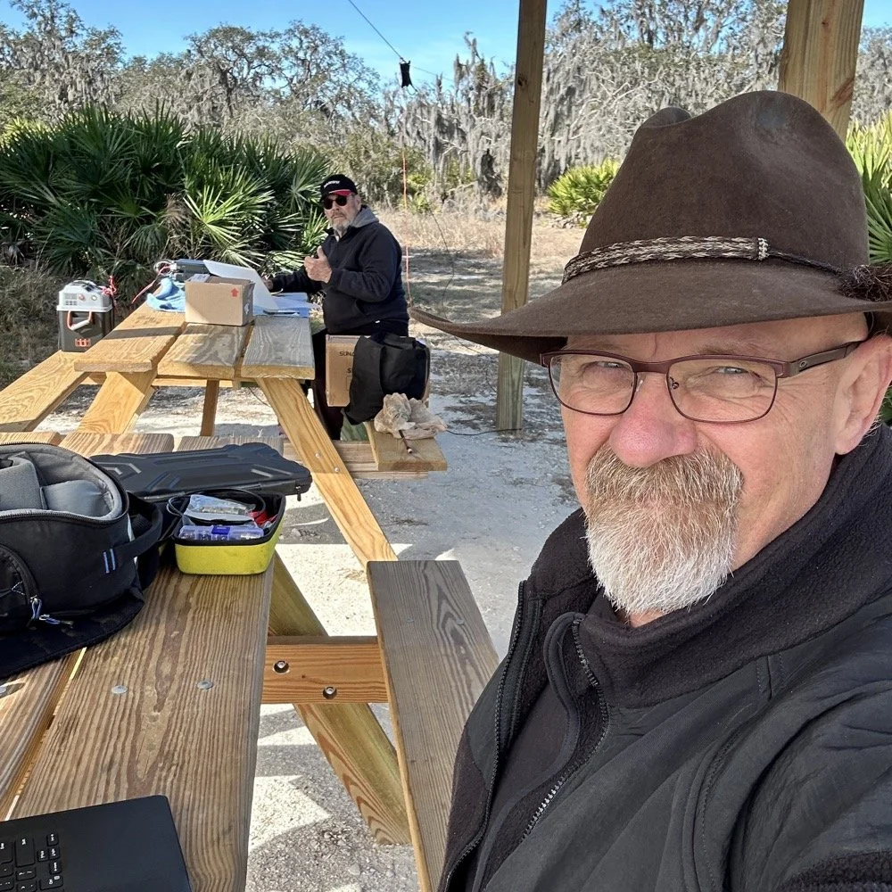
Today I had the pleasure of meeting Chas NA2B for our first joint POTA activation at Moody Branch Wildlife Management Area (US-6317) in Florida. What started as a chance encounter on the POTA spot page turned into a memorable 4-hour operating session that netted 104 total CW contacts between our two stations.
Today I went to a POTA park to meet up with Chas NA2B, another amateur radio operator that lives just down the road from Chito Branch nature Reserve where I have been spending a lot of time here lately. He saw I was at the park on the spot page and simply hopped in the car and drove over for an eyeball QSO and to see if I wanted to meet up with him at some point and setup for an activation.
This blog post will be an amalgamation of both discussing the activation as well as my new friend.
Planning the Activation
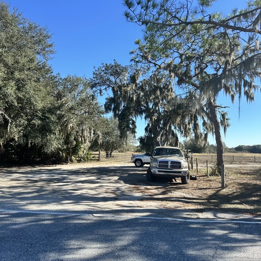
We communicated a good bit over the past week via text to line up a good day, (turns out every day is a good day for Chas…haha) and chose Tuesday as I had some business to attend to on Wednesday and the weather was way warmer than the previous day. The weather actually turned out to be about perfect to be honest about it. We agreed on Moody Branch US-6317 and 9:30 as the start time. We had planned to operate till about 2 if things were going good so on the day of, I load up the truck and head out. It takes about an hour to get there from where i was staying so I stopped and grabbed coffee and snacks along the way. Who doesn’t want a caffeinated CW op on the other end of their QSO???
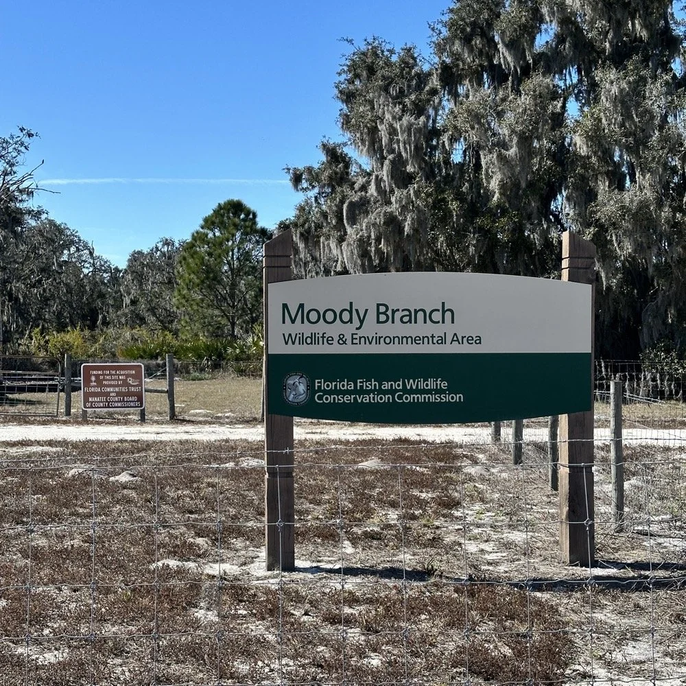
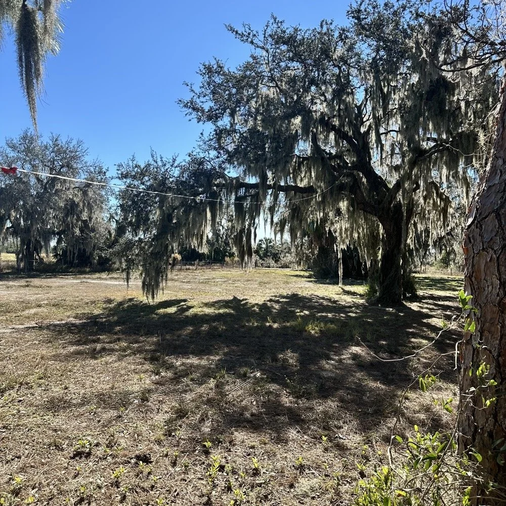
When I get there I am greeted with the standard issue Florida DNR signage and to my amazement there is a pavilion for us to operate from! Now to be fair, Chas had told me about it and the proximity to the parking lot. You see it was literally 15 feet from my truck to the table. Having the table this close allowed for an incredible amount of gear to be brought out. HaHa
Chas had already arrived and was setting up in the back of the pavilion so that I could have the closer spot and access to some really good trees to hang my antenna in. I decided to setup the antenna “properly” by putting the antenna tuner at the antenna instead of at the radio. This should provide better radiation than using the tuner to match the feedline as part of the antenna system. I simply set the case on the ground and set the tuner on top of it and tied the antenna wire to the case itself. The distance was about 50 feet from the table so I had to couple both of my longest coax cables together just to reach the tuner out by the tree.
The Setup: Remote Antenna Tuner Configuration
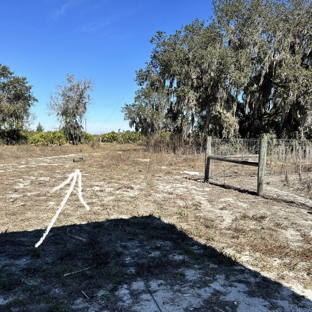
I put the antenna tuner way out here on purpose. The remote tuner setup keeps the feedline from becoming part of the radiator. This is important at it creates a more efficient antenna overall.
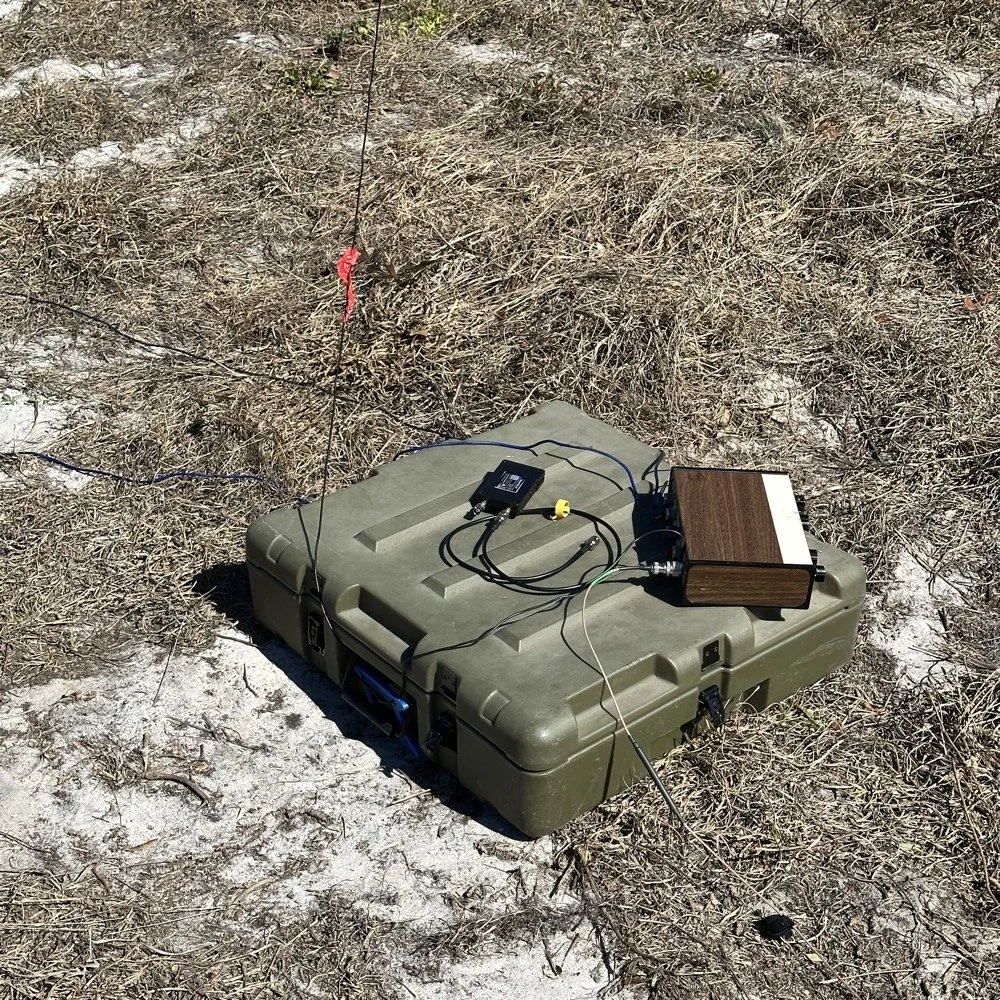
Since it was so far from the table, I just left the nanoVNA with the tuner so it would be nearby when I wanted to make band changes, of which there was many!
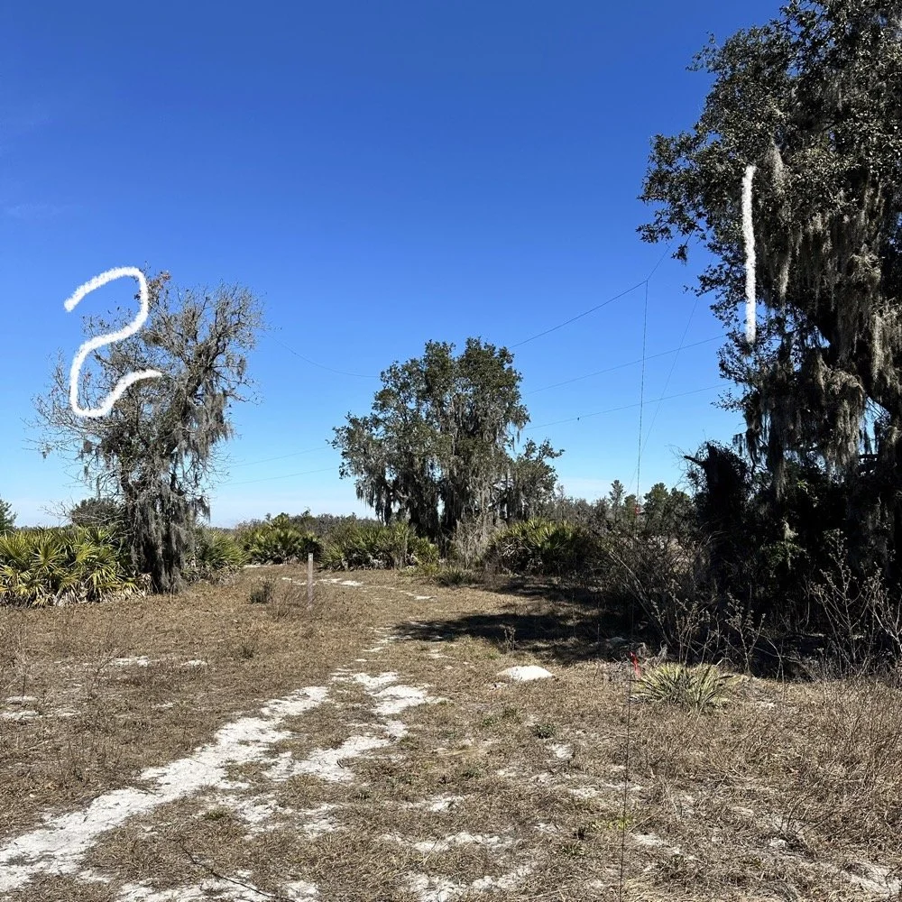
I strung the wire up like an inverted L type from tree 1 to tree 2 and tuned it for 40 meters to start with. Today I chose to start there as I was wanting to make contacts on all the bands I could with the Penntek TR-35 QRP radio. I also decided at the outset that I would work bands other than 20 meters today to see what I could come up with. I usually seem to have great luck with all the bands…other than 60 meters so far… haha. I also chose to run 10 watts or less all day too…well except for 40 meters, I ran 40 watts on 40 meters and still only made one FT8 contact there… lol. The band was just too noisy for me to hear anyone.
Equipment: QRP vs. Comfort
I only ran 10 watts or less the rest of the day because I didn’t have my large battery with me that I bring to power the sBitx at full power. I only had my 8 Ah battery and I didn’t want to deplete it early. I also had the 3Ah battery for the TR-35 and used it with that radio, but those were the power sources I was constrained to. This made me have to work a little harder for contacts, but it also made it a lot more fun to get DX stations in the log! I got at least 2 European stations in the log so I know it doesn’t take a ton of power to do it.
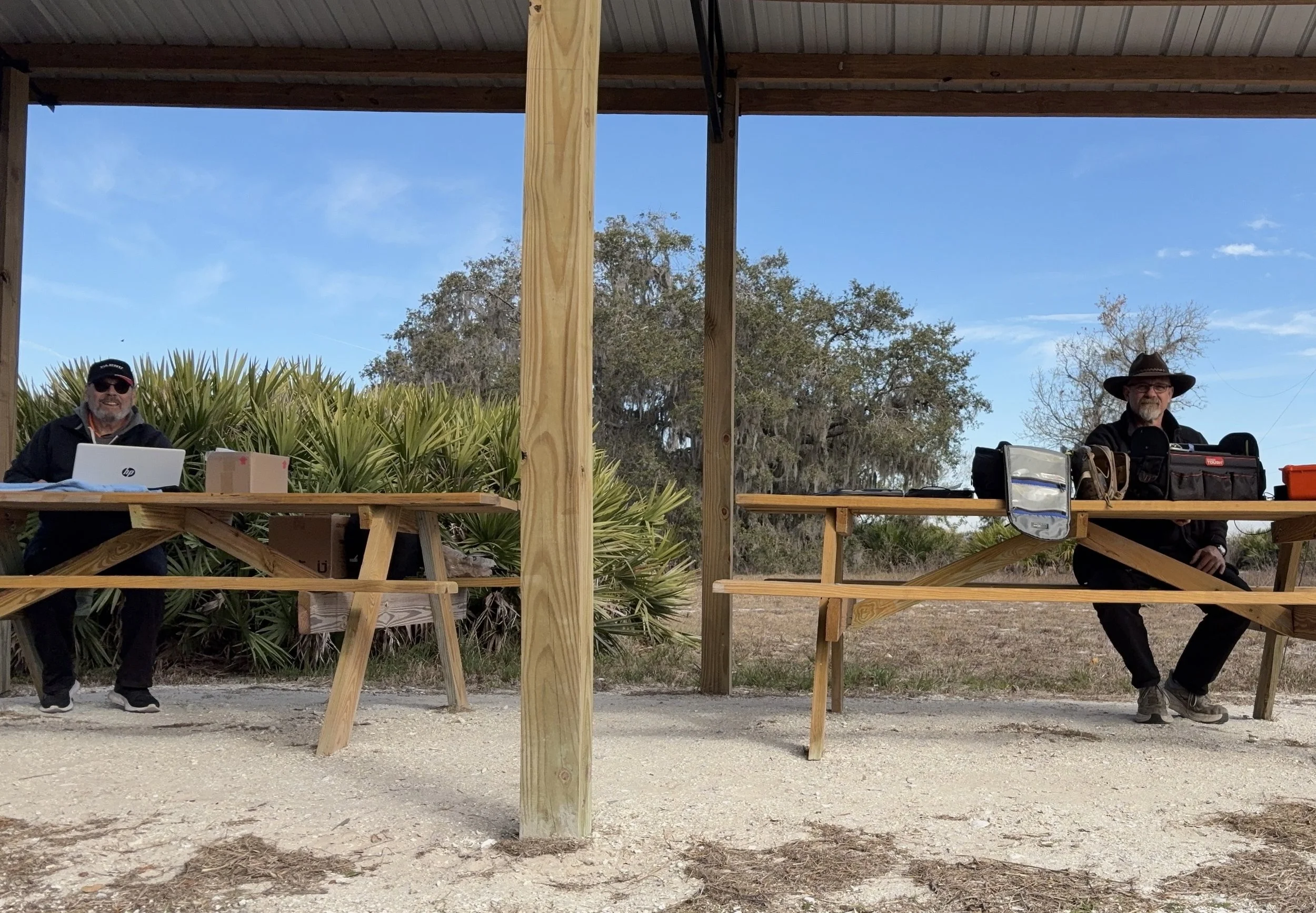
WK4DS (left) and NA2B (right) running simultaneous CW pileups on different bands at Moody Branch
Once setup I used two radios, the Penntek TR-35 QRP rig and the HF Signals sBitx V3. Both of these radios are cool in their own respect. I like the sBitx because I can run FT8 without needing to also connect a computer to the radio. The sBitx will internally log the contacts too so I could theoretically do an activation then when I get back home, down load the contact list and reformat it in ADIF and send it to the POTA site. That is kinda cool. The Penntek TR-35 is small, light weight and has a great receiver in it as well as awesome filtering. This little radio has everything you need and nothing you dont.
Above is me and Chas running pile ups on two different bands at once! We were both running CW today and at times I struggled to hear as my side tone and his were the same. I solved this by adjusting the side tone up a little so then mine and his were different ever so slightly and I could hear mine easily again. I think Chas stayed on 20 meters the whole time today. He racked up 61 contacts with the simple wire antenna. What a day in the field!
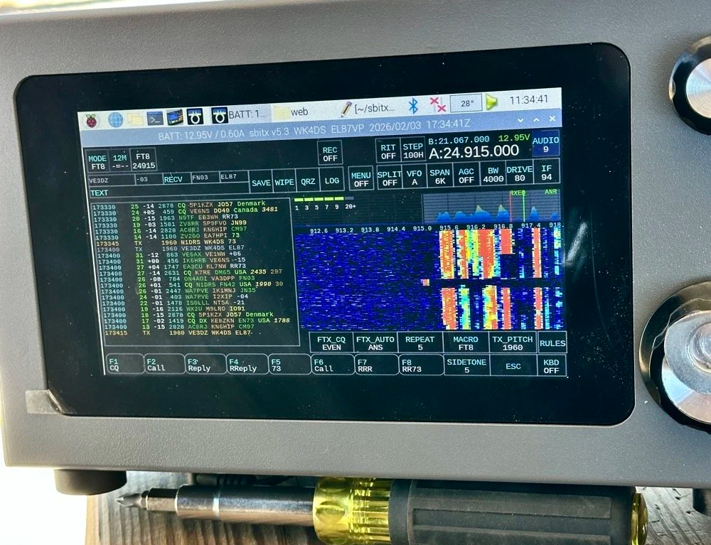
sBitx V3 running FT8 with new color-coded software from the open-source development team
This is what you see with the latest software release from the open source team on Github. This software has been made VERY good by this team of dedicated people and if you want to use this software yourself, just follow this link to JJ’s github page to learn more.
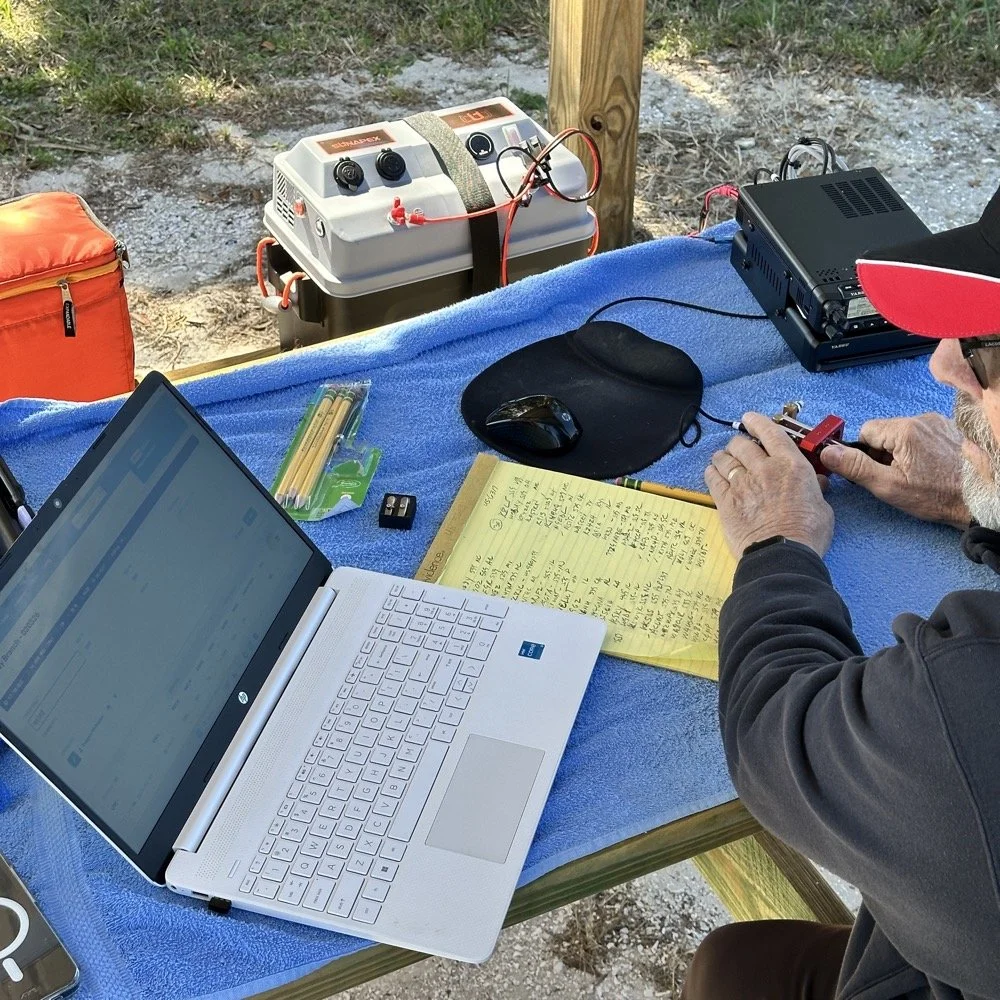
NA2B's minimalist CW station: paper logging, pencils, and a clean operating position
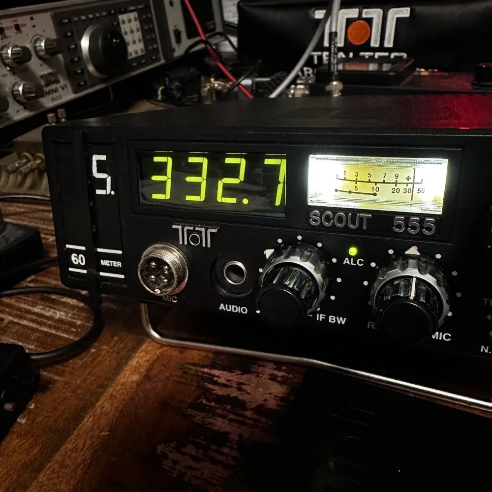
Chas had a really clean operating position today. He had plain pencils, which will ALWAYS work, a pencil sharpener and notebook for log data. He was in a blissful state. I also like the battery pack he has too. If I had brought my 36 Ah battery, I would have brought the Scout 555 out and ran it as well. Maybe forgetting it was a sign that I needed to let that radio rest a little…haha. His station looks so clean though, I was impressed.
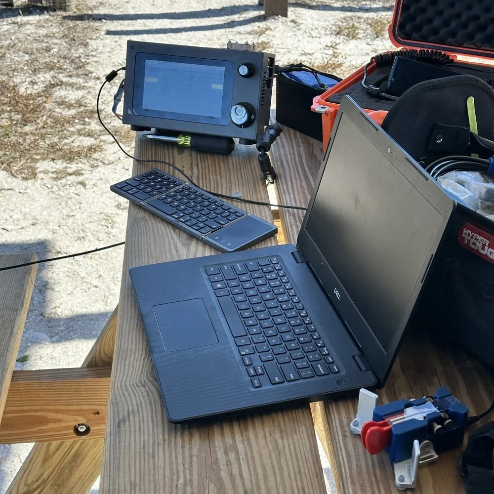
My station on the other hand looked like I set off a “ham-grenade” lol… I had the logging computer, the foldable keyboard for the sBitx and the whole Penntek station was just piled in the orange storage case. Along with all that, I also had all sorts of other stuff that isn’t in this photo scattered around the table… It was kinda crazy how much crap I brought out.
Operating Highlights
Chas setup his camera and grabbed this photo of us below for the blog. I like how his station has one box on the table and mine is covered in stuff! HAHA!
I will be honest, it was a lot of fun just hanging out while doing the activation. I do so many of these by myself that I forget that I can have someone with me while I do this.
We didn’t get in a hurry, we just took our time and whatever calls got in the log is what we got. There were a couple of time we both had decent pileups to work through, him more so than me as he had more power and 20 meters typically has more operators on the band. It wasn’t about QSO count…till it was… but all day we just made contacts and played radio.
Right before we finished for the day, I asked Chas how many contacts he had. Chas had 60 calls in the log and I had 38. I told him that we needed to have an even 100 calls between us before we stopped for the day. This total number of QSOs was completely arbitrary, but a cool little milestone none the less so we pushed on for a little longer. We finished the day with 104 total calls in the logs. Win! Chas had 61 as a final count and I ended up with 43! What a day!
Multi-operator POTA setup at the pavilion - note the contrast in station complexity!
After about 4 or 5 hours of fun and games, we decided to break down and head back to our wives to get some lunch. It was a great day and I am glad I made a new friend as well.
Activation Summary:
- Park: Moody Branch WMA (US-6317)
- Operators: WK4DS & NA2B
- Total Contacts: 104 (43 WK4DS + 61 NA2B)
- Mode: Primarily CW, some FT8
- Bands: 40m, 30m, 20m, 17m, 15m
- Radios: Penntek TR-35 (QRP), HF Signals sBitx V3, Yeasu FT-891
- Power: 10 watts or less (QRP), 40w on 40m, 50 watts on 20m
- Antenna: Inverted L wire antenna with remote tuner, (Chas ran a random wire)
- Duration: 4-5 hours
You can help support this website by using these Amazon Affiliate Links:
QRP/Portable Radios:
Antennas & Tuning:
CW Equipment:
Power & Accessories:
Organization & Transport:
BONUS ITEMS
73
WK4DS - David
![Ten-Tec Scout 555 60m Band Module: IF Filter Redesign & Final Testing [Part 4]](https://images.squarespace-cdn.com/content/v1/5d17806ce65eba00011667cb/083bf6b4-e926-4837-8a07-9c333538b44c/IMG_1543.png)
Ten-Tec Scout 555 60m Band Module: IF Filter Redesign & Final Testing [Part 4]
Today saw me finish the TenTec Scout 555 60 meter Band Module Project in the workshop, now it is on to phase 2, testing in the field… I had wanted to rework the filter in the IF stage as it was not great from before. I was able to get a signal out of the radio, but the filter shape left something to be desired…
This is the final episode in my Ten-Tec Scout 555 60-meter band module series:
- Part 1: Initial Conversion and Filter Design
- Part 2: Crystal Selection and Mixer Circuits
Today saw me finish the TenTec Scout 555 60 meter Band Module Project in the workshop, now it is on to phase 2, testing in the field… I had wanted to rework the filter in the IF stage as it was not great from before. I was able to get a signal out of the radio, but the filter shape left something to be desired…
The first chart image is of my filter after I got the radio to work. This is not what a bandpass filter should look like. The lower photo is of a factory TenTec VERY narrow bandwidth 40 meter bandpass filter. Turns out, this is almost impossible to replicate with discrete components that are not adjustable…as you will see. They used two tunable inductors to achieve this filter shape. I almost went to the trouble of adding some trimmer capacitors to mine, but as you will soon see, I felt it wasn’t needed. I soon learned what a filter Q is and why it matters when your trying to build a filter. I used some online calculators to get the component sizes for the filters and after messing around with a couple, I found one of the calculators had came up with numbers that were actually able to be made in my shop.
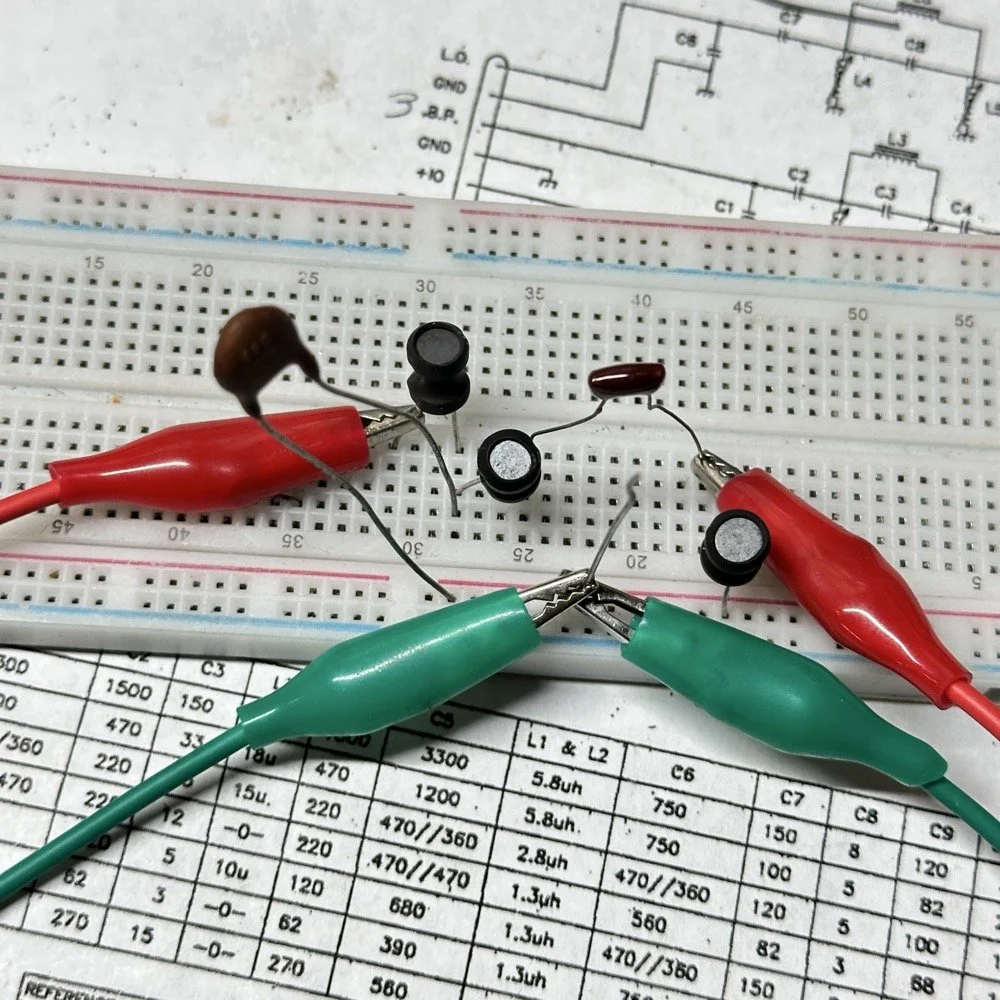
Armed with this information I decide to breadboard this filter first so I could tinker with it before soldering it to the band module circuit board. This, as it turns out, is a terrible idea if you plan to simply transfer the parts to the board and solder it all together. There is SO much stray capacitance and inductance at RF frequencies with a breadboard that you can build up a circuit, but when it comes to making the final item on perf board or Manhattan style, that you WILL use different values.
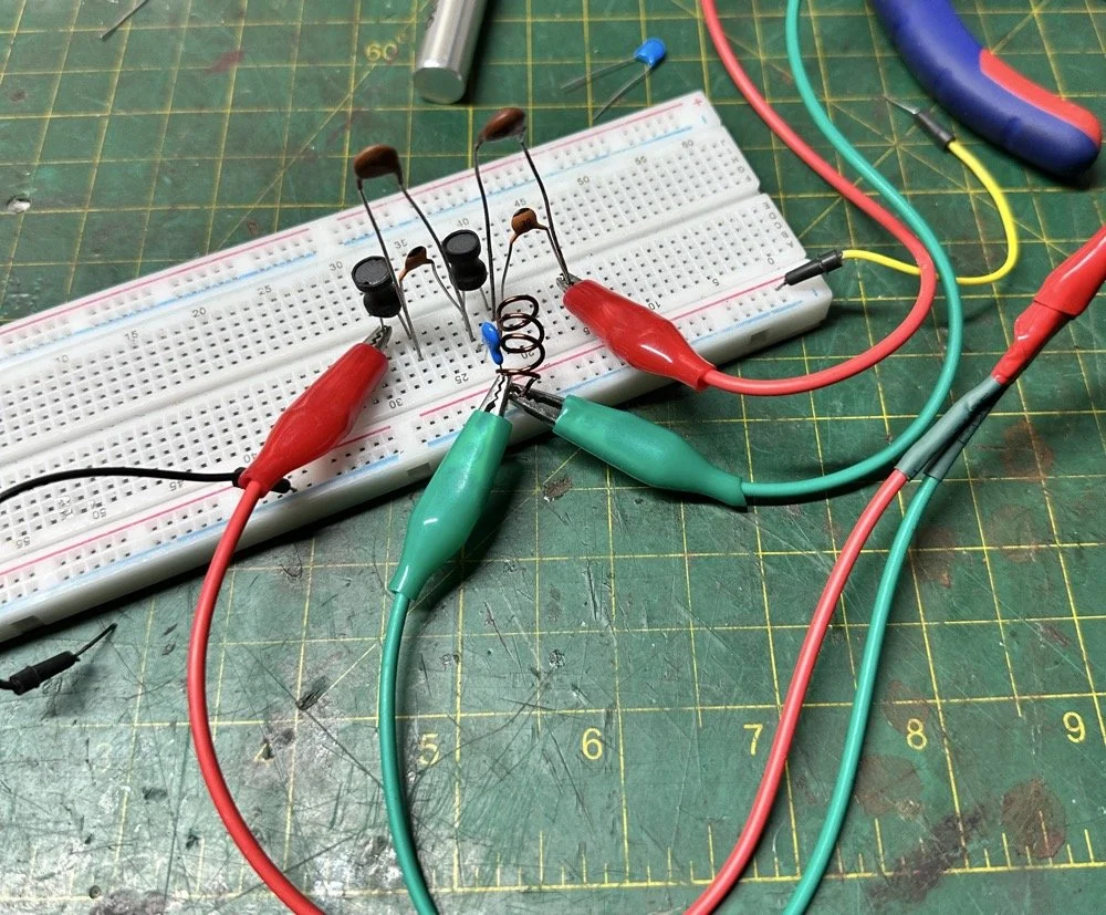
Looks good doesn’t it? Well look at the plot below! It actually looked great! It did have some insertion loss that I was not super happy about, but that plot looks great! Yes, the one inductor is hand made, I didn’t have one small enough in my little kits to work here I so wound one for the job. Notice how long the leads are on those components, that will come into play very soon…
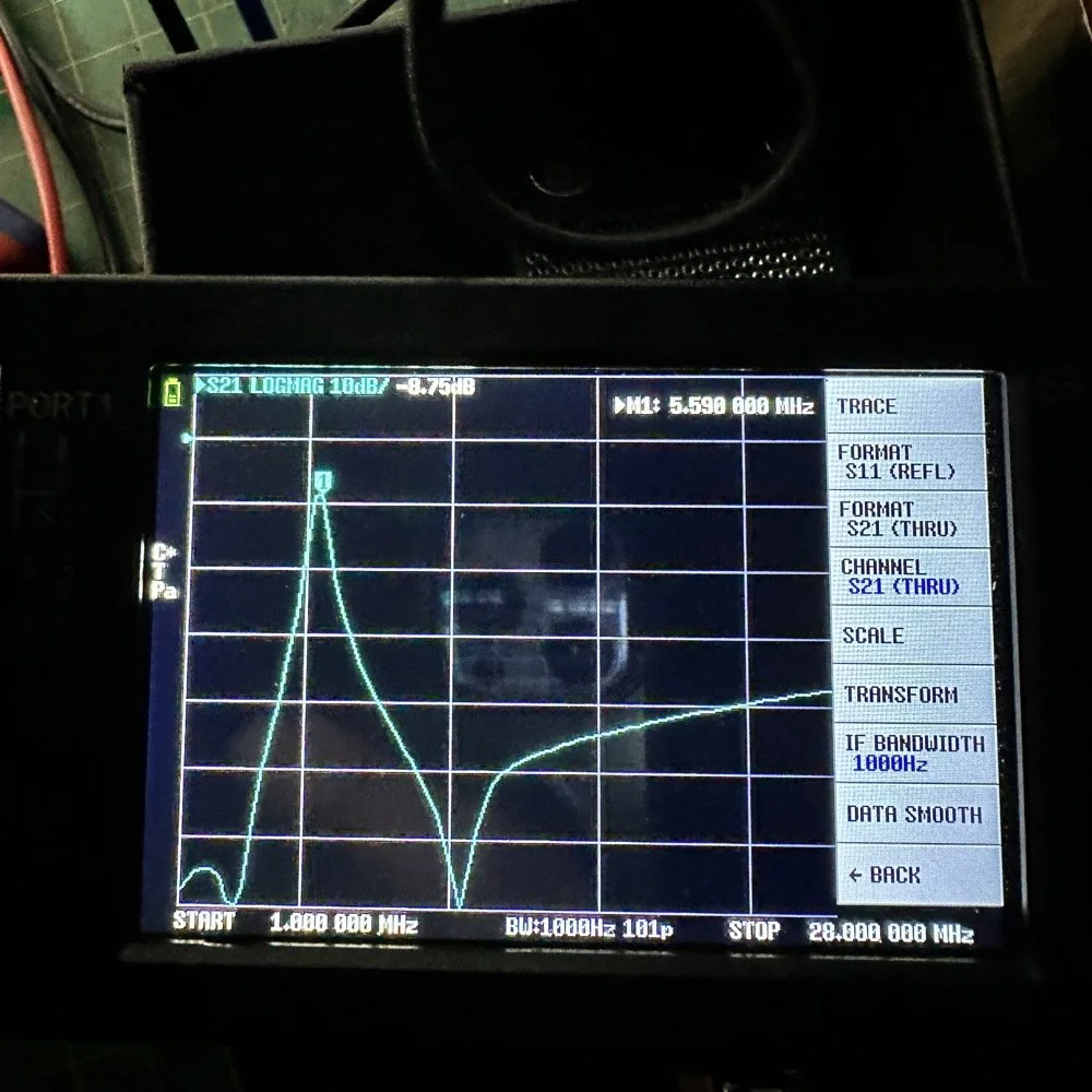
I may have gotten a little aggressive with the passband width… I think it was set to 200khz or maybe 500khz, but it was not much. I think the values I put into the online calculator were 5.4mhz center frequency, 500khz bandwidth and 3 LC stages in a “T” configuration. The bottom line on the chart is -70dB which is unbelievable! This thing was incredible! So I get the 60 meter module out and take it apart and strip out the old filter I had previously built wholesale leaving a clean slate for the new filter…
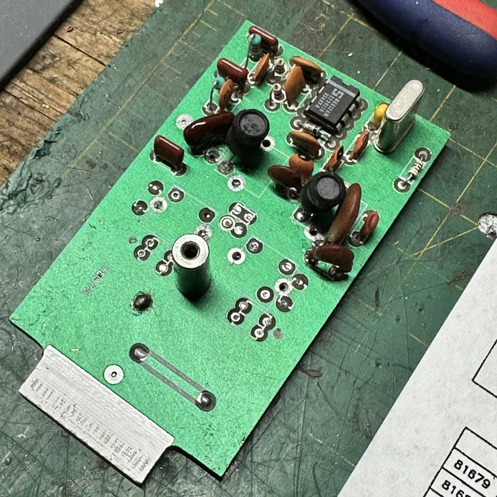
After I had the old filter gone and cleaned up a little, I cut me a pad as the new filter layout and the TenTec layout are different so I wanted to not have to permanently alter the circuit board other then removing the old components. This pad became the central connection point for the three stages. A little hot glue and I was in business! I simply tinned the whole top of the pad so I could land part leads where ever I wanted on it. This worked really well…much better than the filter I am about to build as it would turn out.
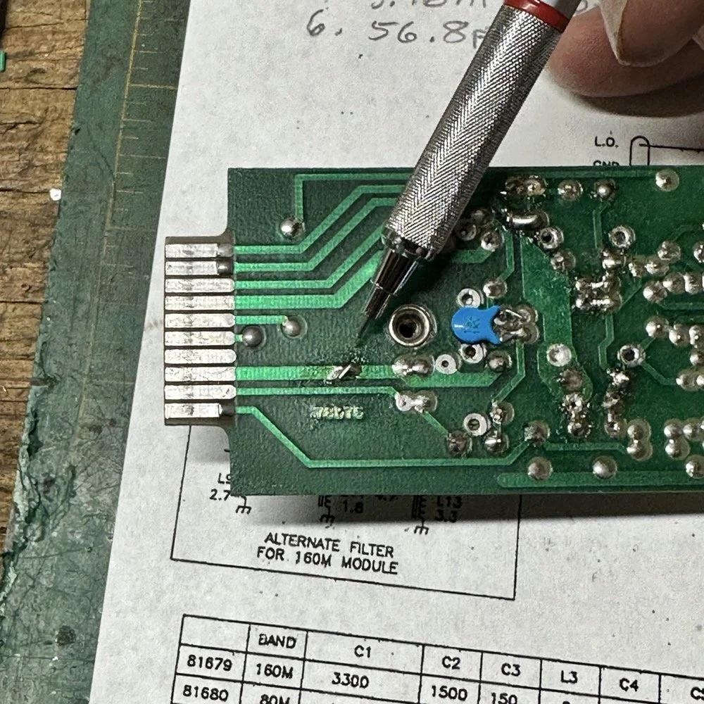
SIDE NOTE ABOUT MODIFYING SCOUT BAND MODULES:
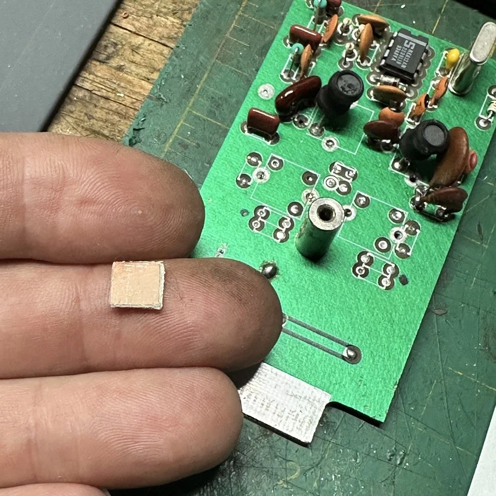
What I am pointing out in these two photos is a home made Via that I added. You see, when you remove the canned tunable inductors from the board, turns out you break the grounds. TenTec decided that since these things were going to be here anyway, might as well use them for something. So they apparently decided to make them connect one ground plane to another in a couple of places on the board. Once you remove the cans, you lose a critical ground path…or two. I took a finger drill and a very small drill bit and drilled a hole from one trace to the ground plane on the opposite side(I am confident these are only two layer boards), then I soldered a bonding jumper wire in the hole so both planes would once again be connected again and all the stuff would continue to work properly. You also get to see the old homebrew filter in the below photo as a bonus.
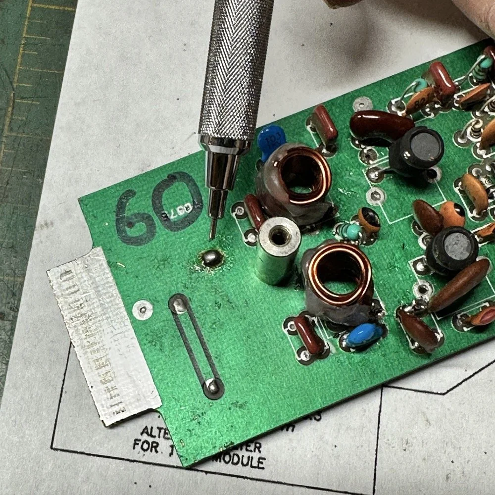
Below is the result of me simply attempting to move the parts over to the circuit board and soldering them in place… What a mess. I started with the exact parts you saw on the breadboard, but when I connected the nanoVNA to the filter I found the center frequency had moved up 500khz! It was now pushing my desired frequency out of the passband!!! I was seeing something like 16dB of loss at the desired frequency.
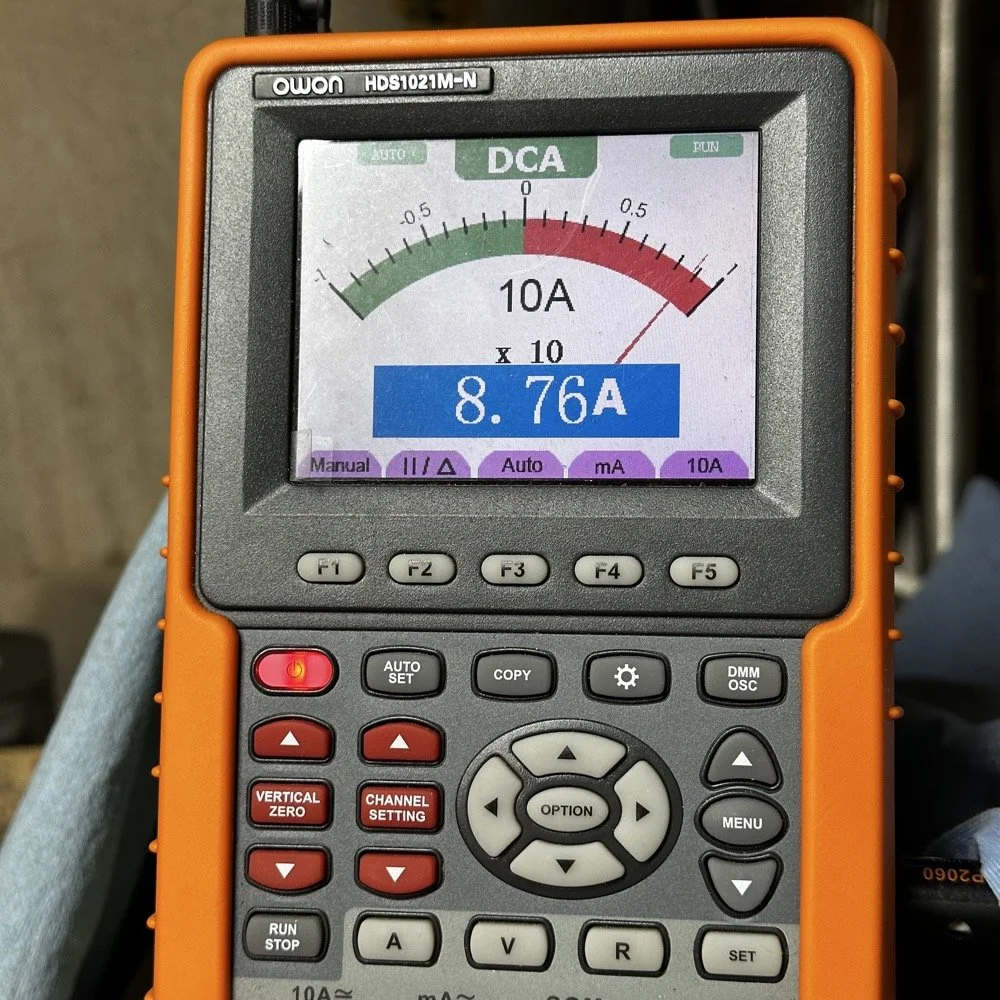
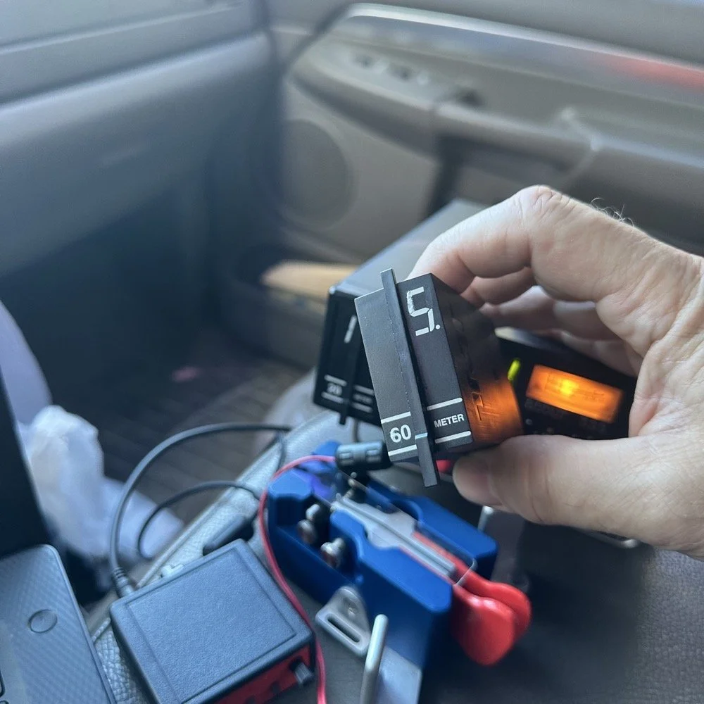
This is the world of ultra high Q passband filters made with inductors and capacitors I guess. Once I removed all the stray capacitance from the breadboarded system, all the capacitor values went down enough to make the filter not usable. That is why you see the mess below, I didn’t have room for the trimmer caps I have on hand so it was good ole trial and error method instead to get the passband in the right spot. To be fair, this mess actually worked, it just had something like 12 or 13dB of insertion loss in the filter which made the output power go way down. I used the amp meter to check it and the current draw on transmit with this filter was 1.8 amps and the current draw with the factory 40 meter band module was 9.3 amps. So I took a break and grabbed some food and went back to the drawing board…
I am going to admit something here that might make some people unhappy with me…I decided to use Claude AI to see what it would come up with for a filter design. I gave it all the parameters I had used earlier and (since it is a chatbot after all) had a conversation about what my goal was. I decided to move the bandwidth out to 1mhz giving me a decent shot at making a working filter without adjustable parts and using only what I had available on site.
This AI model came up with a “T” filter but instead of the center 2 LC components being in parallel, they were in series and so I built it. It tested really bad as far as rejection goes as it only attenuated about 8 or 10dB across the whole band and looked more like a poorly designed high pass filter instead. This did give me some inspiration though. So I went back to the online calculators that are there to figure part values for you and changed my approach. I went to this website and just made a low pass filter and then a high pass filter and coupled them together with an inductor. Why did I choose an inductor? Because all the capacitors I tried kept increasing the losses in the filter output is why. As it turns out, if you attenuate the IF signal in the radio the output power get lowered and the radio goes “deaf”…
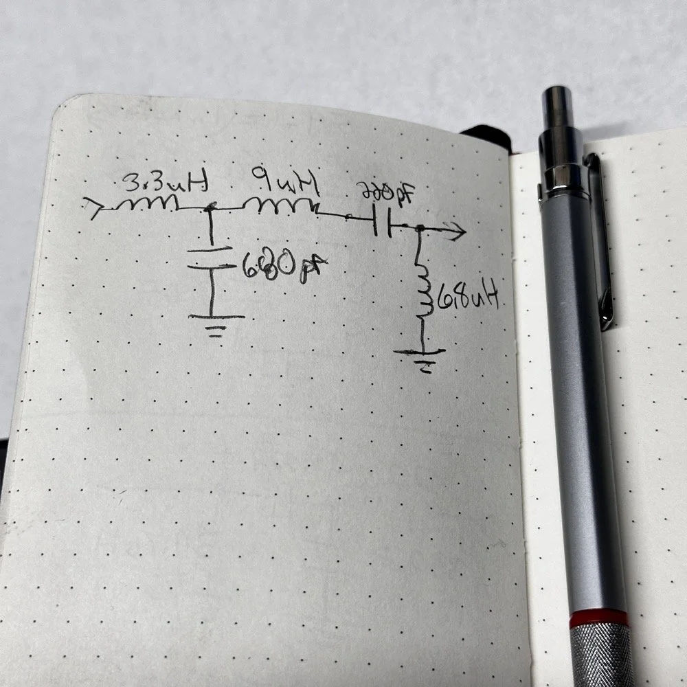
Below is what I came away with finally. Yes, only 3 inductors and two capacitors.
Below is the filter shape for this simple filter design too. It is a lot better than what I started with and I was able to build it with parts that I had available to me at the time. Could the passband be narrower? Yeah, it could, but I am not going to throw too much shade at this filter. This is what ham radio is all about in my book, experimentation. The marker is at 5.64mhz which is 250khz above the highest place I can transmit so I know this filter wont attenuate my signal and the radio will work as it should.
The original values for the filter ended up being wrong, but I simply did what I did in the previous filter build and just used it as a jumping off point and started switching out parts one at a time with different values. This tactic coupled with looking at the nanoVNA to see what the new part did to the filter shape gave me the results you see. At first I didn’t write down what I had done, but it quickly became apparent I needed to note what I had done and so things progressed much more quickly once I did.
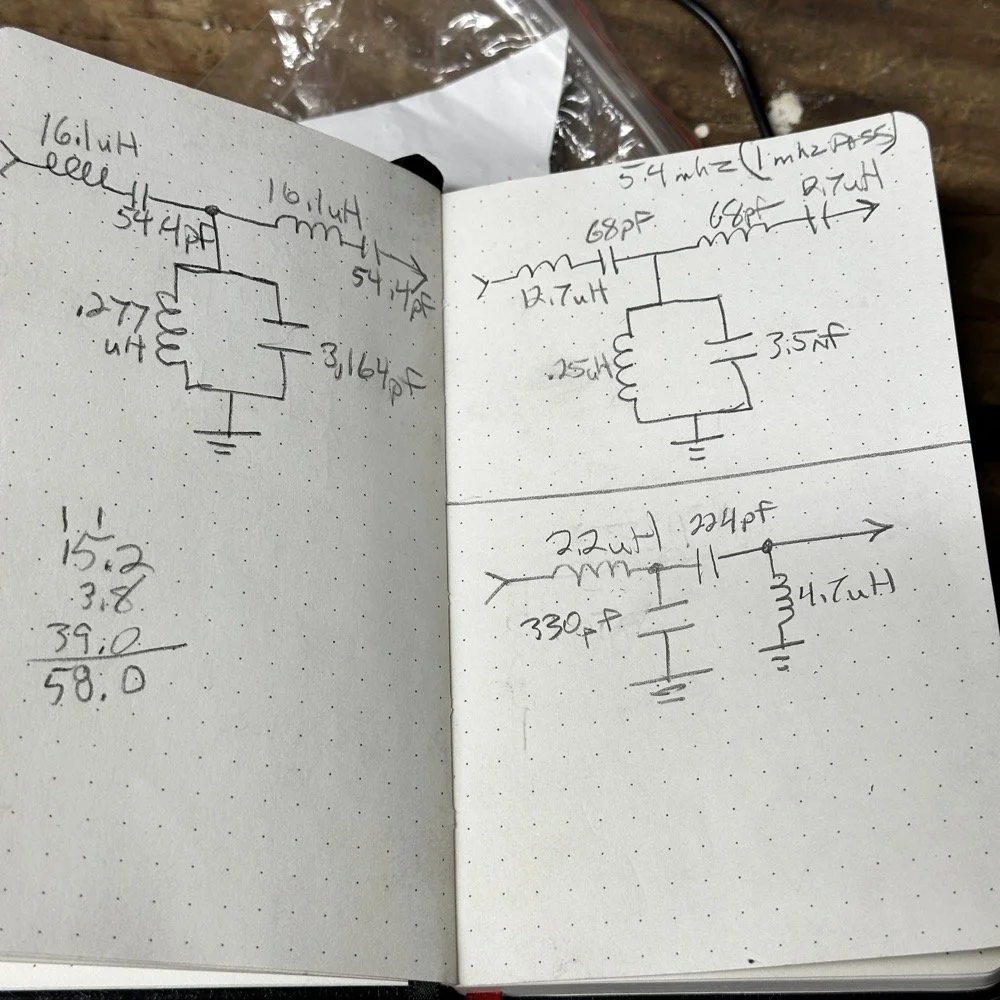
The above photo ( bottom of the second page ) is what I started with on this part and the lower photo is what I ultimately ended up with for the actual parts I used to build the filter. You can see where I was trying all sorts of stuff to get a working filter, these are not the only sketches either…
This is what I ended up with ultimately to get the filter shape above. The impedances are wrong, I am sure as I didn’t take them into consideration at all, but the radio is working correctly now (from what I can tell) and transmits almost at full power. Shoot, they could be right and I just got them right by accident, I really don’t know to be honest.
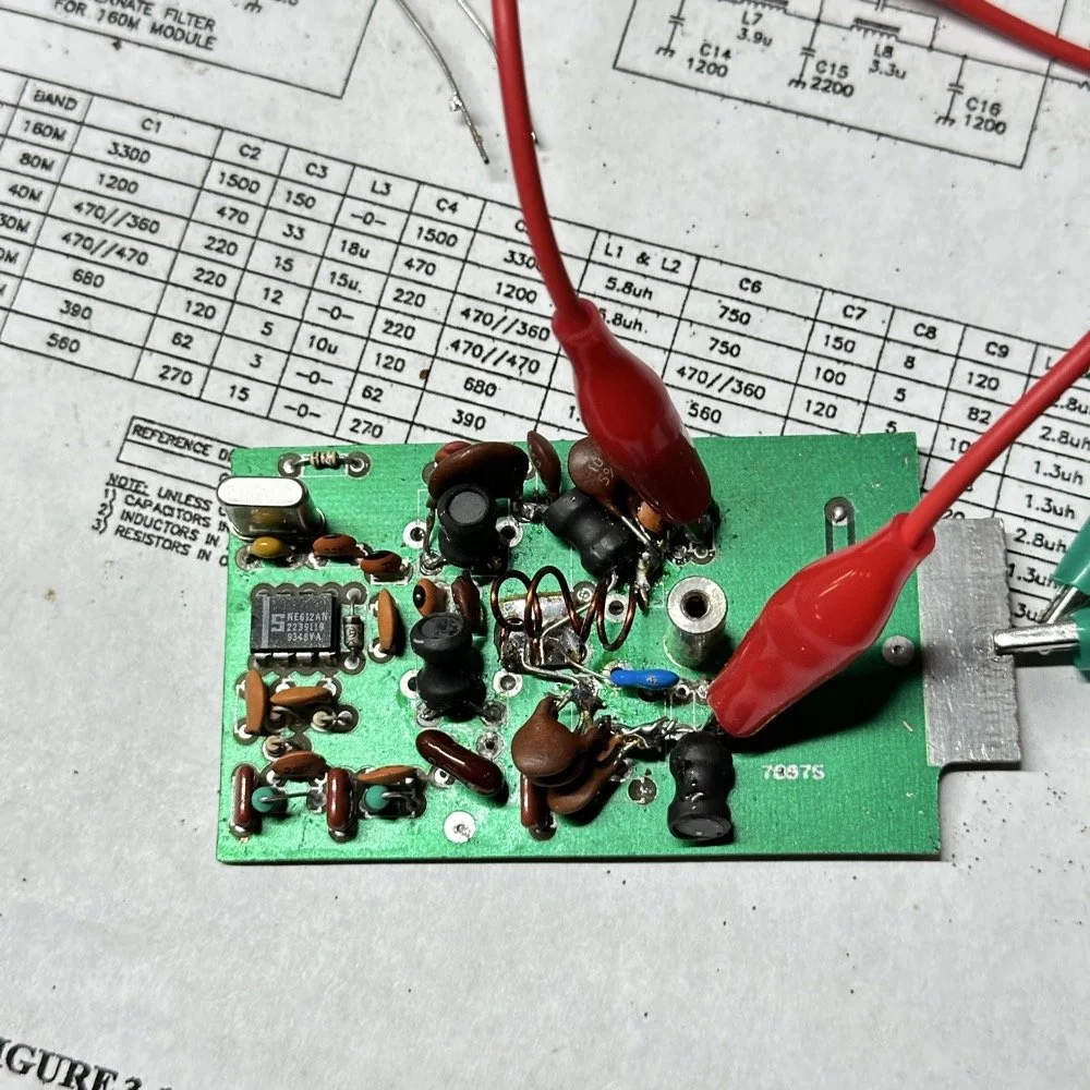
This is the output power draw now for the 60 meter module on the same radio as the 40 meter module previously compared. I can live with that! I checked it when I got into the shack at the house and it is a little over 35 watts into a 1.3:1 SWR load. That will work just fine for me. (Note: The current reading was into a 50 ohm dummy load at the workbench so I don’t know the exact current draw in the shack.) This radio will produce more output power too, I have it dialed back on purpose to about 40 watts for the 20 meter band module that I use with this radio.
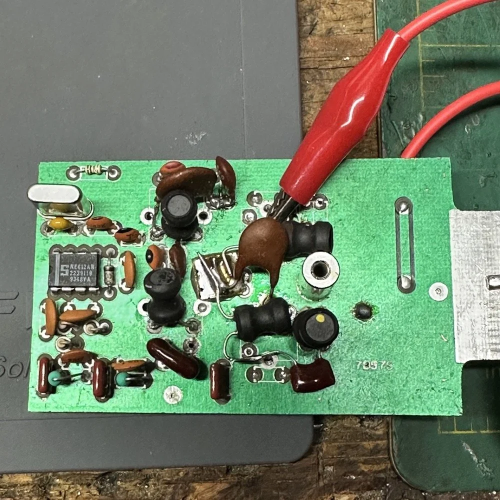
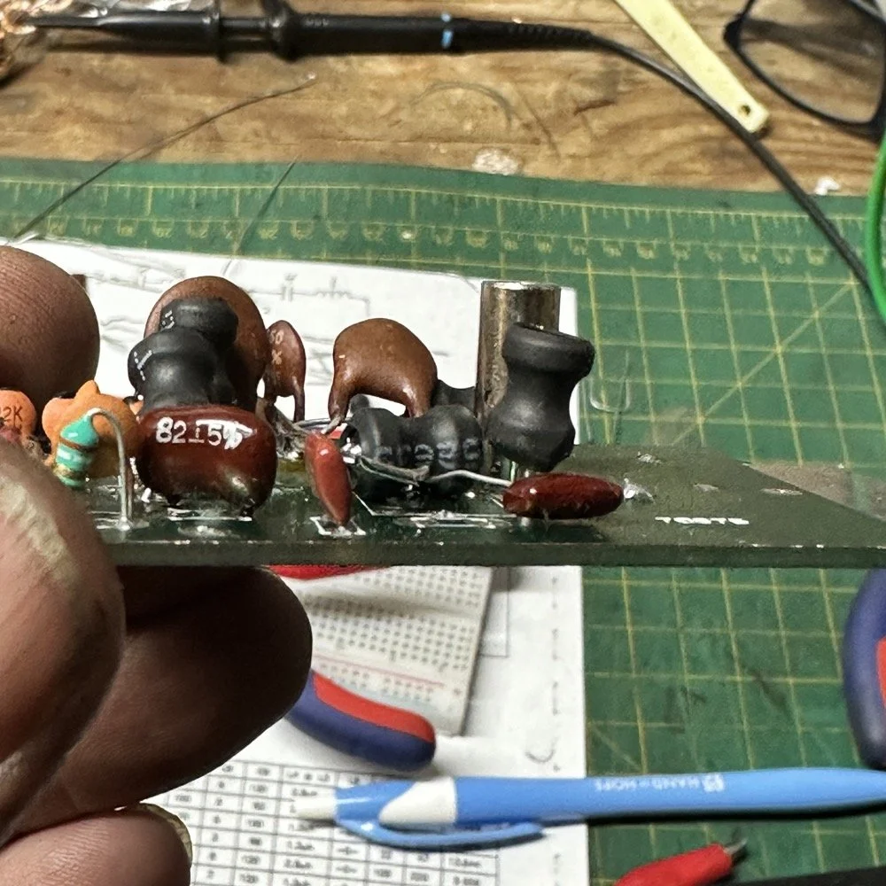
This is what the final filter looked like when I was finished building it. This looks a lot better than that mess I started out with above. Not overly complicated and generates a respectable filter shape. The radio sounds good too. So I am happy with this.
Side note about the above photo, I had noticed in my original filter design that the orientation of the inductors made a difference in the filter profile on the nanoVNA so I started marking them with a paint pen to remember the orientation. This filter didn’t seem to care too much about that for some reason but the original cared ALOT.
The side view photo shows something else the I have not mentioned in these write-ups. The filter has space constraints. The filter can not be taller than that metal post or the other circuit board with hit the parts and the parts can not go past the post either as that is the space for the output low pass filter from the other board. So parts count matters…
It feels oddly satisfying to see the finished module and to use it in the shack. All I did last night was listen to some stations having a QSO and how well it could hear them. I also dialed up the webSDR again and listened to myself calling CQ for a bit with no takers on a different channel. I know the radio is working as the listening station in Utah could hear me…
Tonight I hope to find a chance to jump into a QSO with someone and see how it sounds to them.
I hope this has inspired you to do something with your gear whether it be build a kit or modify a device to do something new or different or even to repair something you have that is not working now…shoot maybe you will learn something you didn’t know before! That is what has happened to me on this journey, I have learned a lot about how filters work and what affects them in use. I am starting to understand impedance matching the stages as well as insertion loss. A lot of things I never understood before are now becoming more clear. I also have a much clearer understanding about how the TenTec Scout 555 radio works as well…
Thanks for following along on this 4-part journey! If you build your own 60-meter module for the Scout 555, I'd love to hear about it. 73!
You can help support this website by using these Amazon Affiliate Links:
QRP/Portable Radios:
Antennas & Tuning:
CW Equipment:
Power & Accessories:
Organization & Transport:
BONUS ITEMS
WK4DS - David
![Ten-Tec Scout 555 60m Band Module Build: Final Filter Tuning & Field Testing [Part 3]](https://images.squarespace-cdn.com/content/v1/5d17806ce65eba00011667cb/c2e621e7-9bb7-4b40-b20f-7c5c2dc8be7d/IMG_1257.JPEG)
Ten-Tec Scout 555 60m Band Module Build: Final Filter Tuning & Field Testing [Part 3]
Today I took the newly minted 60 meter band module for the Ten Tec Scout 555 out on it’s maiden voyage to a POTA activation. I made a contact in the shack with it before leaving on my short trip to Florida so I felt confident it was ready to use. Today we are discussing what happened and what is going on from there with the 60 meter band module project. (Spoiler Alert: It kinda wasn’t really ready yet…)
Today I took the newly minted 60 meter band module for the Ten Tec Scout 555 out on it’s maiden voyage to a POTA activation. I made a contact in the shack with it before leaving on my short trip to Florida so I felt confident it was ready to use. Today we are discussing what happened and what is going on from there with the 60 meter band module project. (Spoiler Alert: It kinda wasn’t really ready yet…)
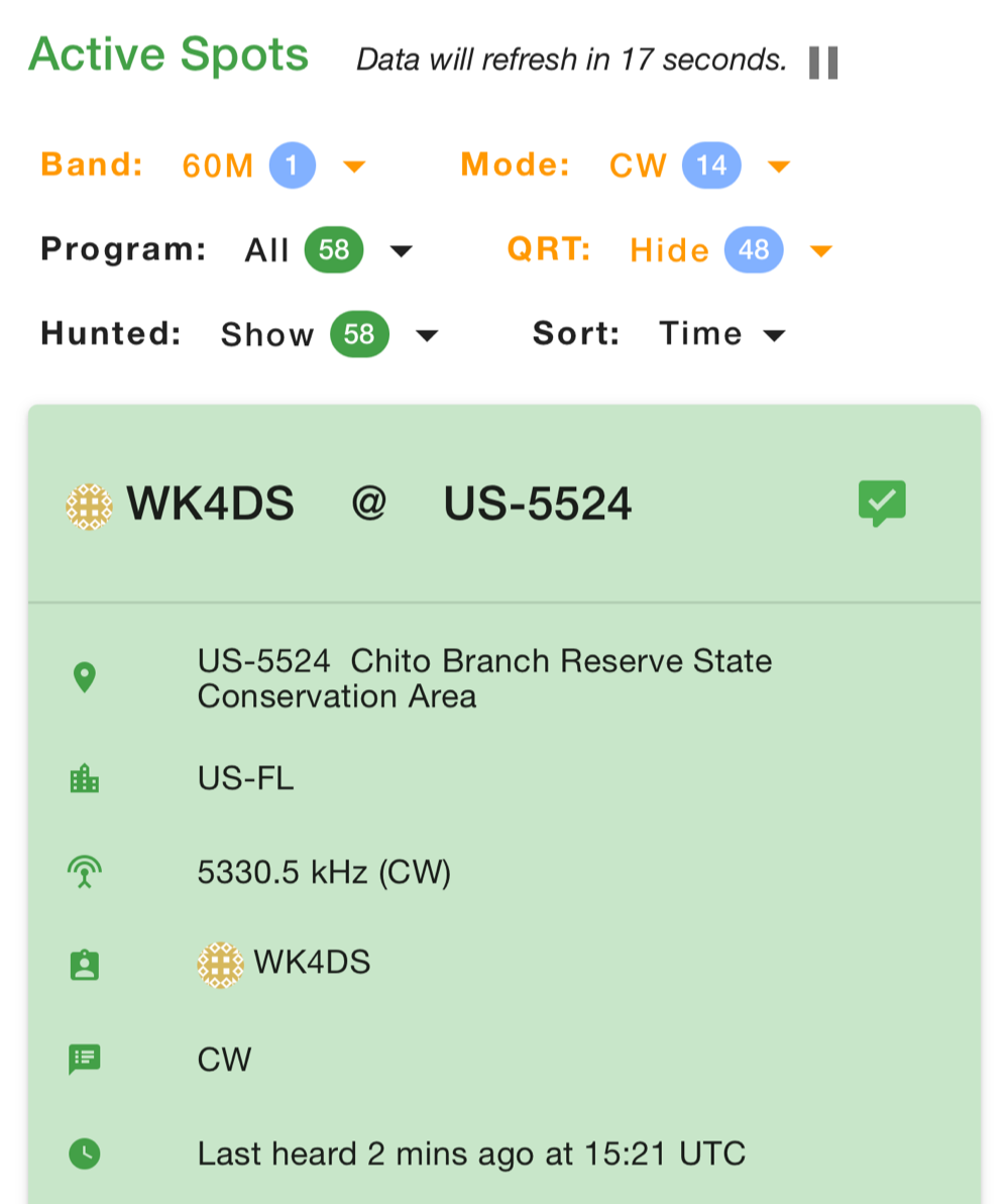
As you can see from the spot page report below, I was the only one on 60 meters this morning and it was roughly 9:45 (might have been 10 to be honest, I cant remember) local time before I got everything setup and running. This made 60 meters not a great choice to be honest for a daytime band. The 60 meter band is a great evening and really early morning band, but once the sun comes up these low bands tend to get really noisy. The band noise was quite low to my surprise today. I usually get a good bit of man made noise in this spot so I was pleasantly surprised when the noise floor was really low…or the band was closed. Who knows at this point?… I am starting to lean towards the band being closed as I couldn’t hear the FT8 crowd either, and those guys are ALWAYS on the band if it is open at all.
Undaunted by this and the lack of any kind of signal on the band, I setup and started calling CQ…and called …and called… then I finally got a station in North Carolina ( WA4CHJ - thanks for answering me, I really appreciate it. ) and with that I had a call in the log on 60 meters with a Ten Tec Scout 555!!! I can’t be certain this has been done by someone else, but as far as I know, I am the first to make that happen! After calling CQ for about 7 more minutes with no answers, I noticed that the ALC light was not coming on when I would key the radio and it was showing about 20 watts forward power on the built in meter. I checked the SWR and it was fine so it had to be in the module. I tried calling for a little longer and started getting an odd kind of “hashy” crackle on the CW sidetone and when it would make this sound the power would go up to the normal level and the ALC would come on…Upon this realization, I decided it would be better to sideline the module till I got back to the work bench next week instead of risk damage to the module or the rest of the radio. It also occurred to me that the RBN never heard me, not one time, while calling on this day so the band must have been closed…
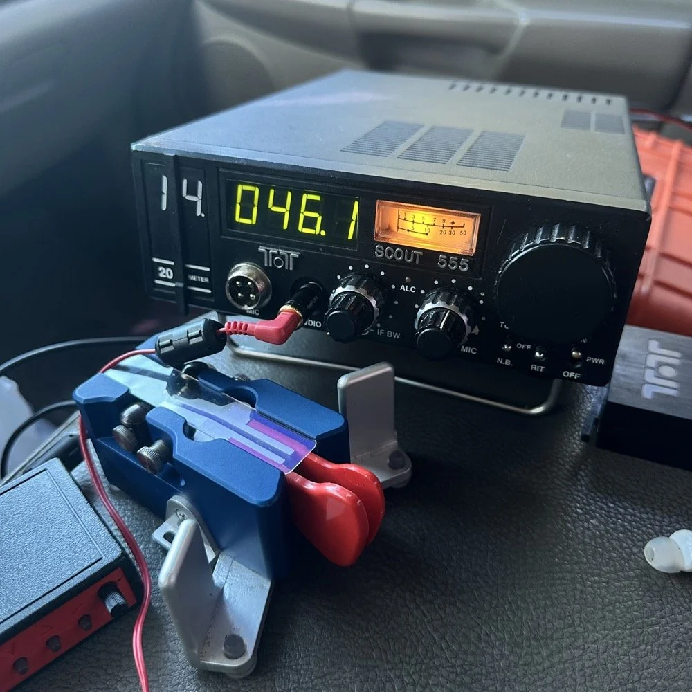
You gotta admit though, that setup below is kinda sweet… Also the frequency is tuned off by the side tone (this is normal for the Scout 555) so it is actually on 5.3305 mhz in this photo. (I checked it with my Omni-VII before leaving home so I knew it was on frequency)
I setup a long wire today since my vertical will only tune to 40 meters with the home-brew load coil and I was a little strapped for time and just used an MFJ manual tuner instead. This allowed me to get a 65’ wire up in the air and a couple of radials and run with it. I was able to tune it well into the 60 meter band with the null covering the entirety of the band space so no tuner changes were needed as I moved around in the band.
SIDE QUEST:
This little segment will be about the rest of the activation for my readers that follow those as well.
Today was a great day…once I moved to 20 meters! Turns out 20 meters was alive and well today with only about 6 CW activators on the band. This gave me plenty of room to find a nice quiet frequency as well as lots of hunters were out today as well. I tuned up on 14.047 mhz and started calling CQ, I think it took two calls max to call in a extraordinary pile up for me! The stations were deep and strong! I swept aside my normal pleasantries for the most part and compacted the closing to what I felt was a minimum and the calls just kept coming in! I worked 49 calls in 41 minutes! That is a record for me! At this point I literally called CQ one last time to make sure there was no one else waiting and got no replies so I immediately called QRT and shut down the radio. I was actually out of time and had to get the rig packed up since I needed to pick up the wife from class. This had to be the fastest 49 calls in the history of WK4DS amateur radio in my totality of radio… haha.
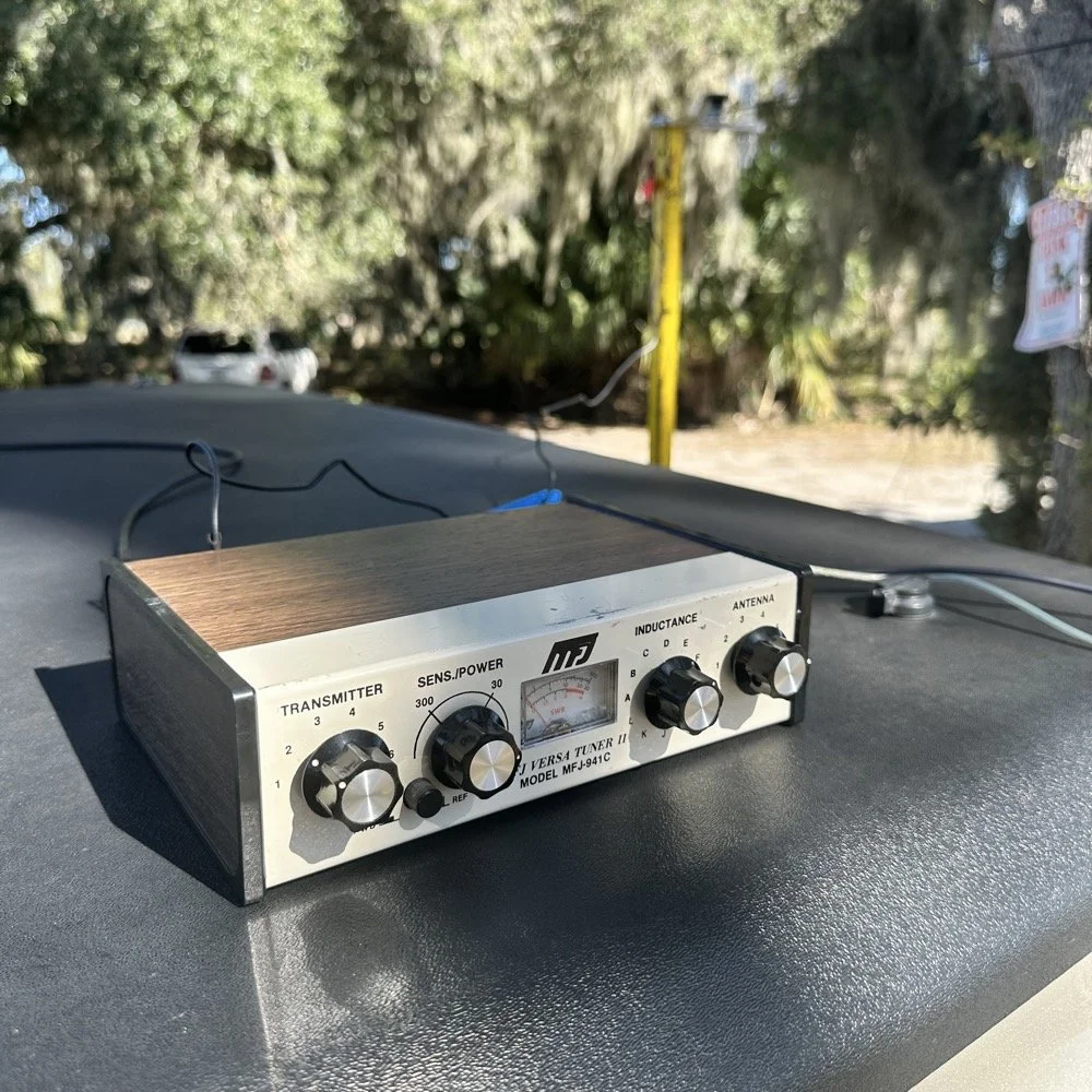
MFJ was a company that some complained about (Surely you have heard them called More Fine Junk) but to be honest, everything I have ever bought that they made has worked exactly as described and was pretty reasonable in price too. I hope someone fills these shoes for the future hams coming into the hobby, this little tuner is amazing for what is in that tiny little housing. It tuned this long wire just fine and didn’t need huge capacitors or inductors to do it. Not to mention it was really economical too. Good kit is hard to find so if you plan to do POTA in the field, I recommend one of these in the box of stuff, it WILL bail you out one day. This tuner has bailed me out a couple of times now…
A throw line, a weight (that I made in the machine shop out of scrap stainless steel) and 65’ of wire made for a lot of fun today.
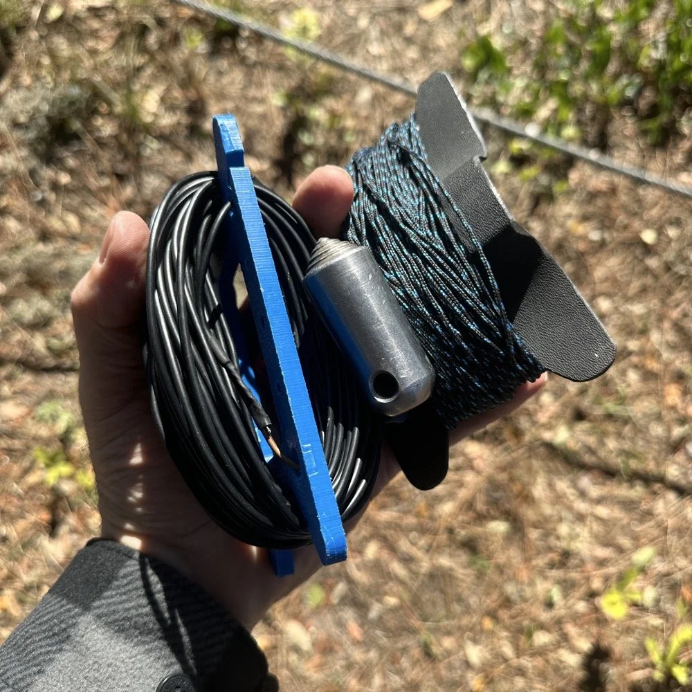
You can’t really tell it in the photos, but I did use my vertical antenna truck mount. I used it as the truck side anchor for the long wire and strung it up into the tree you saw earlier. This turned out to be really convenient I must say.
SIDE QUEST ENDED:
Back to the project at hand…
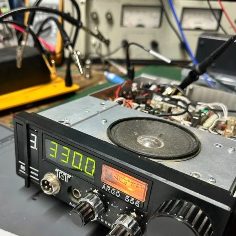
A week later and back in the shop at home with the band module on the work bench again and a Scout 555 in the shop now instead of the ARGO 556 to give me full power (40 watts) into the module (I pull the output power back to 40 watts to help protect the radio).
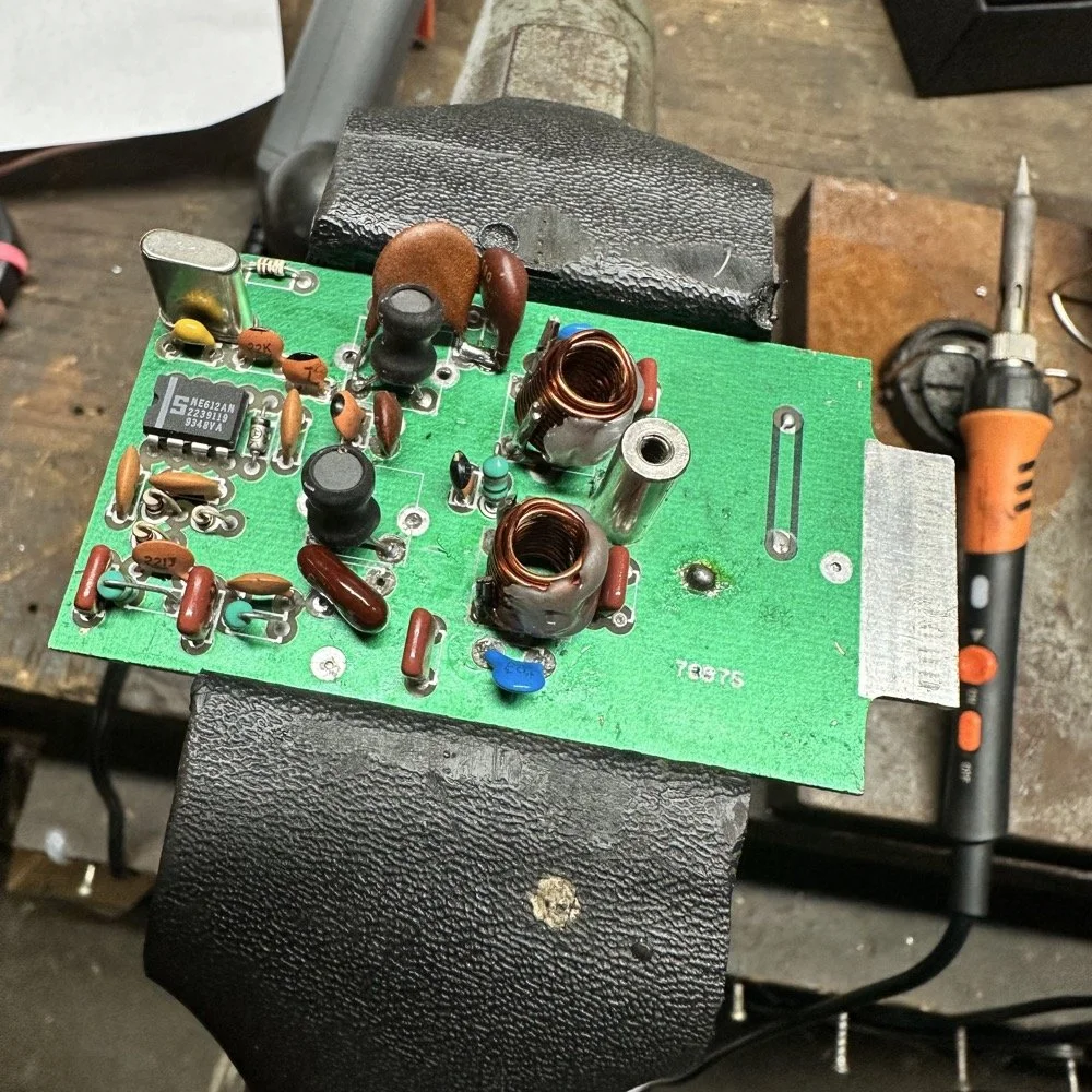
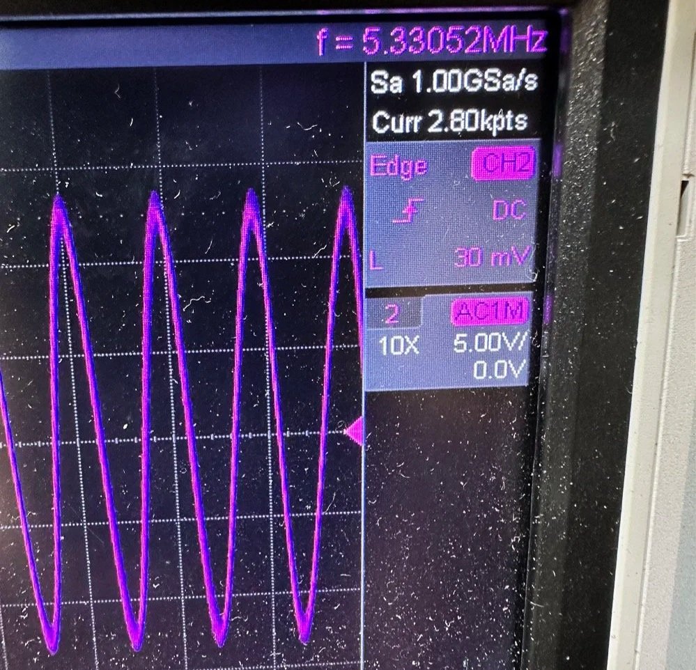
Now I can sort out the last of the details with the filters under full load. I am starting to think that the LO BP filter still needs some work as well as the signal level on the mixer output filter is REALLY high. I don’t remember the exact number but think of something like 700 or 800mV level instead of the 50mV that is supposed to be coming out. I tackle this problem first by building up the board like I had before so I could see the level coming out of the mixer filter. I had removed one of the impedance matching capacitors completely (750pf) without understanding what I had done and this was a big part of the problem with the level being so high. I did some simple math and came up with about 600pF instead of the 750pF that was supposed to be in the board since it was now tuned for 5.35 mhz instead of 3.55 mhz. I ended up using a 560pF cap and the level looked like the photo below on the base of Q16 in the radio. Remember this data is at this link if you need it as NA5N made these wonderful signal flow graphics.
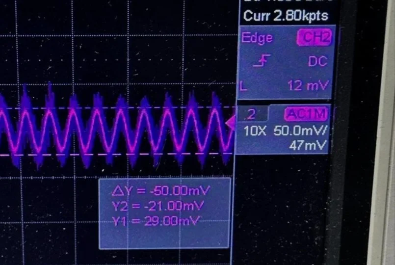
Right on the money at 50mv! I will take that everyday! All the noise you see on the signal is generated in the radio as far as I could tell, all the band modules I tried today looked like this on the base of Q16…or I was picking up the noise from somewhere else, I really am not sure to be honest with you. The output from the collector looked fine though so I don’t know what is happening here. I know this is good now as the frequency in the radio is stable and doesn’t drift. Those NPO capacitors paid off! (NPO means “Negative-Positive 0 ppm/°C” or more plainly, these capacitors are stabilized so they don’t drift in value with a change in temperature) My circuit doesn’t look exactly like the original Ten Tec filter but it does work.
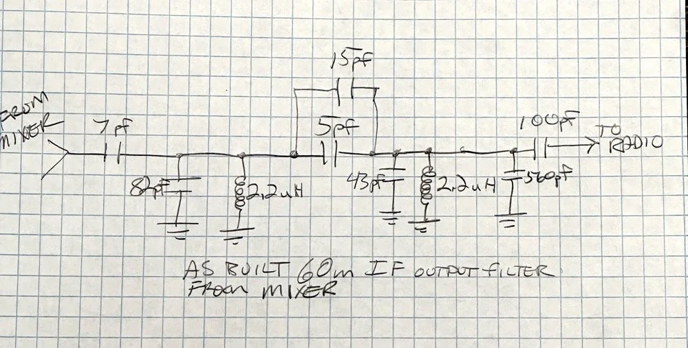
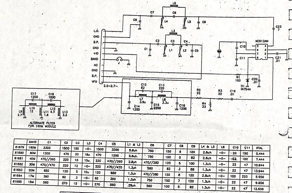
Below is what I ended up with for the filter circuit. I added the one capacitor that was not in the original design (the 43pf cap) and this did seem to help with the shape of the filter so I left it. I drew my filter flow direction backwards from the Ten Tec drawing but you can see the differences from the 80m filter I started with below. Also a couple points of interest here. In my 60m module (formerly an 80 meter band module), the output from the mixer chip is pin 5 on my board and not pin 4 that feeds into the filter network. If you look at the spec sheet, this is fine as both pins are output pins, but it was a curious mistake in the schematic I found while troubleshooting my module. Another curiosity to me is that the schematic shows L6 in parallel with C8 (5pf) in the center of the filter. Not one single band module uses L6… at all. The chart underneath the schematic shows a -0- symbol on each one of the modules for L6, to confirm this, I looked in three different modules and none of them have this inductor in them. It isn’t present on the 10 or 12 meter modules either as they have a different layout for their filters. This was a provision that later was deleted I suppose. Kinda neat to find things like this while doing a project. Makes you wonder why they provisioned for the inductor but never used it. The board has two through holes for the inductor as this is where I placed my 15pf cap (which made adding it really convenient.) So it was obviously designed into the system to start with… Maybe someone who was an engineer at Ten Tec back then will comment.
Excerpt from original Scout 555 owner’s manual.
With that out of the way I moved on to the output LP (Low Pass) filter that the 50 watt power amp flows through to get to the antenna.
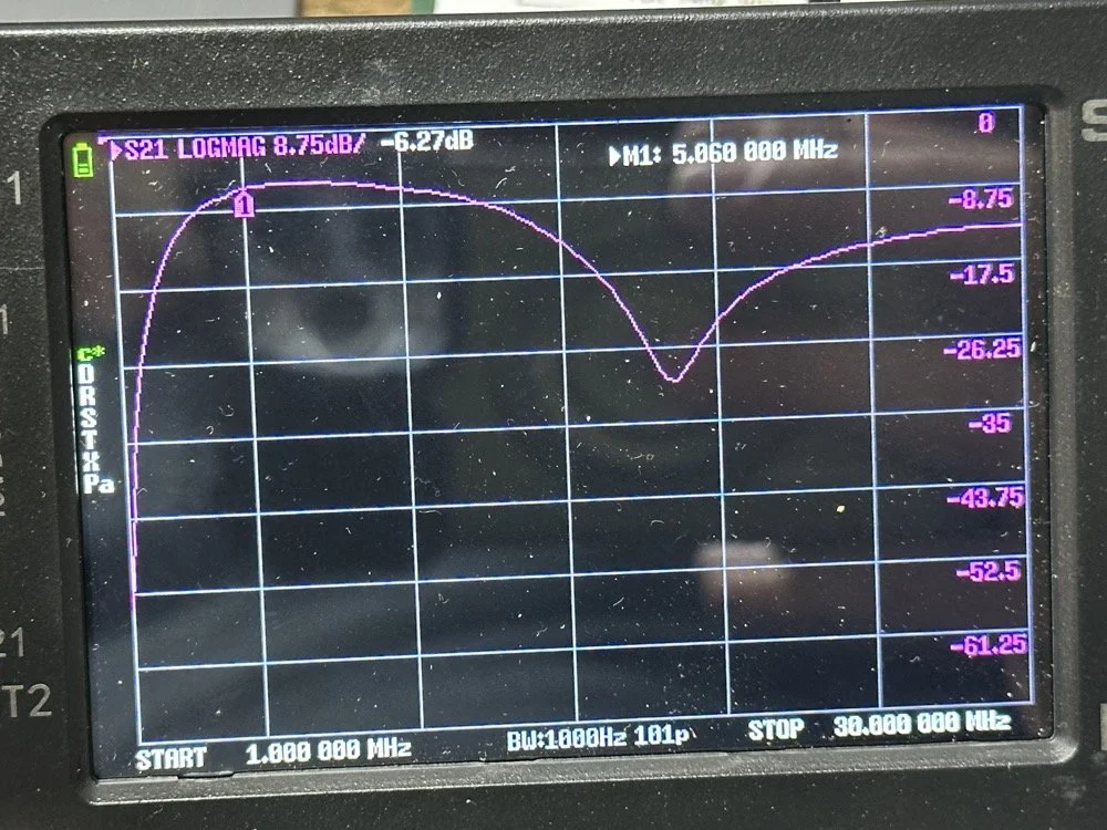
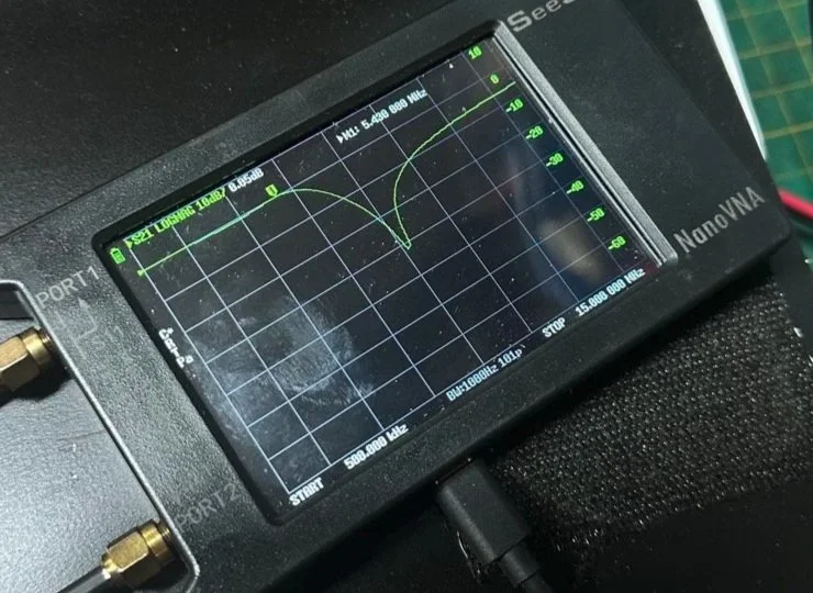
The above photo is of a LP filter out of an unmodified 80 meter band module I used for comparison. If you will notice the roll-off is right smack dab in the middle of the 60 meter band on this particular module.
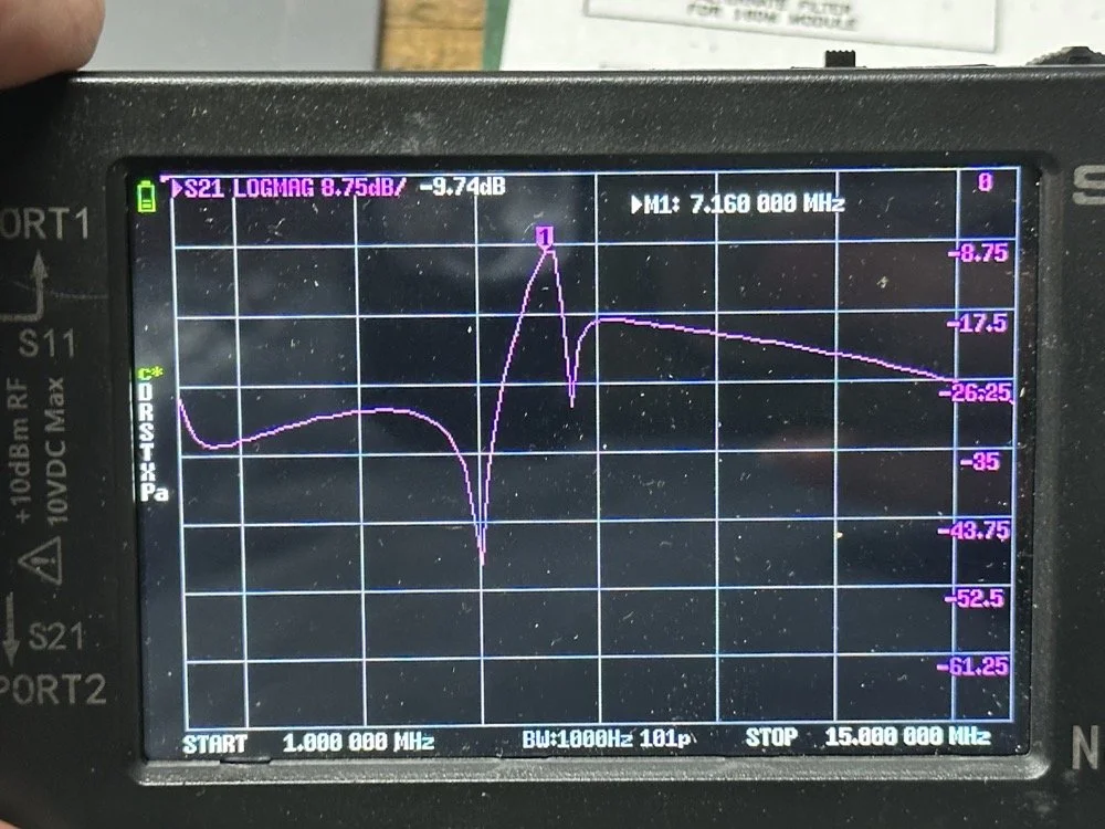
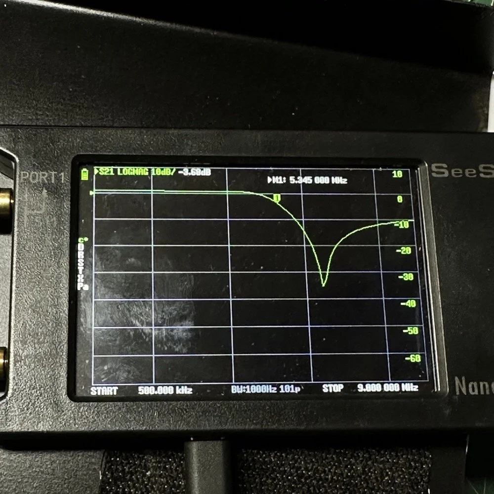
The photo below is of the 60 meter band module sweep that I am building out of an old 80 meter band module. If you will notice I have the nanoVNA set to 5.430 mhz on the marker, and it is hard to see, but the signal is at 0.05dB which is basically zero losses at the highest band position possible. This would imply that the filter would allow the 60 meter band through just fine, but it would not…
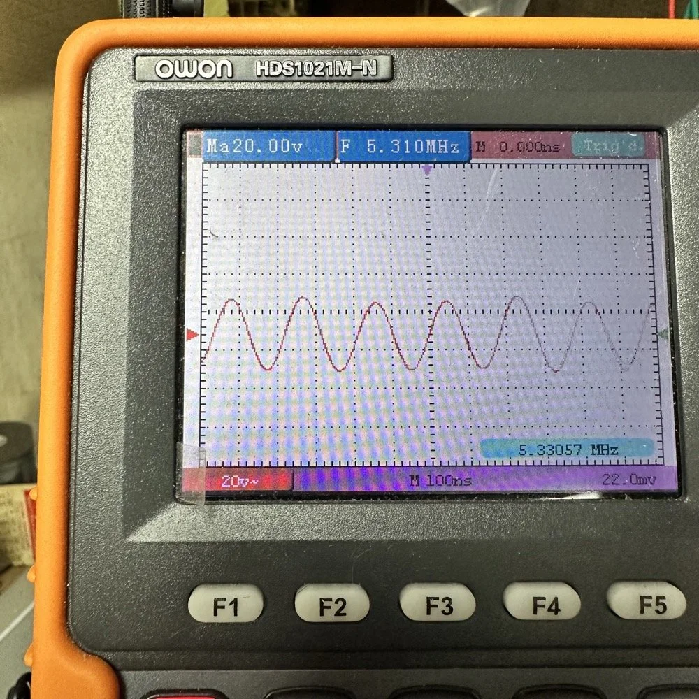
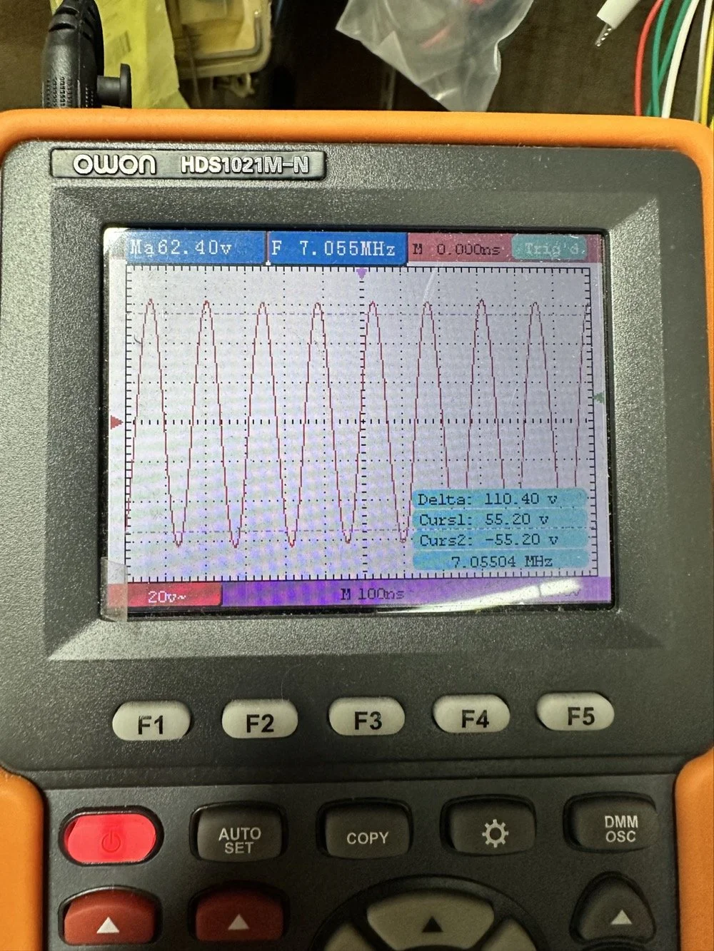
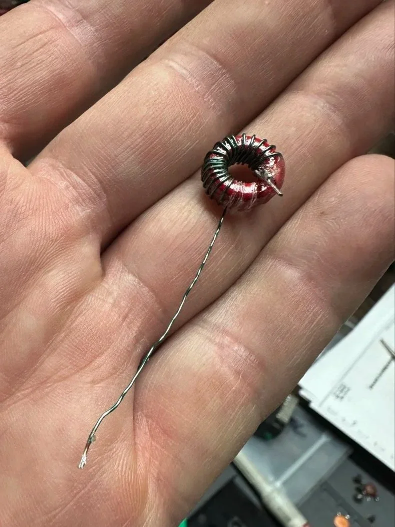
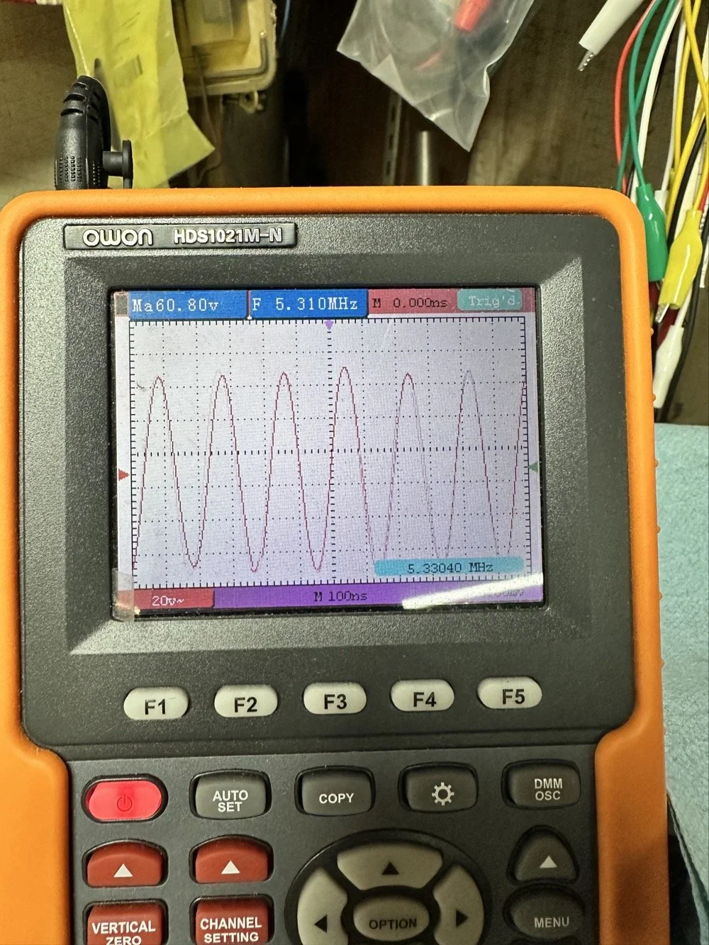
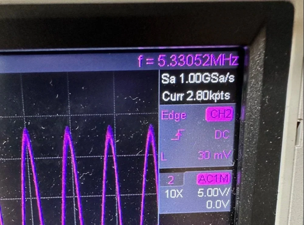
This is what the radio was sending to the dummy load after it passed through the LP filter module (above photo)… So to test this theory, I installed a different module (40 meters) and got what you see below… That is a little over 120 volts peak to peak on 40 meters. Yeah, you don’t change the output power of a Scout without a screw driver so the fact that the 60 meter band module I made is only letting a little over 30 volts peak to peak through it AND knowing that the 40 meter band module is passing over 120 volts peak to peak, tells me the 60 meter filter is choking off the energy and it is probably heating up the toroid inductors pretty good at the same time. I suspect that is what I was hearing the other day at the park when it was crackling after a while. I just hoped that I had not burned the wire on the inductors with this energy… If so I would have to rewind the inductors completely from scratch. Fortunately, I do have a roll of magnet wire I could do it with…
Into the final output LP filter I went (the one in the can) to see what I could do with it. The first photo shows the “can” the filter is shielded inside of to keep stray RF at bay.
The second photo shows what is inside of this can. This is also a photo of my completed filter with modifications to make it work on 60 meters. I found that this module had been tampered with once inside. Now to be fair, I did work on this module at one point to repair a broken inductor lead, but that was all. Now, I am getting much more serious while inside of the can…
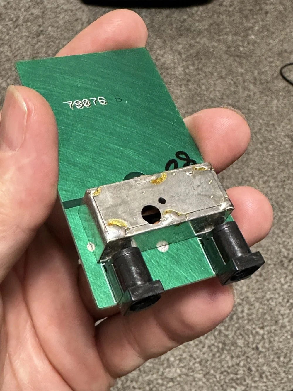
I took another measurement with the nanoVNA and decided to remove the inductors and measure them with the LCR meter to see what it said they were. Turns out they were right on spec from the owners manual chart of 2.5uH each. At least that is what it looked like I read on the meter…haha. So I decide to remove an arbitrary number of wraps from each core (3 wraps to be more precise) and take another measurement to see what I had then. The meter showed them at 1.8 to maybe 1.9uH after pulling three wraps off. This put me right in the middle of 80 meters (2.5uH) and 40 meters (1.4uH) about perfectly. So I trimmed off the excess wire, scraped off the enamel so the solder would adhere to the copper and soldered them into the board.
Back to the nanoVNA for another round of measurements to find it still wasn’t where I wanted it to be. The frequency was still pretty low at the roll-off point. I then decided to look at the capacitors to see what they looked like. This is when I noticed that the band module had already been modified somewhat as the center cap was sitting at about 850pf already and not the 1500pf it was supposed to be. I also found that the two shunt capacitors on the ends were also different from the 80 meter module for some reason. I pulled these back to 470pf each and checked it again and now the band pass was in the 6 mhz area, this should be far enough away from the operational band to keep me from having problems so I put it all back together and then checked it into the dummy load.
Success! I am seeing over 120 volts peak to peak coming out of the radio! Woohoo! I couldn’t believe it! I had full power coming out on 60 meters finally! This was a real special moment for me to be honest with you. After this, I reassembled the shielding on the filter network and cleaned up the solder flux and put the module back together.
With all that done, all that is left is to set it up with an antenna and make some contacts with it…
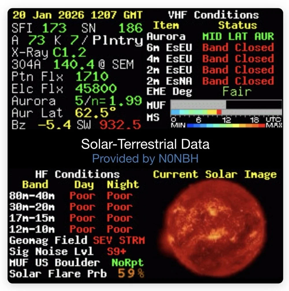
Yeah…about that… There seems to be a major solar storm coming in and has been since the previous day. This is a big deal as you can see from the report. It has shut down radio for most operations. I did call CQ for a while and at one point I heard WY7EE calling CQ but he couldn't hear me. Figures. I did turn up on the RBN so the signal was getting out to some degree in the evening. That was kinda awesome to see as well. I know I have signal going out too as the wattmeter is showing 40 watts forward power. (Remember I de-tune my Scouts to pull some load off the finals since they are getting old and I don’t relish the though of having to replace them for a 10 watt boost in power output) 40 watts will do just as well as 50 from what I have seen in the past… anyway.
The next day we had the storm to start fading out a little and I loaded up the webSDR on my computer and listened for my radio on the Northern Utah listening post. Once the time was late enough, I started hearing my signal on the webSDR! I recorded it and posted it to my YouTube channel as a short if you want to go listen to what I could hear. This is the link.
Link to video about 60 meter signal
Like I said, I am going to revisit the band pass filter for the IF again when I get back into town. I think that can be improved a lot. (my current design is too broad banded in the pass band to make me happy, I want to clean that up some more.) I will write that up when I get the chance to work on it—read Part 4 for the IF filter redesign. Thanks for following along on this little adventure and I hope to hear you on the air at some point. Maybe you will work me on 60 meters with my Scout…maybe…
73 and get out there!
All four parts are here:
- Part 1: Initial Conversion and Filter Design
- Part 2: Crystal Selection and Mixer Circuits
- Part 3: Field Testing and Troubleshooting
- Part 4: IF Filter Redesign (this post)
You can help support this website by using these Amazon Affiliate Links:
QRP/Portable Radios:
Antennas & Tuning:
CW Equipment:
Power & Accessories:
Organization & Transport:
BONUS ITEMS
WK4DS
David
Smith Chart Exploration for Ham Radio: Building Impedance Matching Networks with DIY Inductors
Today finds the unsuspecting ham radio op perusing YouTube for something new to learn as it is really cold outside. He stumbles across a video about using a Smith Chart to match impedance and is intrigued…
What happens next is kinda terrifying…lol
Well to be honest, it is really kinda boring till you see how a smith chart sort of works and you start to learn how to use it to some degree. I have known about them for years, but have never understood how they work or even how to read them.
Today finds the unsuspecting ham radio op perusing YouTube for something new to learn as it is really cold outside. He stumbles across a video about using a Smith Chart to match impedance and is intrigued…
What happens next is kinda terrifying…lol
Well to be honest, it is really kinda boring till you see how a smith chart sort of works and you start to learn how to use it to some degree. I have known about them for years, but have never understood how they work or even how to read them. The other day though I landed on a video. This one shown below to be exact and I was hooked.
As you can see, if you watch this video, (maybe a couple of times), he explains it in simple enough terms that I actually understood what was going on finally! I did come into it with the understanding that the upper half was inductive and the lower half was capacitive from tuning my antennas with the nanoVNA. I would leave the smith chart on out of laziness and simply used the SWR graph to move the null to the operating frequency. But during this time, I started looking at the information presented on the display and noticed at times it would show capacitance and sometimes it would be inductance and also where the marker was sitting. This gave me the clue about what it was sharing with me. That was the extent of my smith chart knowledge though. At least it made sense to me. So the next logical thing to do was to order some smith chart notebooks from Amazon and a drawing compass so I could use said charts. While I was anxiously awaiting the new goodies to arrive, I started binge watching videos on smith chart use and taking away what I could from each video to add to what I already knew. By the time the paper arrived (I know I could have printed them off the web but the notebook format is really nice to be honest) {sarcasm}I was already a “master” at these “simple” charts… haha. {/sarcasm}
I will be honest with you. There is so much about these charts that I still don’t understand that it boggles the mind, but I have figured out how to use them for impedance matching and it is kinda awesome. I actually made the last few pages in my new notebook a cheat sheet based on the above video so I could reference it easily without having to watch the video over and over. I am absolutely going to build one of these fixtures when I get back home too. I would already have done it but I am not able to access my bench to put it together… So what follows is what you do when you don’t have that gear handy.
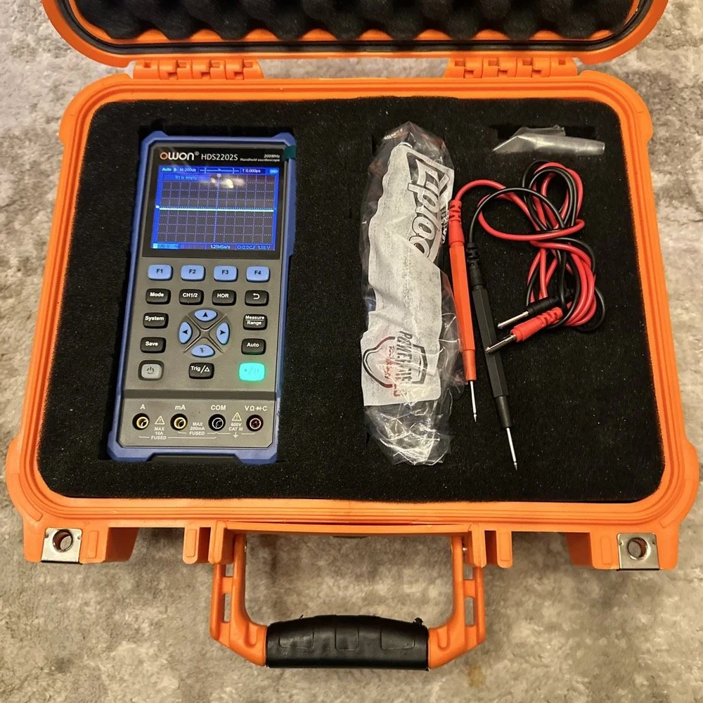
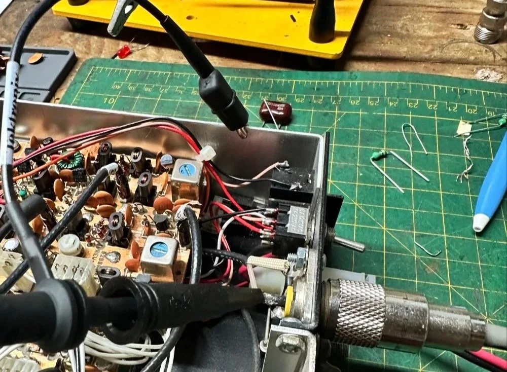
First things first, I bought a new toy. This is a 200 mhz “scope meter” but this one has another trick it can exploit. This is a actual dual channel oscilloscope AND it also has a arbitrary waveform generator as well! On top of the usual multi-meter functions as well. This thing has a lot to offer…till it doesn’t. It didn’t take long to figure out that the waveform generator doesn’t have the sweep function in it, this would have been nice to play with things. I can’t find FFT modes anywhere in it either so it can’t be a “poor man’s spectrum analyzer”. The little meter does have enough options to be really useful for what I was doing anyway so let’s get started… oh, it doesn’t come in this nice hardshell case. This is an Apache case from Harbor Freight. It is the perfect storage container in my opinion and I am happy to have it trimmed out like this. It didn’t take too long to figure out how to use the oscilloscope and I made a cheat sheet for it too so I can access useful features more easily in the future since a lot of it is hidden in menus due to the diminutive size.
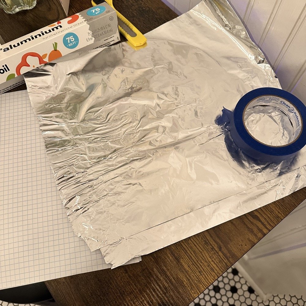
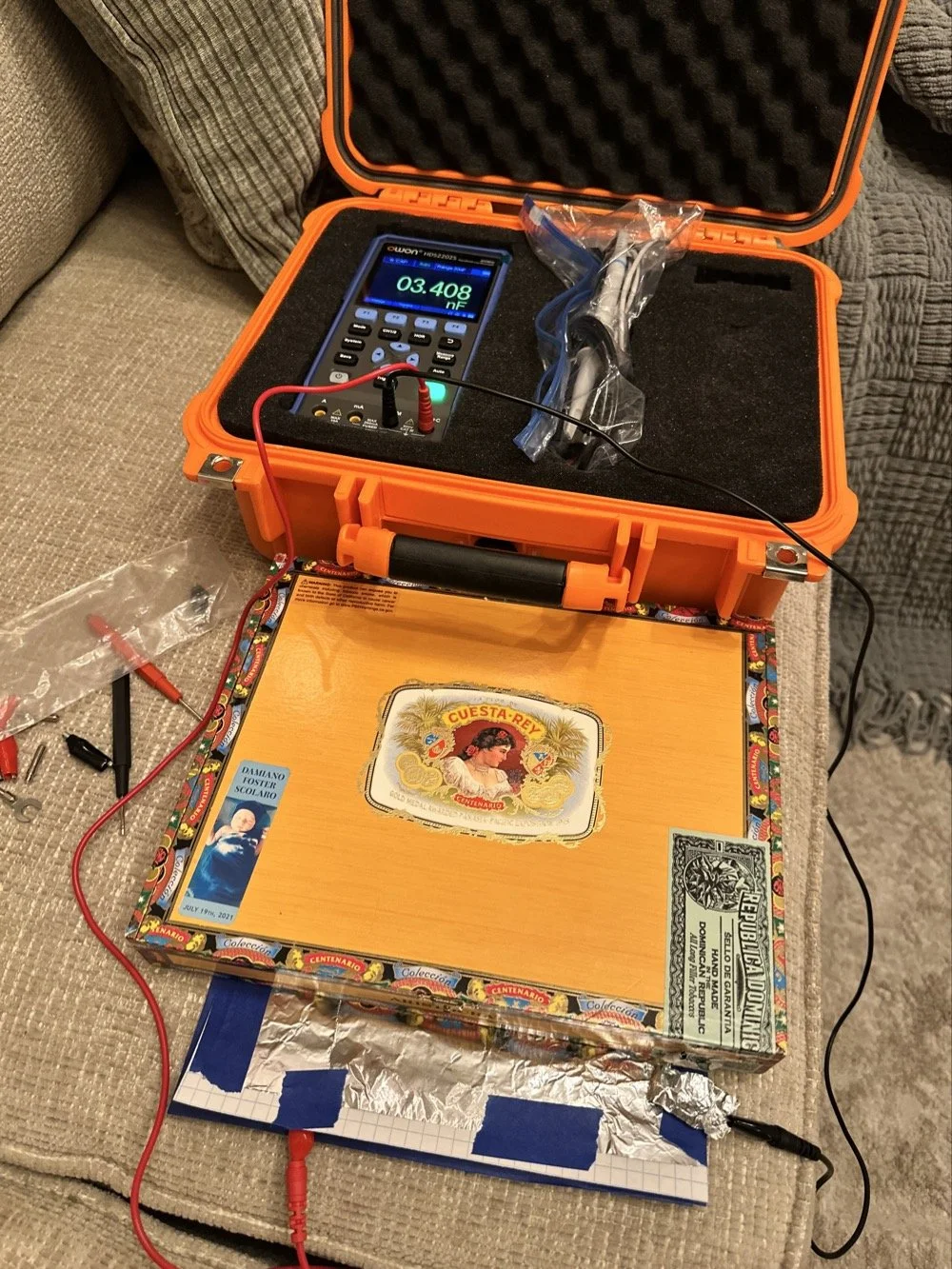
What you see here is pure desperation to see if I can make this smith chart stuff work for me. I am literally about to start making capacitors out of aluminum foil, a sheet of notebook paper and painters tape… Spoiler alert, it worked… You see, in another video I found on YouTube, there was this idea that you don’t need a LCR meter to measure your components as long as you have a known value device, a battery and some ingenuity. I also had a lot of time to play with this concept so here we are… I started by making a really big capacitor to start with to do a proof of concept and to see if there was enough capacitance to make this project work. Turns out there was way more than needed with the initial design, WAY more. So with the proof of concept made from three full size sheets of paper laminated with aluminum foil on one side of each one and then stacked so that the center sheet was one plate and the top and bottom were the opposite plate, I found I had made a .0034uF capacitor! This was more than enough to play with HF radio RF frequencies!!! Woohoo! Now this is all based on me being able to believe my new meter and later I find out that there is 17pf of stray capacitance in my meter and leads. Once I figure this out, and factor it into my math, it is all good but for now with this thing being 3408pf, I don’t think it is really a problem. The cigar box is there to use gravity to apply an even pressure to the “plates” and hold them at a consistent spacing as at this point, these were just three sheets stacked up. The top and bottom are connected to the black lead and the middle one is connected to the red lead. Also tested it with just on plate on the black lead and yep… capacitance went WAY down, so this style of capacitor worked pretty well to be honest. I could make it go up a good bit more by pressing on the cigar box too, I saw 5.0nF at one point while playing with it, that is crazy to me…
I had read somewhere about this idea to be honest. Well a cruder version of it actually. They made an impromptu antenna L network with two sheets of aluminum foil and a sheet of news paper or something like that. That made the capacitor and the inductor was wound on something found commonly in the house in the 1960s or 70s as well. They just used regular old romex house wire to make the inductor and it also worked just fine. Sometimes you just really need to have some “want to” and it can be done. I was a little more superfluous with my build as I didn’t need it to get on the air but rather as an experiment to see what I could learn.I honestly was really surprised to see how much capacitance I could get out of notebook paper and aluminum foil from the grocery store. This tells me that literally anyone that needs an antenna tuner, has one if they want it bad enough. You don’t have to have a Ten Tec 238 to be able to tune that random wire, you just need to gather some stuff you probably already have in the house…
Side note, I also finally acquired a new case for my POTA Scout 555 radio. I still need to finish the pockets for the band modules when I get home, but I now have it in a proper case and not just sitting in a cardboard box in the back of the truck! Also, I made another 60 meter contact today… to the same exact person that I made the first one with a couple weeks back! HAHA! I think we are the only two people on 60 meters CW in the mornings ever…
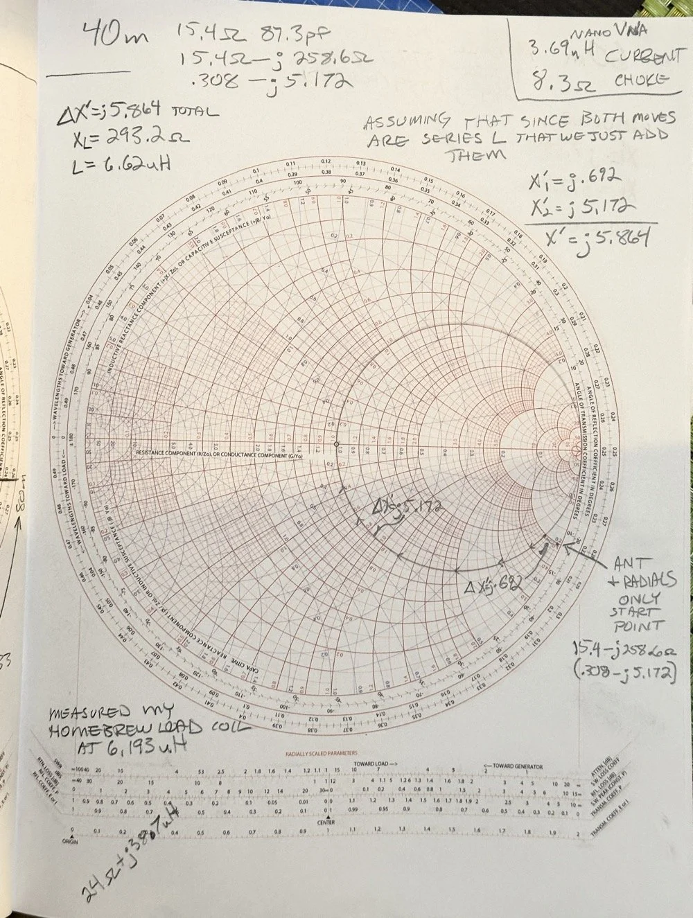
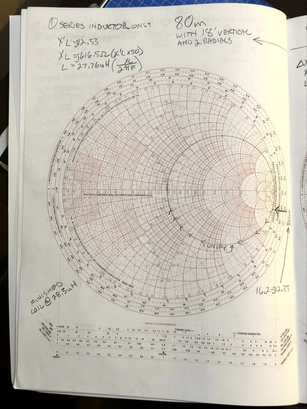
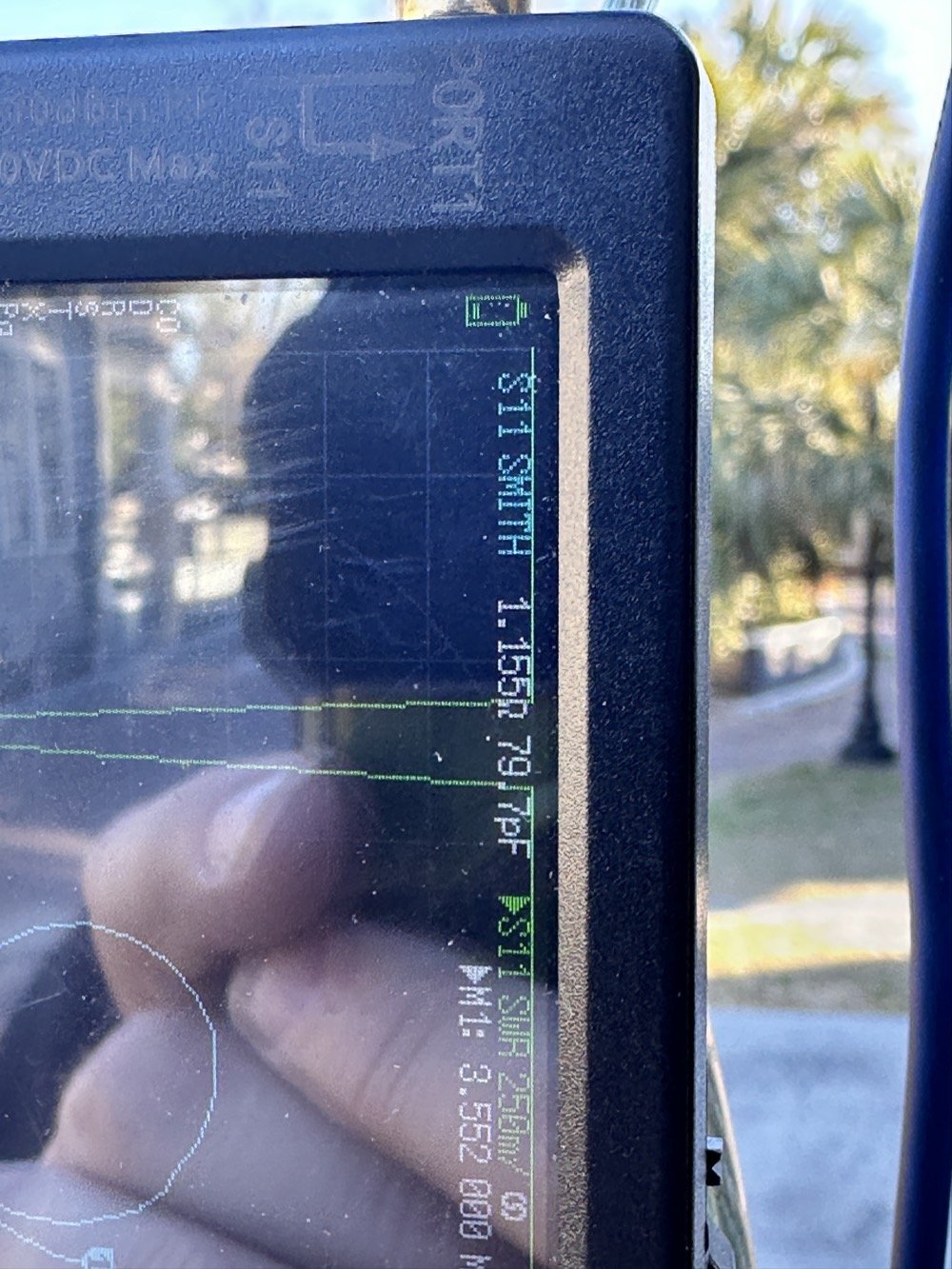
Here we see what I measured the other day while at a POTA park. What these numbers show is the antenna measurements for the band at the base of the antenna. I literally took the nanoVNA and adapted it to the antenna socket directly to eliminate the 50 ohm feedline from interacting with the measurement. As we will learn soon enough that you can use a piece of feedline (coax in particular) to move the base value around the smith chart should you need the starting point to be somewhere else. But I also learned something else about these starting point numbers below that I will share with you in a little bit.
At the top of the page, right next to the “40m” is what the nanoVNA reported that day at the park. (15.4 ohms and 87.3pf) you have to have two coordinates to plot anything on a chart so these are the two numbers you need to plot your starting point. Ignore the other notes as I am probably wrong on some of it and it actually makes more sense later. But the first thing I had to do was to turn these numbers into the proper numbers that the smith chart uses. This is called normalizing them. You see the chart is relative, you can assign whatever value you want to the center point on the chart and the rest of the chart is “relative” to this value. So if you were to work with 75 ohm coax and wanted to make an impedance matching network to work with it and having minimal losses, then you would assign 75 ohms to the center point. Since we use 50 ohms in almost all amateur radio (if not all) then our value is 50 ohms at the center point.
So here is my 80 meter plot (below) to get to a 50 ohm impedance from where it started at… yes… 1 ohm and 79.7pf capacitive! You see I am designing a matching network to couple my 50 ohm coax to a 18.4 feet tall telescoping vertical with a couple of radials thrown out on the ground. This is not even close to a matching antenna for the 80 meter band at all. Hence the terrible numbers to start with. Well, this was like those jokes you here from high school where you get something simple in the lecture in class about a subject then in the book it might show it with one more complication but the exam shows the Drake equation for the problem on the test! Well this is what happened to me as in the video above, the number in the video was closer to the middle of the lower half of the chart making for a more straight forward solution to the problem. I also did my admittance math wrong too if I am right…lol… since it is all inverted, but this doesn’t matter at this time. What you need to know at this point is that my problem lies outside the unity circle (that is the one I drew on the chart) and I need my “arc of movement” to cross this circle… it does but nearly at the infinity point (on the right side of the chart) which makes the math almost worthless… The reason the math gets pretty inaccurate is the numbers on the chart start getting logarithmic is value and so a small movement on the chart in this area makes huge changes in the values. You want your plot point anywhere else but here, yet this is where I am at in this blog post… haha
Knowing all this, I start this complicated, 3 position move to get me to the center of the chart. Mind you, I think this would actually work, but I am not sure if the math is mathing right at this time. (I am thinking the first move is a piece of transmission line to move the start point around the circle instead of an inductor and the second movement is also not a capacitor either so basically this whole thing is drawn wrong…lol) You will see why in a minute too as to why I dont know. The schematic for this movement is scrawled in the upper left hand corner of the notebook page if you wondered what it would look like to make this circuit. Two inductors and a capacitor to get to 50 ohms… how many antenna tuners have TWO inductors in them? I will help you out here… not many, if any. The number of inductors alone would make this a no go design for the most part unless is was going to be a one band wonder. Just remember I am pretty sure the math on this is wrong, the plot directions are correct, but I am thinking that the suseptance values are needing to be inverted to calculate the impedance for the two movements on the blue lines. Anyway, the point of this blog post is to show what is possible if you want to learn something new and it is not about the math around a smith chart…yet…lol I am diving back into the tutorials to figure out the blue part of the chart next.
After I pulled my hair out for a while…wait, that don’t apply to me…I’m bald already… After getting over the frustration of trying to solve this problem, I redrew it on a fresh page and looked hard at it for a minute and had an epiphany… The plot point is not INSIDE the circle, or even anywhere closer to the middle of the chart at all, which would have been ideal, BUT it is really close to the unity line already. I mean REALLY close, so close in fact, I bet you could simply run around the unity line clockwise to the center point and just “eat” the misalignment on the horizontal resistance line of such a tiny amount and no one would even notice in the real world. You know what this matching network now looks like? A huge by large inductor is what, just a plain ole gigantic coil… Moving clockwise around the impedance lines (the red ones) indicates adding inductance to solve the problem. This is what all the antenna companies use when you buy a mobile 80 meter whip antenna if you think about it, just a huge load coil and nothing more. If you were to zoom in on this, I am guessing the resistive value when you get to the end of the arc, at the horizontal center line (which is the pure resistance line) would be something like 49.2 ohms or something close to that, literally less than 1.1 : 1 SWR maybe less to be honest.
Armed with this knowledge, I wanted to test this theory. So I now needed a way to make a coil to insert between the feedline and the base of the vertical to see if I had learned anything. Well I had this new scope / meter / signal generator widget and I had a way to make a capacitor, I then remembered a video where I guy showed how to measure inductors and capacitors with only a oscilloscope if you have one known device. Well, I have a capacitor that I made and I can measure it with the new meter, so that will give me the “known”.
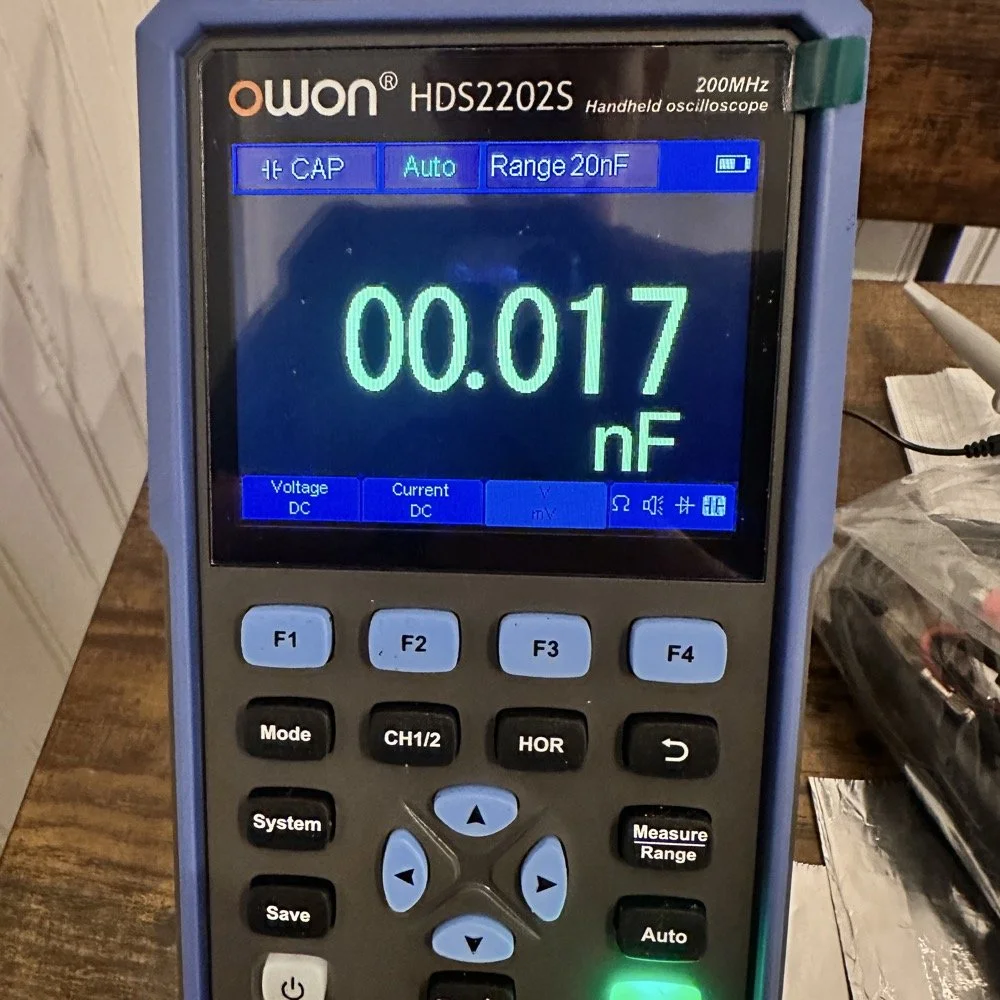
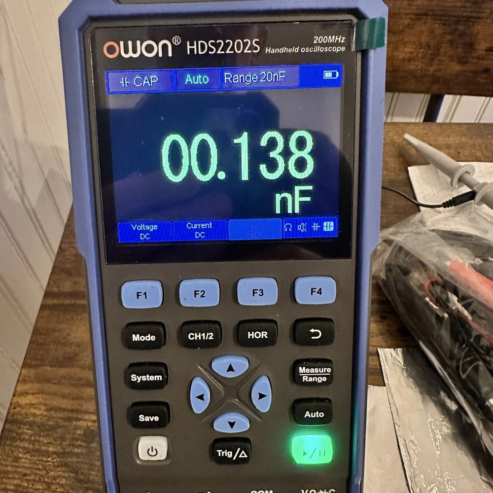
So I fire up the new meter and plug in the leads and find this. There is no way to “tare” out this number either so you simply have to subtract it from what ever you measure. I figured this would be pretty easy so I just went with it. Below is a photo while I was trimming the capacitor to a size I wanted. I was looking for 100pf and as you can see below on the meter, I was getting close. This is measuring right at 121pf in the photo. I would trim off the edge of the sheet and then check it again, rinse and repeat till it was close to what I wanted.
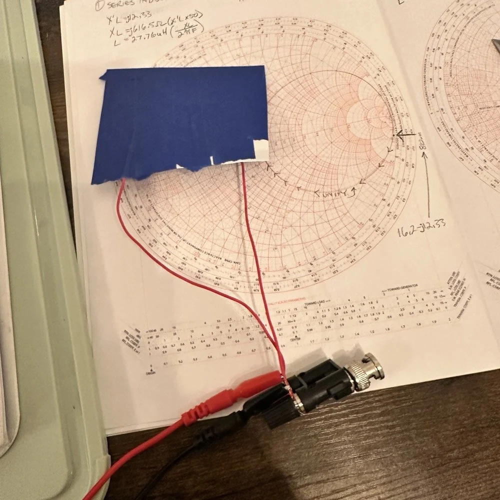
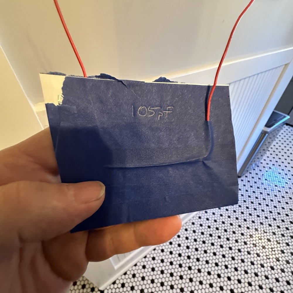
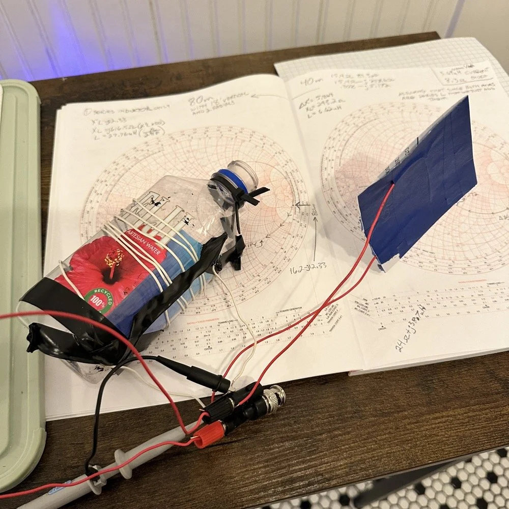
Once I had my brand spanking new capacitor made and trimmed to size (105pf), I setup a test fixture to do my test with. The test fixture is also expedient since it is all that I had was one of those “BNC to binding post” adapters and just used it as a sort of bread board to attach all the parts to the system. It worked, it was pretty janky, but it worked. All that we have here in reality is a parallel tank circuit. It will resonate at one frequency natively and I can measure that and then use a simple online calculator to see what the inductance is based on my capacitor value and the frequency of the tank circuit. How do I get it to resonate then? Simple, use a battery…
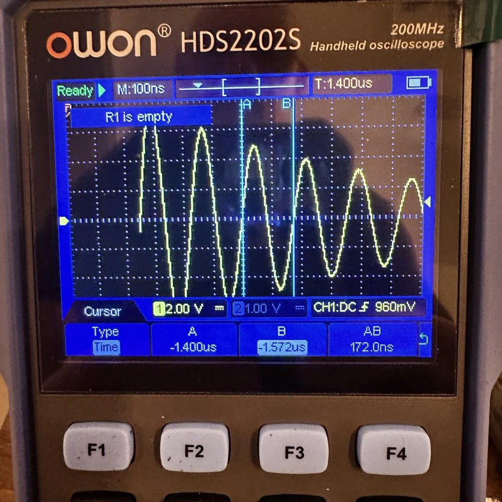
In the other video I had recently watched he showed simply setting the scope to trigger off of a voltage level close to the value of the battery which will allow the scope to capture the ringing of the tank circuit if you pulse it with a battery. I just took a AA out of my pocket flashlight and used it, set the trigger to normal and set the trigger level to about 1 volt and started touching the battery to the two red wires going out to the left in this photo below. This biased the tank circuit (simply applying a dc voltage across the capacitor and charging it) and I was rewarded with what you see below on the scope in the below photo. To be perfectly honest with you, I had done so much wrong in this process that I was honestly surprised that it worked. I even had to show it to Teresa and she had literally zero idea about what she was seeing here, but I had to show SOMEONE that it has actually worked!
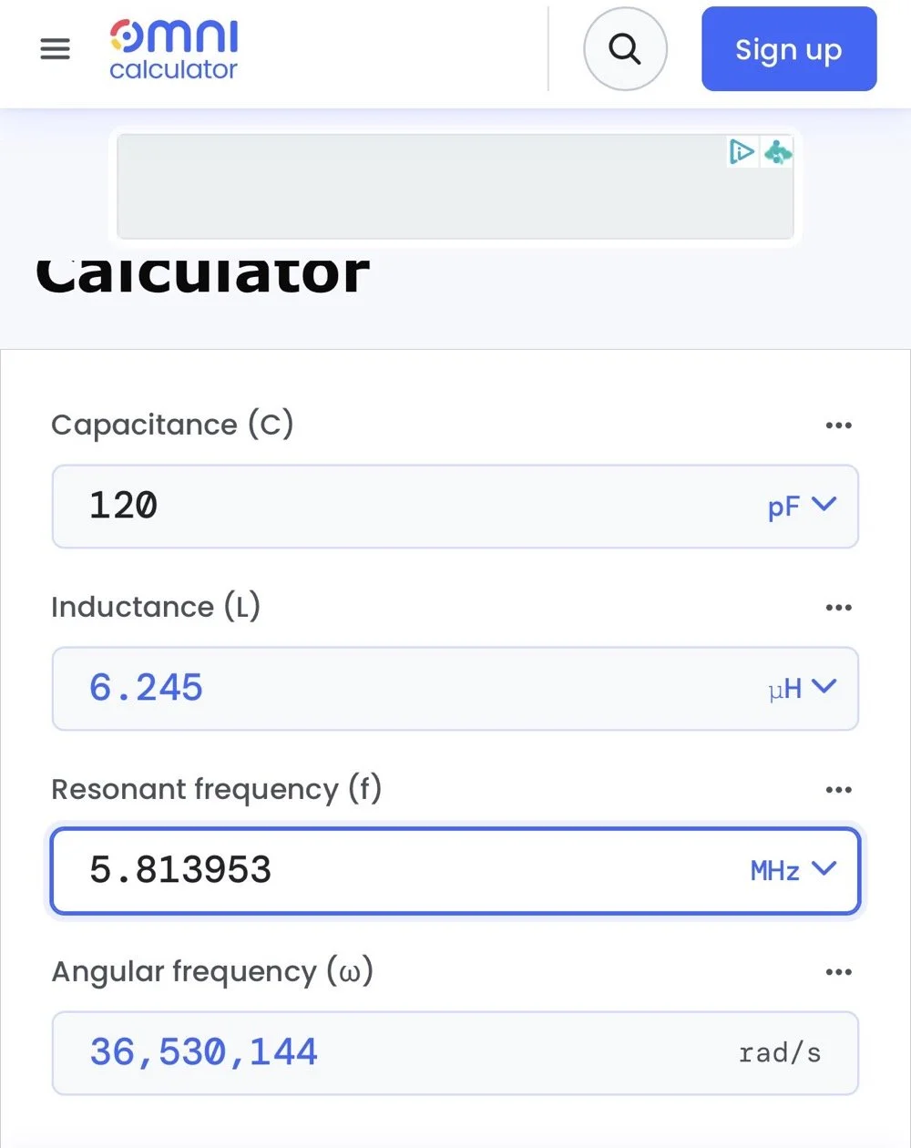
The ringing the scope captured is nice and clean and I was able to measure the period of the sine wave at 172 nanoseconds. Transforming the time into a frequency is easy, you simply invert the number or divide 1 by .000000172 and you get 5,813,953 hz. This frequency is not relevant to the ham bands but is only useful in telling us what the value of the inductor is, which is what we want anyway. As you can see from the screen shot below, this inductor is 6.245 uH (micro henrys). I did the plot on the smith chart for 40 meters for this antenna and came up with almost exactly this number, I came up with 6.62uH on the math. This also makes sense as I did this physical coil for the 213” (17.75’) WRC vertical and not this one that is longer that I am using now 221” (18.4’). Another possible reason for the variation from the measured and the plotted values is that my capacitor value could be slightly different from being moved around or being in proximity to metal or some such. You could touch the capacitor with your finger tip and the value would change so this is probably part of the variation…
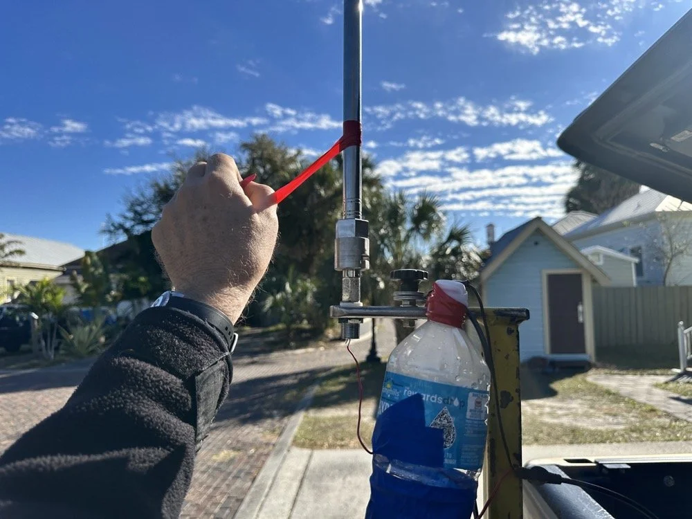
I made this actual load coil by guessing to be honest, I did use the nanoVNA as a SWR meter when I made it and I would take off a coil or two and measure it and I simply walked the null in on the antenna for 40 meters that day. Now I know how to use a smith chart to do that math ahead of time. That is pretty cool.
Literally using trash to resonate as a tank circuit is kinda cool to be honest with you. The wires for the capacitor are simply taped to the aluminum foil, nothing more as I didn’t have a way to solder them together or anything like that. This was truly a temporary test fixture for experimentation.
The next logical step was to make an inductor for 60 meters and to hook it up to the antenna and measure it with the nanoVNA to see how close I could get it. This is where things started to go south…
First of all, I had problems replicating the same resistance and capacitance from that day at the POTA park. The photo of the VNA above shows what I am talking about. Now it is 1 ohm… yeah basically a dead short for the RF. But more importantly it is different from the day of my test which was about 10 ohms (if memory serves me) but basically this doesn’t matter when you get to the region of the smith chart that this plot is landing in. The capacitance is what really drives this position between these two numbers and it was virtually the same. The amount of inductance will be more for 1 ohm but not a whole lot more.
Well what happened when I hooked up the coil and the vertical and stuff in the driveway was a whole bunch of nothing! It just made a circle around the outside of the smith chart, which is bad if you don’t know. You want your line to go through the center of the chart at the frequency you want to use and if it goes around the outside it ain’t going through the middle!
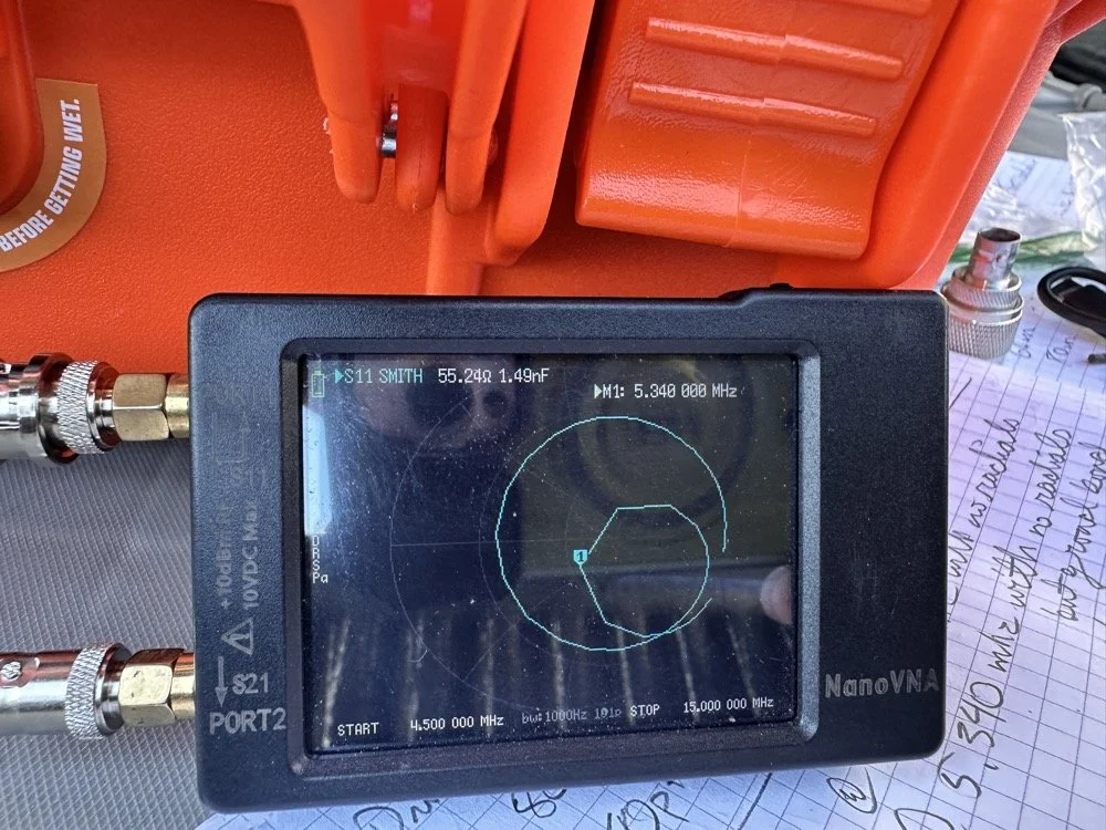
Deflated that I had probably done all that math wrong…again… I was about to throw in the towel when the wind blew and the plot on the nanoVNA moved towards the center! What just happened??? I start messing with this and that, as you can see in the photo above that the coil output wire is just poked into the coax port on the antenna. This has to be the worst way to make this connection, but if this is all you have, then this is what you do…
I could grab the vertical and that would make drastic changes to the smith plot, so I thought about moving the antenna without touching it and I found a roll of electrical tape and used that to tug on the vertical as it is in a QD mount (which is not a great connection to be honest that I have found). I even cleaned some stuff to no avail, but when I put the tape on the antenna and pulled it in certain directions, I would get the plot you see below. Notice the marker is at 5.340 mhz and at 55.2 ohms and just 1.49nf capacitive. This is less than 1.2 : 1 SWR and I am sure that it is off a little because of the system losses at this point. All the loose and dirty connections along with the random radial placement (I find this makes a pretty large difference with my systems) made getting repeatable results almost impossible. This told me that the coil worked though and that my math was not wrong! I had actually learned something here!
Once I figured this out and took a couple of photos for the blog, I tore the system back down and put it all away so I could get started on this write up about it. This has been an amazing process to do this and I learned way more than just how to do impedance matching with a smith chart. I learned that my system is way too inconsistent to simply make a coil and expect it to work in the system. If I had all the parts hard mounted in place with corrosion inhibiting paste on the connections then I could calculate this coil and it would drop right in. I was blown away by this and cant wait to find another use for my smith chart notebook. I hope this has helped you in some way either by simple entertainment or by learning something about smith charts and antennas, or maybe that there are YouTube videos about how to do this sort of stuff, either way, thank you for reading to here and I hope you come back for more of my ramblings in the future!
You can help support this website by using these Amazon Affiliate Links:
QRP/Portable Radios:
Antennas & Tuning:
CW Equipment:
Power & Accessories:
Organization & Transport:
BONUS ITEMS
73
WK4DS - David
![Building a 60m Band Module for Ten-Tec Scout 555: Crystal Selection & Filter Design [Part 2]](https://images.squarespace-cdn.com/content/v1/5d17806ce65eba00011667cb/1768486316134-5KK47YMDB3P45BK25B4N/IMG_1141.jpg)
Building a 60m Band Module for Ten-Tec Scout 555: Crystal Selection & Filter Design [Part 2]
I figured the the mixer’s bandpass filter would be the same as the IF filter but turn’s out I was wrong here. I looked at the existing part values on the chart for 40 meters and 80 meters (remember that part about not having a formal education in this stuff?) and simply decided that the inductors were again too big and I needed them to have a slightly lower value instead.
Well, if this is the first post of my blog you have found about the 60 meter band module, please Read Part 1 for the complete background on this project. or a lot of stuff is not going to make sense…haha.
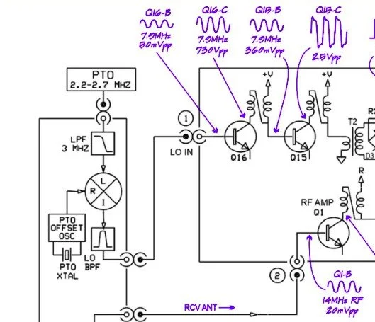
The donor about to undergo surgery to become a 60 meter band module.
As you know from last week, I was able to get all the filters updated except the output bandpass filter for the mixer and changing the crystal, so let’s get into that today.
I figured the the mixer’s bandpass filter would be the same as the IF filter but turn’s out I was wrong here. I looked at the existing part values on the chart for 40 meters and 80 meters (remember that part about not having a formal education in this stuff?) and simply decided that the inductors were again too big and I needed them to have a slightly lower value instead. This is where things get engineery..is that actually a word? It should be. I started by simply using an online calculator to figure the values for this filter based on the chart from NA5N’s Website and my own simple math of a mixed product of 11.442 mhz. It falls right in the middle of the 80 and 40 meter LO frequencies on his chart. So now I needed a crystal…
Luckily I didn’t need matched sets like when making a crystal ladder filter so I was able to find 9.218 mhz crystals on Digikey for reasonable money. The calculated crystal frequency I came up with was 9.242 mhz to land at 5.300 mhz. This radio will absolutely transmit out of band and it is the responsibility of the user to stay in legal band space so I figured this would cover the entirity of the 60 meter band. The NA5N chart shows the PTO minimum frequency is 2.2 mhz so that is where I started my math.
2.200 mhz (PTO min.)+9.218 mhz (PTO XTAL)=11.418 mhz (LO) - 6.142 mhz (IF) = 5.276 mhz
The entirety of the 60 meter band is from 5.3305 mhz to 5.405 mhz so this will work perfectly fine.
All this math starts to make sense when you look at the chart at the bottom of this page. That is why I keep linking it…haha. So I build out the band pass filter and install the new crystal when it comes in and … nothing… Well, it did something actually. It would not lock onto the frequency at all, it would attempt occasionally, but most of the time it would just scroll numbers on the display of the radio. It obviously was not working. I was sure I had built the filter right… (turns out I was dead wrong…again…I am starting to see a pattern here…haha).
As I would soon find out, I built the filter for the 40 meter IF by accident. At this point I had a lot of numbers floating around in my head and scribbled on various pages laying around the bench and one was where I had done some of the math around the 40 meter circuit for some reason and I inadvertently used those numbers to make the inductors with. Couple this with a trip out of town for a week and you will see where I lost my train of thought. Once I returned from the trip I had just two days before leaving again to see what I could figure out.
Well, this is what I figured out.
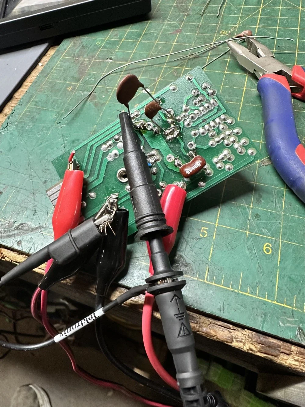
What you see above is a frustration point to be honest. I studied the print long enough to realize I could bring the circuit to life if I had a signal generator and a power supply. To get this to work I soldered several small scrap clippings from component leads to the board in strategic places to be able to connect leads for various devices and you get what you see above. I immediately went down a rabbit hole on signal generators and ended up with a UNI-T UTG962E and it arrived THE DAY BEFORE WE LEFT ON OUR TRIP. I get it going and power up the circuit with the 10 VDC bus and then inject a 2.2 mhz signal from the brand spanking new signal generator into the line (simulating the PTO) to see what I would get at the output… well… nothing. I checked the crystal and I had a clean 9.218 mhz signal at about 700mV going into the mixer chip but my 2.2 mhz injected signal was 50mV (the signal level based solely on the output shown on the block diagram going into the receiver control board as the data sheet for the chip I found didn’t show a signal level threshold that I could find.). This was obviously too low and I started turning up the signal generator and nothing happened at first. I was at 700mV of signal level coming out of the generator and I was getting nothing at the output of my filter. So I start walking it back to the output of the generator. I didn’t have anything at the output of the mixer chip as it turned out, so I check the inputs to the chip on the chip directly and the PTO input was almost non-existent. Turns out that the output impedance of the signal generator and the input impedance of the low pass filter for the mixer chip on the board must be different as it was dropping the level pretty dramatically. (This is something else I have learned while doing this project, you have to observe the impedance between stages or it wont work. ) So what do I do to solve for this? (Remember again I have almost no formal education in this area of expertise) I simply put the scope on the output of the mixer IC itself and slowly start turning up the 2.3 mhz amplitude till Eureka! The mixer sprang to life and I had a product!
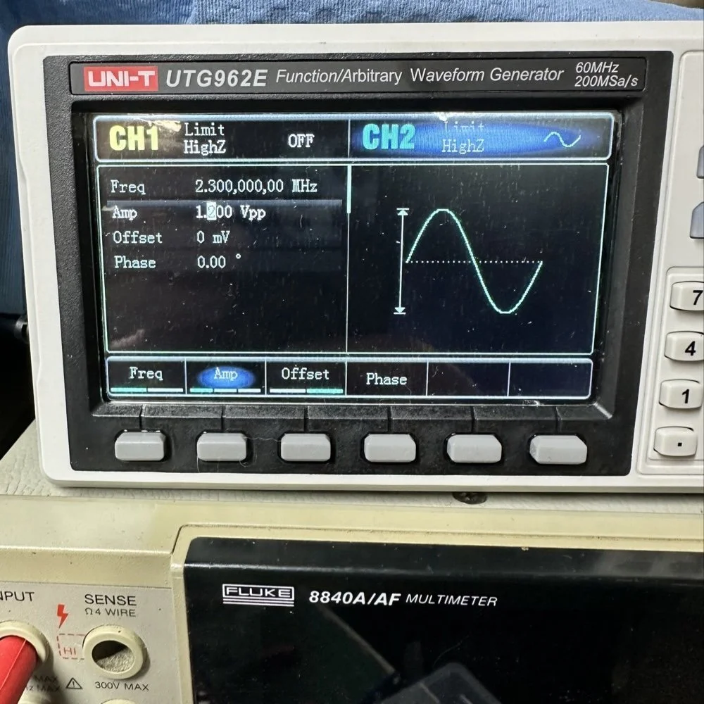
Note: I am using a different value here for the PTO reference signal because I didn’t notice that I had changed it till I got the mixer working. But it is fine as the PTO operates from 2.2 mhz up to about 2.7 mhz anyway. The key was getting the bottom of the mixed product below 11.425 mhz when the PTO is at minimum. This will allow tuning through the 60 meter band. But this is why the number in the photo below is 11.520 mhz and not 11.425 mhz.
Now that I have a signal coming out of the mixer IC, I need to see what it going to the receiver control board. You see on the signal path drawing from the NA5N site that he states it should be 50 mV or so there. Well I had nothing coming out of the band module at all. I start looking at the filter and this is when I figure out the filter is all wrong. Back to the drawing board again. I take the week long break and during this time away I dwell on what I had learned and spend even more time trying to learn how this bizarre filter works. It looks somewhat like a regular band pass filter but there are elements that don’t make sense to me. I spent a considerable amount of time studying this problem and decided to order some inductors and when I get back I could replace my home brew ones and see if I had done something wrong there.
Fast forward a week and I went home and had about 5 hours total to figure the whole thing out or it would wait yet another week… I start by replacing the two home brew inductors with two 2.2uH inductors from the variety kit I ordered. Still didn’t work, so there must be something wrong with the capacitors too. All of the caps at this time were class 2 capacitors so that would turn into a problem as they warmed up, but this thing was not working even when it was cold, so the values were wrong is all I could figure. The most logical thing was to strip them all out and start over. I had now gotten my hands on some NPO caps too, this allowed me to build out the filter completely with the correct rating capacitors thereby giving me the confidence that once it is working, it will hold value.
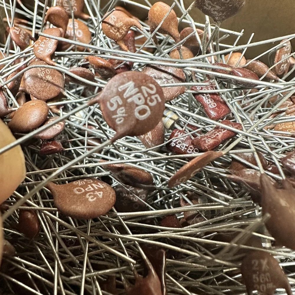
My first batch that I bought was a literal double handful of random NPO capacitors (and a few other ratings mixed in for fun) thrown into a box from eBay. I knew what I was getting so I also picked up some divider boxes to sort them when I got time. Now they are all sorted and I know where to find what when I need it. Of course, I don’t have every conceivable size to choose from but I do have a large assortment and can get by with most projects with what I have. Things like this are what I wished I had learned in trade school… I guess I should have chosen college instead…you know what they say about hindsight though...
The photo of the board above that shows all the leads connecting to temporary test points I soldered to the board has these capacitors on it. They are temporarily soldered on as I am experimenting with various values in different locations to see what will get me to where I need to go.
I tried to use the online calculators but this filter doesn’t fit into any of those models and all the outputs from those tools were not working for me. It looks like the coupling capacitors are also used to also limit the signal level from stage to stage as well. Correct me if I am wrong in this assumption, but tiny little 5 and 8 pF capacitors are not letting a lot of energy through them, even at HF frequencies and there are two in this filter circuit. I can only assume that they are also using these to match impedance as well or a larger value would couple the stages with more signal. Anyway, I was stumped and asking the internet for help is literally begging to be slandered and chastised for being stupid, so I didn’t even bother with that option. That only left experimentation and experimentation is what I did. I put all sorts of outlandish caps in this filter and found success doing it this way. It took me a few hours, not gonna lie, knowing how to calculate these sorts of things would have been immeasurably easier, but I was able to get the signal on the output trace of the band module and it had decent signal level too! Honestly, I am going to revisit the output signal level when I get back home (I may have already done it by the time this goes live on my site) and see if I can attenuate the level somewhat as it is higher than what the base of Q16 on the receiver control board shows in NA5N’s pictogram.
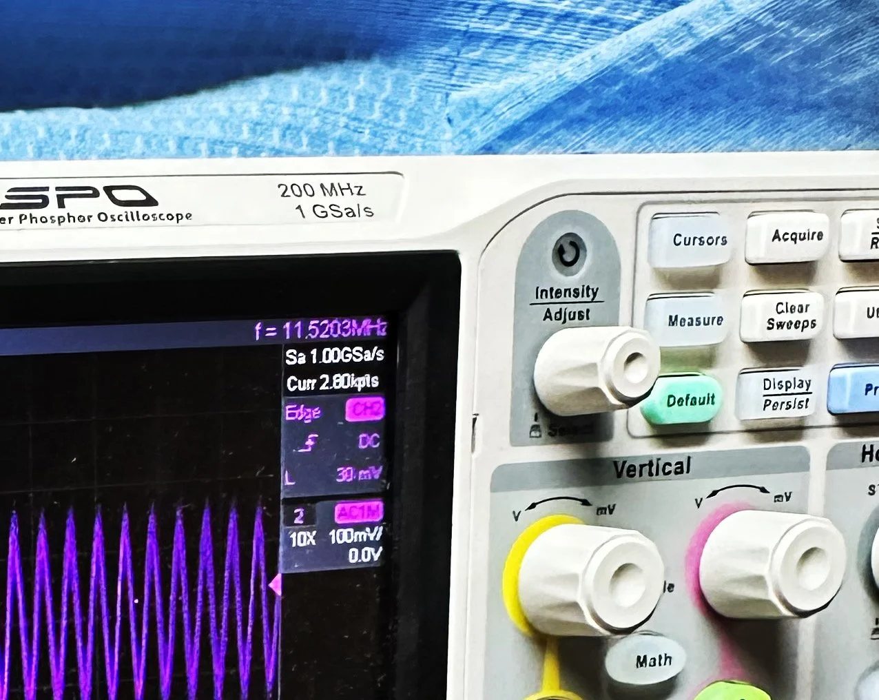
What you are seeing above is the output of one of my Argo 556 radios that I used as a test bed to check the signal levels and such to see what was going on with it. As you can see I simply connected to the output of the radio and looked at the signal going into a 50 ohm dummy load. I did the math (I know, I know… this has not been a great idea for me in this blog post… lol) and it comes out to about 1.8 watts and not 5 watts for this radio (I have not attempted to turn up the transmit power on this unit yet either so it might simply be turned down or something like that. Let me know if my math is wrong here, but 27 volts peak to peak and 50 ohms should give me a power level of 1.82 watts at the antenna connector?
Power= peak voltage (13.5volts) divided by the square root of 2 and then that is divided by resistance.
All that aside, I took the newly minted 60 meter band module up to the shack and setup a Scout 555 and connected it to my home antenna. Tuned the antenna up and started looking for a QSO. I promptly found one and had a short ragchew with VE3USP in Ontario despite some QSB along the way. It works perfectly too. I do have to dial up 600 hz to be on frequency as it is a Scout 555 after all, but that is not a problem!
So I am not completely finished with this module as of yet. I still want to look at that output filter from the mixer and tune it some more. It is close, but it is not right as the signal level is too high. I found I missed a couple of capacitors when I dismantled it to clean it that need to be NPO capacitors instead of what I currently have in place as well. I would also like to improve upon my terrible painting skills if I could figure out a way to do it…lol Seems acrylic craft paint might not be the best solution here…
Next week we get into what happened when I took it to a POTA park… hint: I brought it back home and got inside a little more to fine tune it…. I discuss this next week and show you what I came up with for the mixer output filter ultimately.
To read the other parts:
- Part 1: Initial Conversion and Filter Design
- Part 2: Crystal Selection and Mixer Circuits
You can help support this website by using these Amazon Affiliate Links:
QRP/Portable Radios:
Antennas & Tuning:
CW Equipment:
Power & Accessories:
Organization & Transport:
BONUS ITEMS
73
WK4DS - David
![Converting Ten-Tec Scout 555 to 60 Meters: Complete Band Module Modification Guide [Part 1]](https://images.squarespace-cdn.com/content/v1/5d17806ce65eba00011667cb/18e0d4d9-ed31-466a-884c-4a94776d9a58/IMG_1197.jpg)
Converting Ten-Tec Scout 555 to 60 Meters: Complete Band Module Modification Guide [Part 1]
You see it was starting to look pretty daunting since I didn’t understand what the reason for the odd frequency crystal was and that there were 4 tuned filters in each band module. Also the crystal value just didn’t make sense on the surface.
When I first decided I wanted to make a band module for the Ten Tec Scout 555 that was able to get on 60 meters, I had no idea what really was involved.
A little backstory here is kinda needed, you see the Ten Tec Scout 555 has become one of my favorite radios for POTA operations and I even find myself setting one up in the shack to tinker with from time to time. I own 3 Scouts and 2 Argos at the time of this writing if that tells you anything. I don’t know if it is the simple elegance of the radio or the fact that it can operate on almost all of the HF bands in such a small form factor, but I love it. Well there are a few things for sure that draw me to this radio like the fact that these radios have the now infamous Ten Tec full QSK (full break in) keying. This keying works flawlessly too by the way. Another reason for such love for these radios is the amazing receive they have even for such a compromise design. With headphones (or even those little earbuds), it is pretty easy to hear stations in the edge of the noise floor and make contact with them.
Well, if you noticed I said… almost… all the HF bands… This is because we have been granted, by the IARU, some space in the 60 meter band as secondary users.
Some of this band space is open to use with power levels up to 100 watts too. (There has been a recent change that modifies the allocation to allow a bandwidth section that is non-channelized but limits the power to 9.5 watts ERP so play in this area carefully. Basically this new region is a QRP only region for now.) Aside from that though, the Ten Tec Scout 555 can operate quite legally in the other 4 sections… or it could if… there was a 60 meter band module… You see this 60 meter band allocation happened after the Scout 555 production run had ended, so Ten Tec never made a factory band module for the 60 meter band that I am aware of.
I started this journey by digging through the owners manual for the Scout as Ten Tec always shipped complete schematic diagrams with their radios. Sometimes there would be missing insignificant data, but you could trouble shoot the radio just fine with them. Once the radio diagrams were located, I started looking at how the band modules made it change bands.This turned out to really be quite simple but I was missing one or two critical values. You see the Ten Tec Scout 555 band modules have a crystal in them and the frequency on the crystal didn’t make sense…at first.
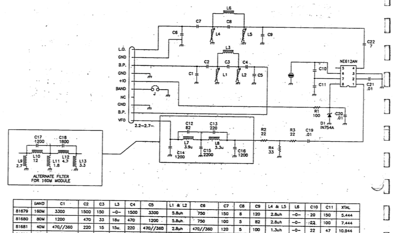
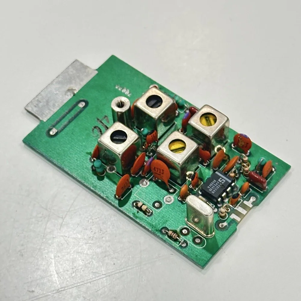
Above is the schematic and a photo of the board that goes with it showing the crystal that I couldn’t understand. This is what tells the radio what band it is on. Looks pretty straight forward at a glance, doesn’t it? Well look at that XTAL value at the end of the chart for 80 meters. Yeah, it takes a 7.444 mhz XTAL to get to the 80 meter band. So I figure the PTO is something like 3.0 mhz so it can get the first negative harmonic when mixed or something like that…nope…turns out I was totally wrong…
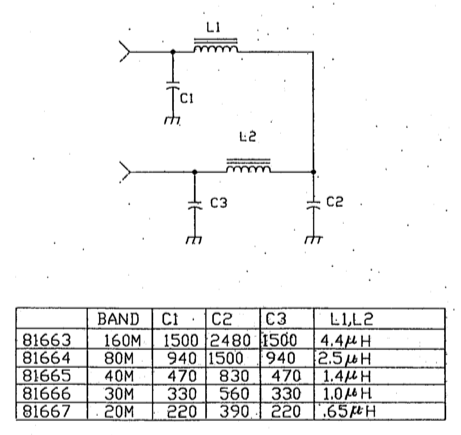
This is the other half of the band module. A classic low pass LC filter and that’s all. This is the output filter that the 50 power amp sends the RF to before it goes to the antenna. Below is what this part of the module looks like. These inductors and capacitors are shielded as they are delivering and filtering considerable power and could interfere with the small voltage levels on the other board that sits right beside it if they were not in the “can” or otherwise known as a ground shield. I don’t know why there is a hole in the shielding either as there is no adjustable parts inside the “can”. I chose this particular 80 meter band module for another reason as well. I have been inside this filter circuit before. When I acquired this module, the fellow I got it from told me it was dead and gave it to me. Turned out to be a broken lead on one of the inductors in this can. It took me a while to desolder this monstrosity to be able to access the parts inside of it. But persistence paid off as I was able to get it repaired and back in operation. I took a lead cut from a transistor and soldered it to the wire on the inductor and simply re-soldered it to the board and it came right back to life. So if you have a module that just stops transmitting all together, I recommend you pull the lid here and look at the inductors to see if one is broken free from the board, that might be all that is wrong with it. I also hot glued the toroids in place to help prevent this from happening again. Anyway, back to the project at hand…
I also looked inside several band modules to see what the differences were and I found some interesting things when I did. For starters, the 10 and 12 meter band modules both use the same circuit boards. They just leave out the second crystal and the switch parts for the second crystal and put a crystal in it for the 12 meter band only when configured for 12 meters. I guess, to be fair, I should have also figured out how the PTO worked as well then I could have figured out the reason for the odd crystal values, but here we are…
Another thing I found was that the engineers at Ten Tec used whatever circuit board blanks that they had on hand to build the band modules apparently. I say this because I found 10m circuit boards (the ones meant for two crystals and the switch) fleshed out with parts to make them into 40 m band modules. (Like the one in the photo above) They apparently just used whichever ones they had on hand at the time. Needless to say, what I thought was going to be simple was starting to turn into a pretty major endeavor.
You see it was starting to look pretty daunting since I didn’t understand what the reason for the odd frequency crystal was and that there were 4 tuned filters in each band module. Also the crystal value just didn’t make sense on the surface. The values were all over the place. I was about to throw in the towel calling it just too complicated, even though the parts count in a band module is really low…till I found two things. One was I looked up what the “555 timer” on the board actually was (Here is a hint, it aint no timer) and the other was NA5N’s website.
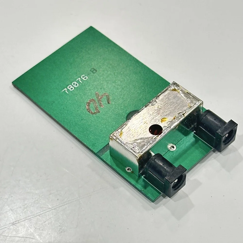
Excerpt from NA5N’s website showing the level of detail these drawings contain.
NA5N’s Scout 555 page is a figurative gold mine of information with just plain cash money piled on top of it, (just to drive this point home take a look at the piece above I grabbed for reference). I can not thank him enough for this information as without it I would not have been able to get this project working as quickly as I did. He also has some really interesting mods he has done to his own radio as well. If you want to perform his mods on your Scout, he gives you detailed information on what is done and literally how to do it…step by step almost. The greatest part of his page though is his info graphics he has built and placed there. These graphics show all sorts of information that the radio schematics leave out.
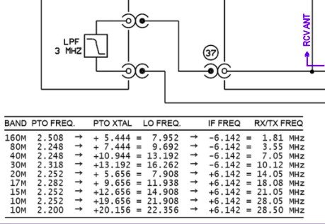
This and MUCH more is available on the NA5N website.
Things like the frequency path (pictured above) through the radio in a chart so you can understand how the engineers at Ten Tec arrived at each band frequency with these plug in modules and a PTO. Complete with oscilloscope test point and what you should be seeing at these points! Like I said, a gold mine buried in cash money…
Based on his chart I went through the band module and looked at the filters for the various circuits and decided (more like assumed based on the values of the parts) that I could simply re-tune an 80 meter module and “push” it up to 5.3305 mhz easily enough and without too much fuss…nothing could have been further from the truth.
So I start tinkering with the filters and piping them through the nanoVNA into the s21 input so I can see the filter shape and all is well from what I can see. Turns out the low pass 80 meter band module filter cut off frequency was about 5.5 mhz or so to start the rolloff so the 60 meter band was still in the pass band! One down three to go! Next I figured out that the PTO is the same for every module since it is part of the radio and not in any of the modules so that filter also didn’t need any mods. This left two filters to re-tune, just so happens it is the two with the adjustable inductors in them. So I start with the LO BPF (Local Oscillator Band Pass Filter) that filters the signal passing through the radio from the antenna. Why they call it the same thing as the LO BPF that is in the output of the mixer chip is beyond me, but here we are… This didn’t go well as I was not able to get enough adjustment out of the inductor slugs to get the passband up to 5.350 mhz, shoot I couldn’t get it to tune up past 4.5mhz if memory serves me. It was far enough that I couldn’t get it work so I looked at what I had and decided to wind some air-core inductors to a lower value and see what I could do like that.
Well, to be honest, I don’t know how I was so successful here. Maybe it was the sheer audacity in the fact that I was woefully unskilled in building filters for HF or the mind boggling lack of knowledge of how filters work and how to make them, but I got it almost perfect on the first try! I made a couple different inductors by winding magnet wire on a 1/4-28 bolt (that’s a little over a 6mm bolt for the rest of the world) and the threads made getting good tight coil layers easy. I borrowed my friend’s LCR meter and measured them and blissfully declared them good to go at 2.0uH each. Did I mention this is a budget LCR meter and I have no way of knowing what the level of calibration is for this part of the meter? I also learned later that I can measure my inductors with a signal generator and a oscilloscope. Guess who now owns a signal generator as well as an oscilloscope...
Once wound and “measured” in the board they went! I then tinkered with the capacitors till the pass-band looked close to what I thought it should look like. (I had also learned from the wonderful world of youtube that I should see less than 1dB of loss in the pass-band and the 3dB cutoff point is where the filter technically is measured..typically.) As I mention in a bit, I used the wrong kind of capacitors (the little blue ones) to start with, although the module did work like this, I updated it with NPO capacitors ultimately as well.
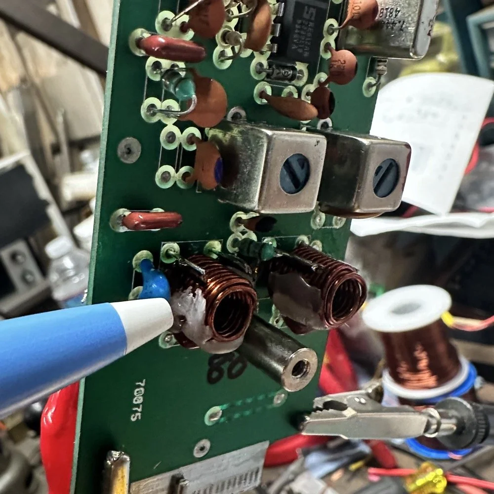
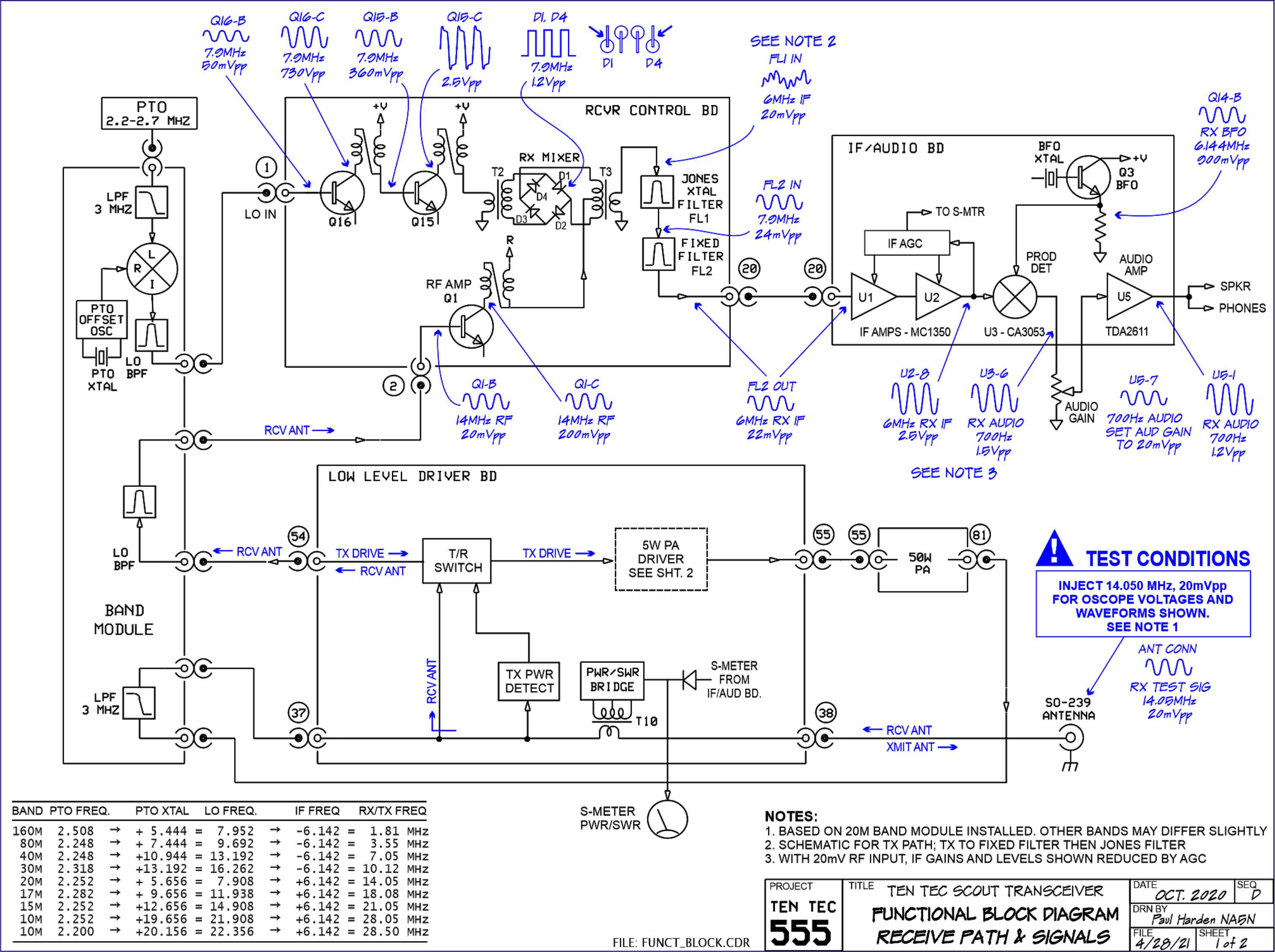
I went down a long path of learning on this project, if you haven’t already noticed from the inserted comments in the story. I have very little formal training in Electrical Engineering, you see I went to a two year trade school back in the 1980s and basically got the “intro to electronics” that EE’s would get before learning things like matching the impedance of the filter to the next stage and to use temperature stabilized capacitors in RF filters so they don’t move the pass-band around when they get warm. NPO capacitors have become my best friends here…lol. A hint for my peeps who also didn’t study RF in college, look at the circuit board above that has the crystal on it. You will see the little capacitors on that board and some have little painted tops on them. This indicates NPO capacitors when the letter designation will not fit. I have now purchased a lifetime supply of these caps off of eBay…haha.
Anyway, now the pre-amp band-pass filter was functioning like it should. One to go…
Tune in for part two where we get into the problems I had to solve to get this module working and how well it works now that I have figured out my mistakes.
Continue reading the series:
- Part 1: Initial Conversion and Filter Design
- Part 2: Crystal Selection and Mixer Circuits
You can help support this website by using these Amazon Affiliate Links:
QRP/Portable Radios:
Antennas & Tuning:
CW Equipment:
Power & Accessories:
Organization & Transport:
BONUS ITEMS
73
WK4DS - David