WK4DS Amateur Radio Blog
Back on the Air for a POTA Activation
Today saw me back at US-2169 for the first time in a while…
Today saw my take the old Dodge over to my local park (US-2169) for a short activation. I have been busy in the machineshop these last few weeks so there has not been much time for POTA. I have actually not been to a park in several weeks and was starting to miss it.
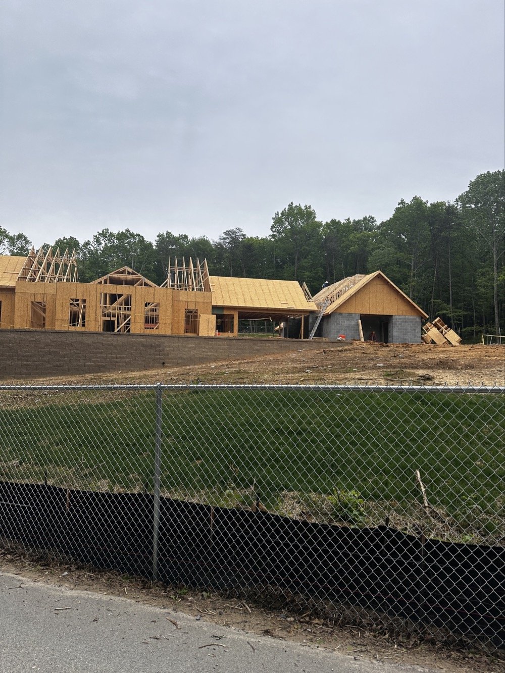
Update on the park visitor center upgrade in progress. The grade work is done and they are framing the new building at this point. It is coming along nicely too.
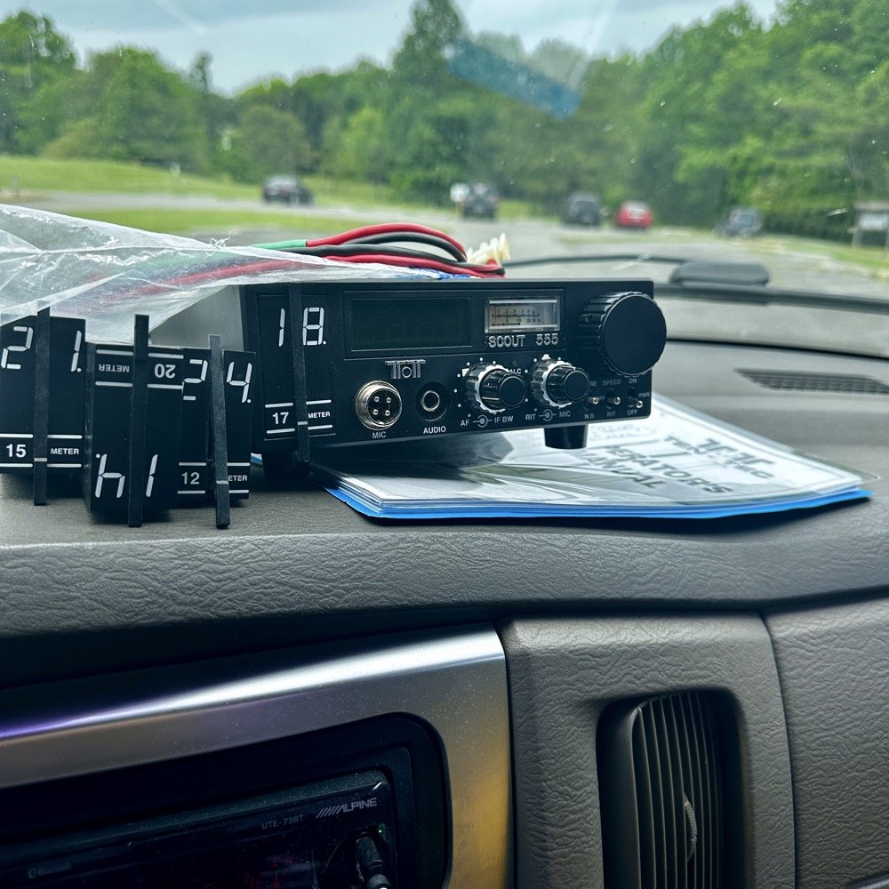
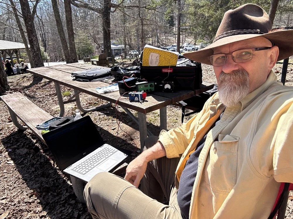
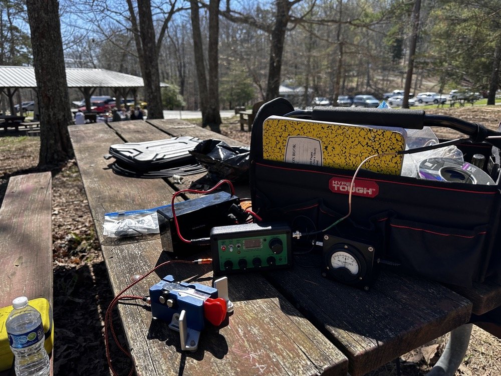
Setup of my POTA rig for HF operation
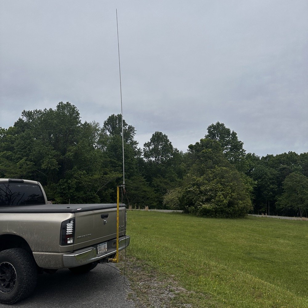
I went up to the frisbee golf course again as this is a great place to setup for POTA. A lot of people will use the nearby pavilion when they setup, but my antenna mount, being attached to the truck, makes it alot easier to operate from the truck. This is an amazon 18’4” whip that I bought, you can get one too at this link: Link to 18’4” whip on amazon Now, to just let you know, this is an affiliate link, but it doesn’t change the price from what I can tell… At the time of this writing, they were on sale for 27$, which is incredible!
Today I used the 18’ 4” foot vertical telescoping antenna and two radials attached to the base. Then ran a coax into the cab of the truck to the front seat where I normally set up the radio in the front passenger seat. Something I noticed today was that no matter what band I was on, the SWR plot would never get better than 1.5:1 (which is perfectly fine BTW) but I can normally get way better matches with different radials, which tells me that the radial length is more important that people let on…
Next, I chose the TenTec Scout 555 as it is a wonderful CW machine. It does have a little bit of drift in the VFO, while it warms up, but it is not enough for me to worry about. I started on 20 m in the CW portion of the band and hunted stations to start with. I worked another POTA site for a park to park contact before finding my own space and setting up there. I made 19 CW contacts on 20 m before I decided to move to 15 m to see what I could find there next.
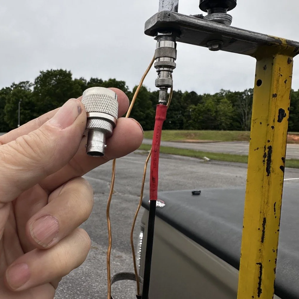
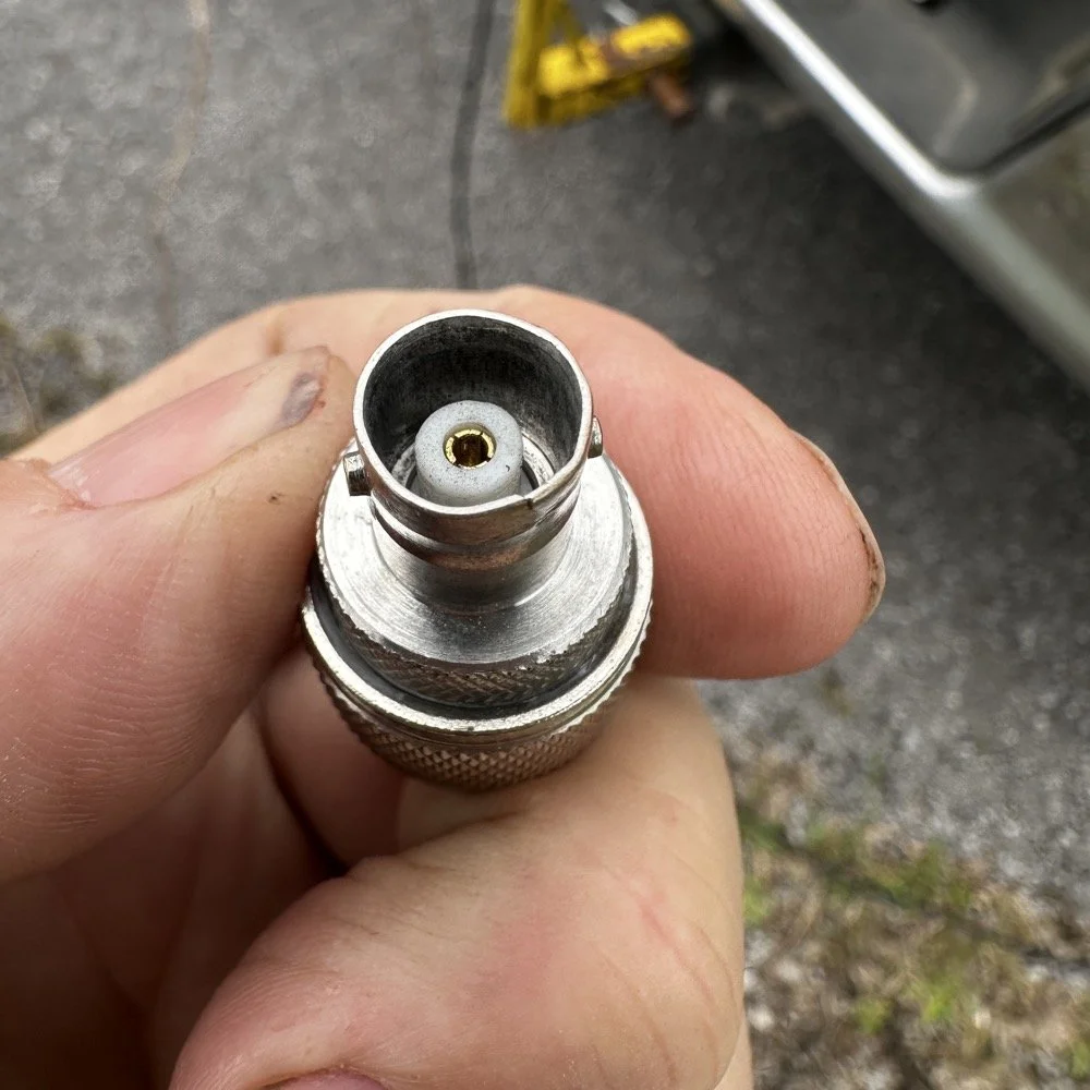
Pay attention to bad antenna connectors…
When connecting the antenna today, I had trouble getting the BNC to attach, upon closer inspection I had found that it was crushed from impacting something in the truck… Probably when it was in the red Chevy as there is less protection in the back of that truck as compared to how I store it in the Dodge. Oh, and yes, my heat shrink tubing on the coax has slipped back for some reason. I noticed it when I was breaking down and simply slid it back into place…haha. I did not notice this until I attempted to use it today to operate this activation.
I attempted to straighten the damaged BNC connector with my Leatherman as best as I could, but it didn’t work really all that well so I got in my adapters for my nano VNA and robbed the one that was in that pack and used it instead.
This is a great example of why you always carry spare parts for all of your connections so that you don’t get shut down because of something getting broken unintentionally that you are not aware of.
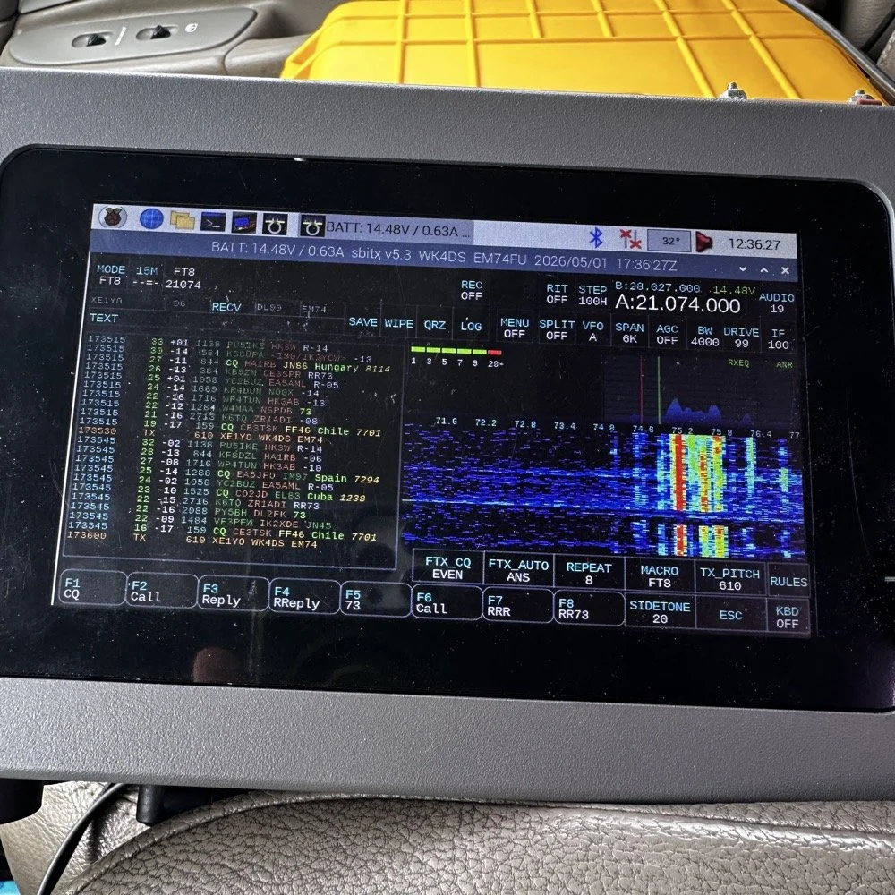
The HF Signals sBitx V3 and native internal FT8
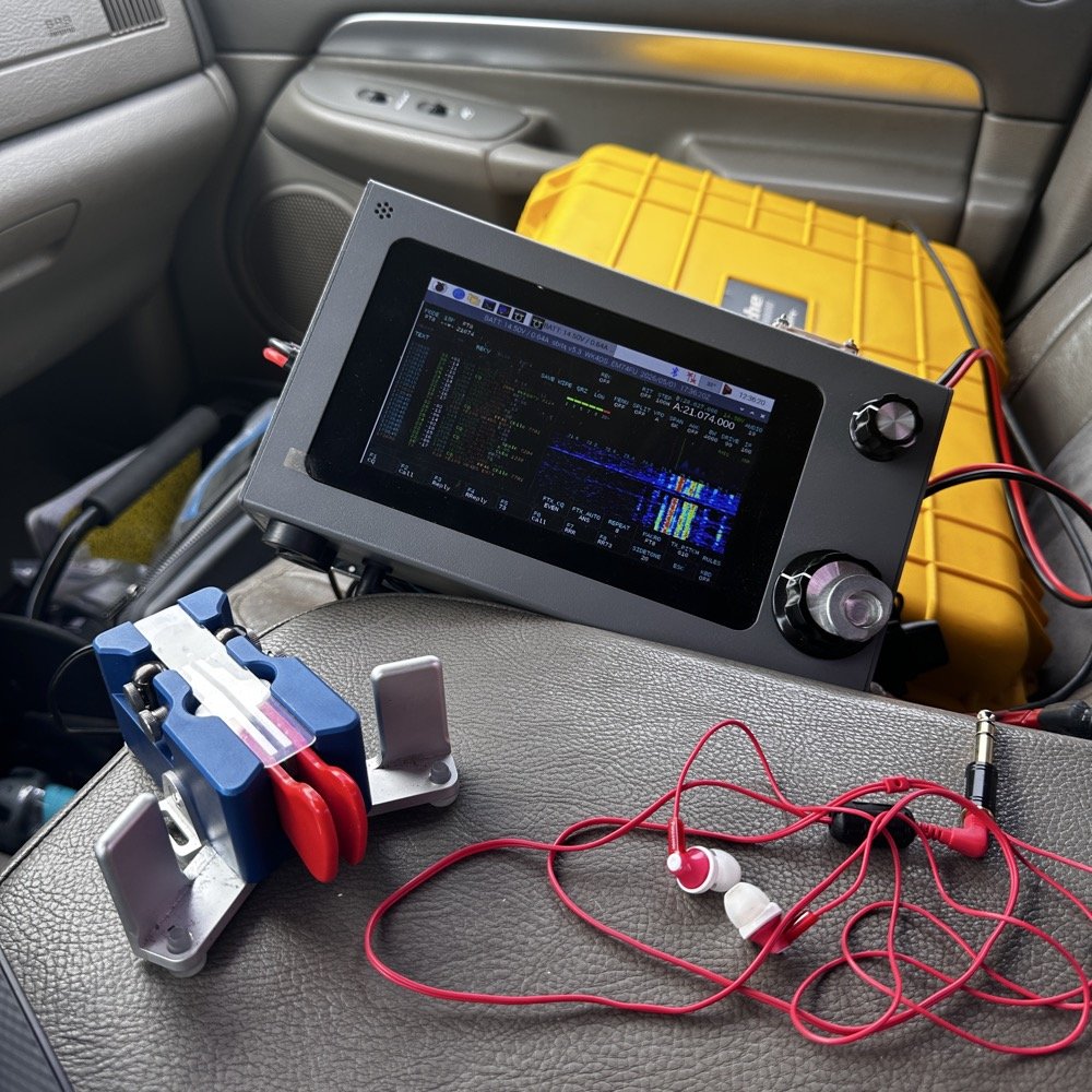
Once I finished working CW on the Scout 555, I decided to get the sBitx out for a while to work some FT8. I really love using this radio for FT8 and CW in parks, it works so well and with the version 5.3 software, it has a metric ton of great features. The waterfall works well and the automatic modes in FT8 are really handy too. This radio is 25 watts on the lower bands and trails off to about 12 watts on 10 meters. This is plenty for me as I work a lot of QRP anyway so little to no power output is fine for the most part. Would it be nice to work with more, yes, but I can manage without it just fine.
Today I only used it for FT8, but I also will use it for CW from time to time. It is a little temperamental in CW since it is a Raspberry Pi 4 running in the background, but once you learn the keying, it works fine up to about 23WPM for me without too much issue. Using something like the Begali Traveler CW Key in the photo below also makes it more fun too. A really nice key is always a good thing to have with you.
Once I worked a few FT8 contacts on 15 meters, I dropped down to 17 meters and worked a few more there before shutting down for the day and heading home.
I noticed when I was getting ready to leave that the truck motor was “squeaking” when it was idling and when I investigated further, I found that it was a pulley on my fan belt had a bad bearing in it. So I went to the auto-part store and got a new one to replace it with. Once home I was able to replace it in short order so that I would be ready for the next POTA outing that I wanted to go on. Sometimes things just come up and you have to take action…haha.
Thank you for following along and I look forward to sharing something with you again soon, till then 73!
You can help support this website by using these Amazon Affiliate Links:
QRP/Portable Radios:
Antennas & Tuning:
CW Equipment:
Power & Accessories:
Organization & Transport:
BONUS ITEMS
My first POTA 2fer, with a QRP radio, and a Solar Storm!
Today I activated US-0716 (Chickamauga Battlefield) for my first-ever POTA 2fer! Between solar storms, parking challenges, battery failures, and meeting Dan (K2DTS), this activation had it all. Here's what happened when Murphy's Law met a QRP radio during less than ideal conditions!
Today saw the old red Chevrolet transporting my POTA gear over to Chickamauga Battlefield National Military Park which is park number US-0716. I have activated this park many times in the past, but unbeknownst to me was that the location I usually used to activate this park also allows for the activation of the Trail of Tears National Trail as well as it follows old HWY 27 right through the park! I have been activating a 2fer for years now and had no idea…live and learn.
This “parking lot” has only 2 spaces in it, but it is close enough in proximity to the main road to allow for a 2fer when activating POTA
I arrived on station to find that only one spot was available and no one around the truck. This matters as Dan (K2DTS) had mentioned dropping by to see the CW setup and to observe a CW activation for a little while. Turns out the car in the other space was not him. He would arrive later, which was a much needed “shot in the arm” to lift my spirits. You see, today was one of those days when the sun was really angry while I was setup to activate. The solar K index was either 5 or 6 which isn’t good…especially for QRP… My QSO count today was not all that high, but I still had a relaxing and fun time at the park none the less.
This location works well with my truck mounted antenna setup that I built. I used my old reliable hamstick collection today to get on the air and true to form, they worked pretty well. I have also refined my tuning system as well. I will give you the quick rundown on how I do it now. This works especially well with hamsticks as you will soon see.
Hamsticks are a very viable antenna system for POTA activators. They are easy to setup and work reasonably well for their tiny size. They usually have good power handling so digital modes like FT8 and even good ole CW are not a problem for them. Of course SSB is always fine if they can handle CW…
My Hamstick Antenna System and Color Coding Setup
Above is my modest hamstick collection to date. This is the 5 bands I use the most and I wished I also had the 10 meter version as well…but I digress. It is a good idea to do something to tell them apart. The labels are not very durable from what i have seen and so I chose to color code mine with various colors of electrical tape instead. Red - 40meters; Blue - 30 meters; Yellow - 20 meters; Brown - 17 meters; and Green - 15 meters. These are what I have been using for a long time now and they work well. These are made by three different companies too so the brand doesn’t really seem to matter. I have also converted mine over to the QD attachment design so that I can change bands fairly fast…well it is faster than threading them into the socket…haha. I have owned and used this exact setup for quite some time now as you can see from this blog post I wrote a good while back.
I also store them inside a PVC pipe I made into a storage tube. It is almost 8’ long so I can keep the “stingers” on all the base load coils which prevents me from mixing the wrong tip with the wrong load coil. I built this tube steel mount to fit inside the 2” receiver on a pick up truck, this allows for it to do two things at once. 1) It allows the antenna to be setup quickly and easily on any vehicle with a standard receiver mount. 2) I also built it so that it makes the base of the antenna at around 6’ above the ground. Getting the antenna higher does help with take off angle so I made the decision to make it taller than most. This also made it possible to string some radials at various angles so I can play with the impedance by adjusting the radials. If you look close in the lower photo, you can just see the radials connected to the base of the mount and running down out of the frame. These were tuned for 17 meters like this and they worked incredibly well in this configuration. When you only have a few watts like with the Penntek TR-35, you need all the help you can get…haha.
17 meter hamstick deployed during a POTA activation for CW and FT8 use. You can also see the highway in the background that is designated the Trail of Tears trail as well.
I setup in the passenger seat again, but to be honest, this was not ideal. I struggled to get all the stuff connected and stationary today. I also had a problem with the battery in the little power pack I had built…it was completely dead for some reason. I had used it recently but I didn’t think I had tanked it, anyway, not to be dissuaded I decided to get out the 8Ah battery and find a spot for it as well so I could power the station. You see, I needed the “power pack” so I would have a speaker. I figured that since Dan was going to drop by and hand out some, that I would make it to where he could hear the CW as well. This setup finally settled in and I was able to get on the air. This is when I figured out that the sun was angry…
I looked on the POTA spot page to look for a clear spot and there was only one other ham on the spot page, on 20 meters, in the middle of the day… Do you understand what this means? 20 meters is literally the honey pot of the HF bands when it comes to POTA. There is literally 2 dozen CW ops at times on this band and then there will be 2 on 17 meters. It will be that drastic and today there was me and one other guy in the Carolinas and that was it. Optimistic that I could at least get my ten in short order, I fired up the radio, dialed through the literal ghost town that was 20 meters and settled on a frequency around 14.063mhz and started calling CQ. It took about an hour to get my ten plus a few more, but I finally got them. In an attempt to get some stations I could hear in the noise, I even switch to headphones as you can hear MUCH weaker signals if you goto headphones over the external speaker that I am using. This trick didn’t work either as it turns out, that there has to be stations on the air for you to actually hear them… I had seemingly forgotten this minor detail on this day…lol.
POTA CW station ready for use, including the Penntek TR-35, home brew S meter and battery pack/ speaker combo unit. Also the Gemini travel CW key and the Dell Inspiron computer with HAMRS for logging.
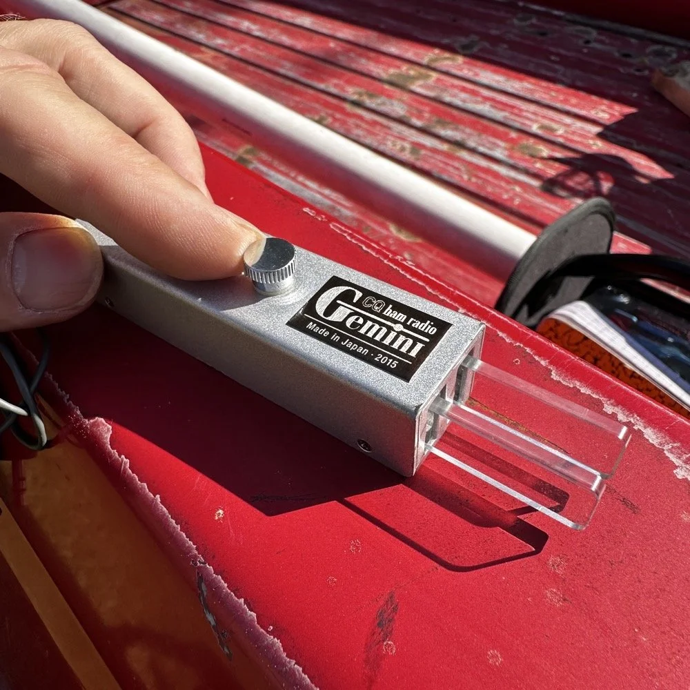
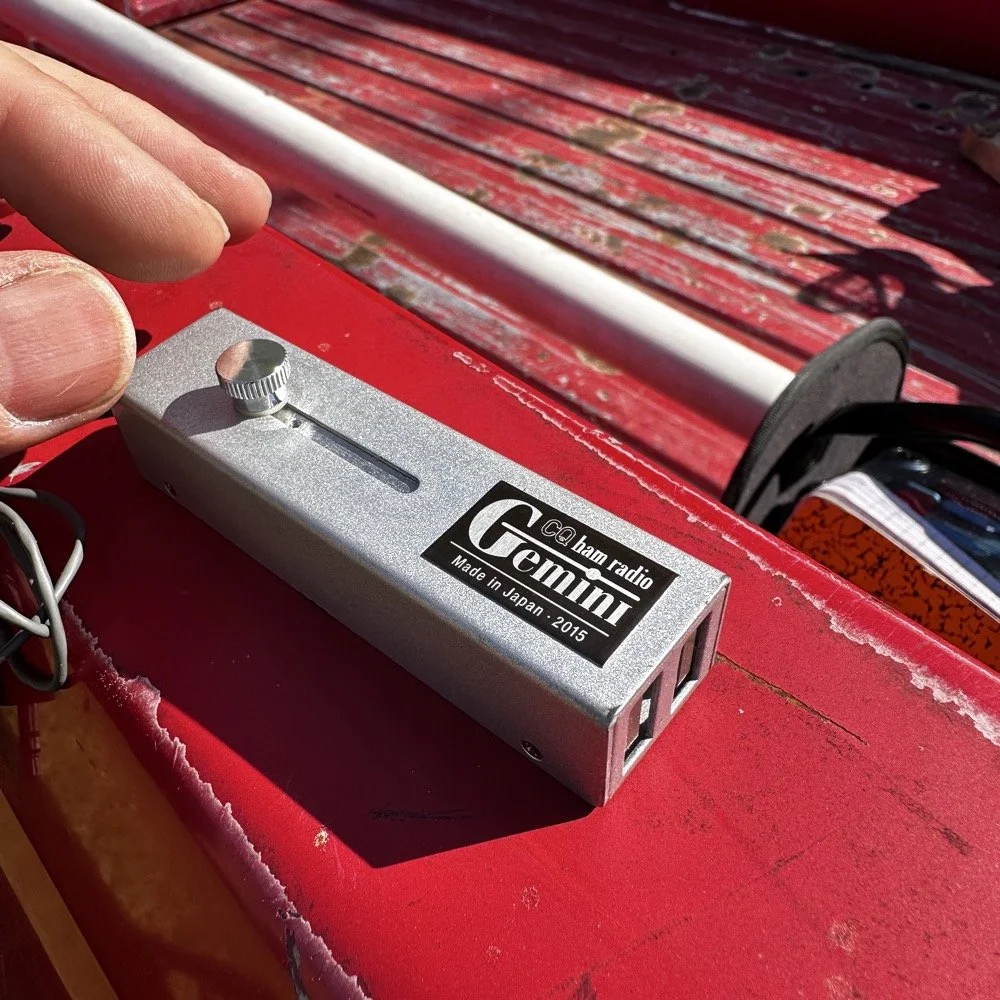
CQ Ham Radio - Gemini travel CW key is really well designed and cost effective. This is one of my favorite CW keys when I dont have a surface to set the Begali Traveler on.
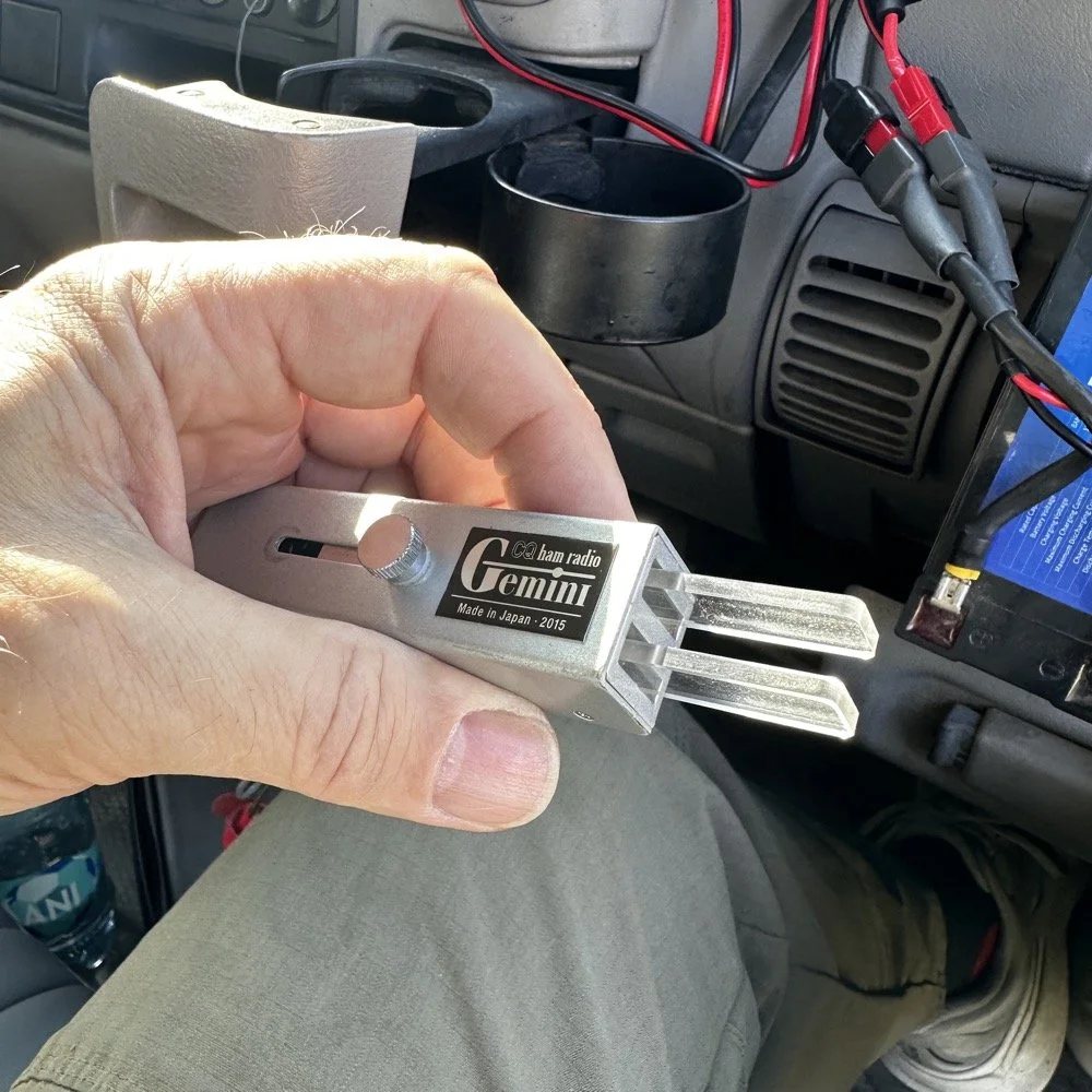
The Gemini CW Key: A Collapsible Treasure from eBay
Let me introduce you to one of my favorite travel CW keys that I use for POTA operations. This is a key I bought off of eBay initially and as of this writing, it seems to be the only place to get one of these keys now. Maybe an opportunity for a creative solution here… lol. Anyway, these are darling little keys that work beautifully and I always enjoy getting this one out. As you can see below, the reason I like this key is how it stows the handles when not used. You simply loosen the screw on top a little, slide the screw to the rear and this collapses the paddles inside the housing which protects the from damage when stored in less than ideal conditions. This key also is dead simple, lacking any sort of adjustments at all, you just plug it into the radio and use it. I like that to be honest…
GHD CW Key for portable CW operations like POTA.
Operating QRP During a Solar Storm (And Why 20 Meters Was a Ghost Town!)
So after I struggled around for a little over an hour to put 15 calls in the log…well…14 since one was a dupe… (duplicate calls on the same band, park, day and mode dont count to your POTA score)…I decided to put up the headphones and get out the HF Signals sBitx and work some FT-8 on 17 meters. I had not seen Dan so I figured the honey-do list got him or something and put away the CW gear while FT-8 hummed along in the background.
A lot of times, I will run FT-8 while I do house keeping chores like putting up radio gear from a different mode that I had just finished using or talking to the wife on the phone about what she wants me to do next after I finish playing radio… you get the idea. I can do some other things while keeping an eye on the display and letting it run in auto mode for a while. Well, not today buckaroo, seems the band were so bad that I couldn’t get auto to work today very well. I called CQ for a while to no avail. I finally started hunting other stations can answering their CQ instead. Switching to this tactic netted me 5 more contacts before I closed out the log for the day. 18 valid QSOs will do just fine…actually, 36 since I activated the 2fer today!
If you will notice the waterfall in the photo below, you will see that there really were not that many stations on the FT-8 segment…which is usually choked pretty tight with stations. The bands were just that bad. Even with these terrible conditions, I was still able to get 5 calls in the log for today on FT-8!
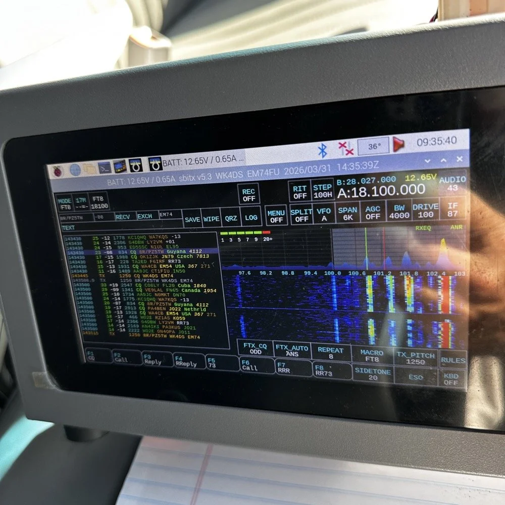
sBitx by HF Signals is a SDR powered by a Raspberry Pi 4 or Pi 5 SBC and does all sorts of things a regular radio can not do.
Meeting Dan (K2DTS) and the Ham Radio Community
While I was taking some of these photos and cleaning up the unneeded ham gear after switching to FT-8, look who stopped by to say hi and see the station! Dan (K2DTS)! He missed my CW portion of the activation and instead of setting it all back up, I did show -n- tell with him about all the gear I had brought to the activation. You have to understand that this is fairly substantial…haha. We talked for probably 20 minutes or maybe even a little longer about all sorts of things and had a great eye-ball QSO. I hope we can link up again at some point so I can get him on the air with CW so he can make some contacts too.
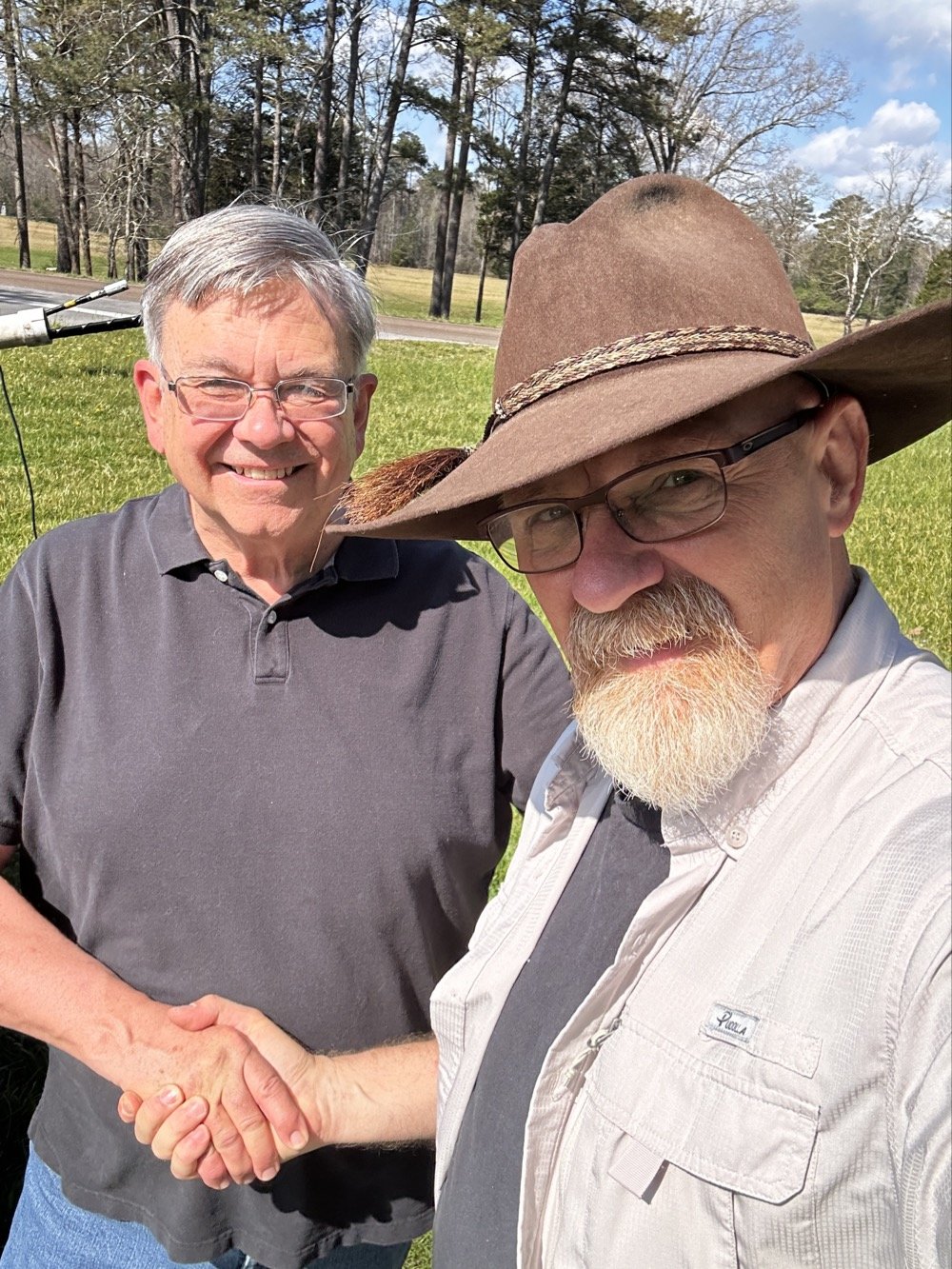
Ham radio is a wonderful community that has a large number of great people like Dan (K2DTS) who came out to the activation site today to see the setup.
Some days you don’t have to make a ton of contacts (although this never hurts…haha) to have a good time. Any day at a park with a radio is better than your best day at work. Knowing this I will always choose POTA over going to work… lol. Thanks for coming along today and I hope to work you on the air soon!
72
David - WK4DS
You can help support this website by using these Amazon Affiliate Links:
QRP/Portable Radios:
Antennas & Tuning:
CW Equipment:
Power & Accessories:
Organization & Transport:
BONUS ITEMS
Over 80 POTA QSOs in “less than ideal” conditions…
I activated US-2169 (Cloudland Canyon State Park) and made over 80 CW contacts despite lawnmowers, kids, and Murphy's Law doing its best to sabotage the activation. Here's what happened when "less than ideal" conditions tried to stop me!
Let’s talk about something that not a lot of people consider…what do you do when you get to a park and things are not like you imagined? Do you turn around and leave? Do you complain to park management? Do you setup and “get your ten” as fast as possible? What? Leave it in the comments what you do when you have problems like I did today?
POTA Park Conditions
Here is the setup, today I went to US-2169 (Cloudland Canyon State Park) to get on the air with my little Penntek TR-35 QRP radio and found some interesting things happening at the park today. As you can see below the weather was basically perfect for a POTA activation today. It is still early spring here so the top of the mountain is still not showing much signs, but the valley is getting ready…so to speak. Some trees are turning green and some of the dogwood trees are starting to bloom so we are getting started. The temperature was nice in the mid 60s today and it was sunny so it was really nice. I Did find the direct sun to be annoying to be honest as it kept causing a lot of glare on my computer which made it hard to see at times, but I powered through this first obstacle…
My POTA station for today consisting of the Penntek TR-35, the Begali Traveler CW Key and my Dell Inspiron computer for logging.
The next thing I ran into was the kids, there were so many kids in the park today, it must be some spring break or something as there were a lot of groups of children like you see in the photo above (in the background) and they were…well…being kids… This in itself isn’t a problem, but I failed to bring any sort of flagging tape to mark my coax with so I was constantly looking over my right shoulder to make sure no one was about to walk into it. Actually, I only had to do this for a little while as there was something else that happened a little later that basically ran the kids off for me… haha. The lawnmowers…
The POTA HF Radio System Setup - Reliance Antenna
Anyway, let’s look at the antenna setup today to see what made it work so well. I started with two throw lines today so I could elevate the whole antenna off the ground. You see, I was using the Reliance Antenna Bugout 40m EFHW again today and wanted to replicate what I had back in Florida.
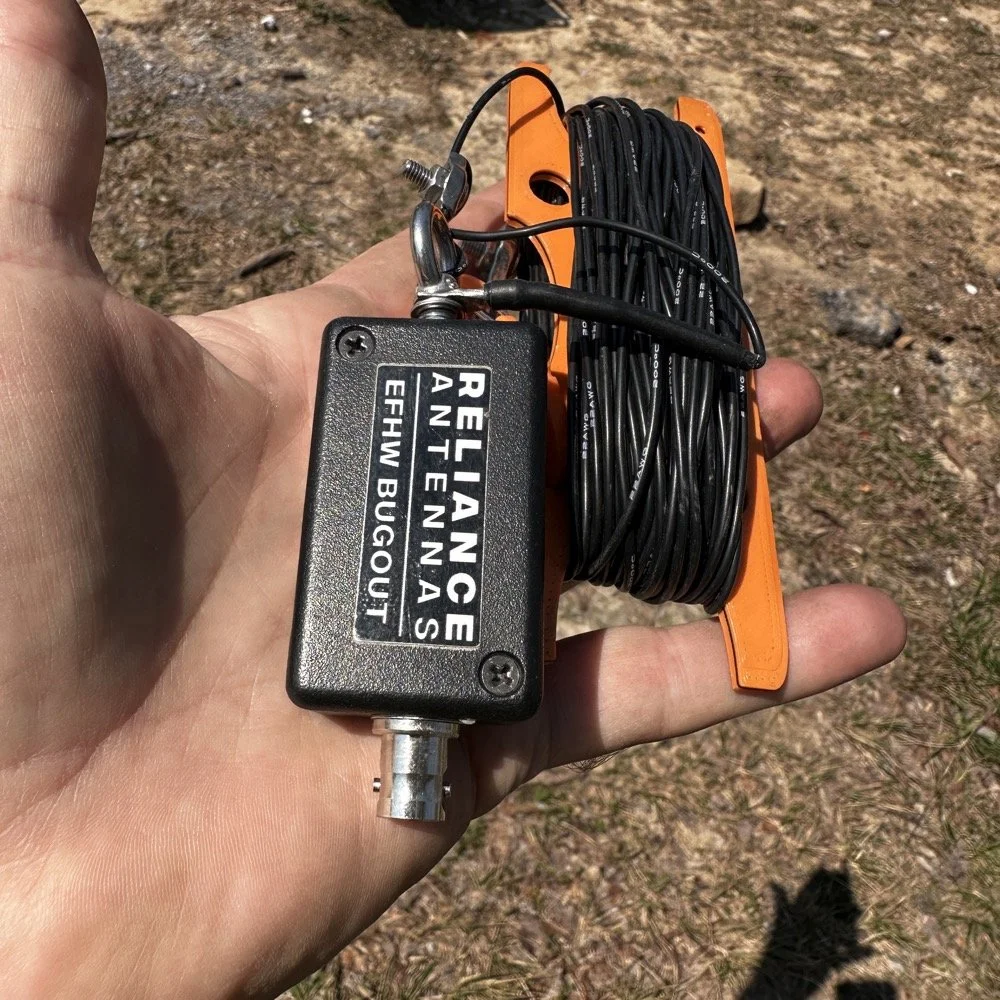
Today saw me use the Reliance Antenna Bugout 40m EFHW antenna to great effect even with all the problems.
I threw a line about 15 feet up over a large limb on the nearby tree to create the first point and this is where the coax went up to the transformer. I didn’t use a tuner today so I stayed on 20 meters the entire time today.
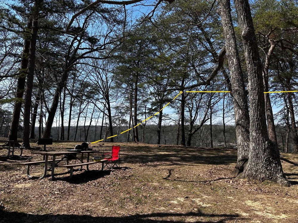
POTA antenna installation showing the 1st elevated point of the antenna transformer from the operating position.
I ended up tying the antenna lift rope (it is actually a small cord but you get the point) to the grill right behind the table to the left in the above photo. I used a Velcro tie to attach the end of the coax to the “possibles” bag on the table as it is heavy and the coax is really light and I figured it would hold it just fine…which it did. Next came the haul line to lift the antenna into the distal tree with the high end about 30 feet up. I use a stainless steel throw weight that I made in the machine shop so I can send this thing into the stratosphere if I want…haha. The wide angle photo below shows where the antenna was in the trees. You can also see another family at the picnic table in the background… more kids… haha. The good thing about using two haul lines in that the entirety of the antenna is WAY above where anyone could even get close to it. I was also using QRP power so there was no danger of RF issues here. The height is also beneficial for propagation and we will see a little later that it did in fact help.
Now, this antenna doesn’t have a counter poise of any kind so it uses the coax shield for the counter poise. To keep the stray RF out of the radio, I use a special coax from ABR Industries that has a ferrite common mode choke in one end. I simply put this end on the radio side and this allows the antenna to access the coax shield for counter poise use and also it keeps the common mode currents out of the radio… At least that is what I hope is happening, the strategy seems to work so I am running with it.
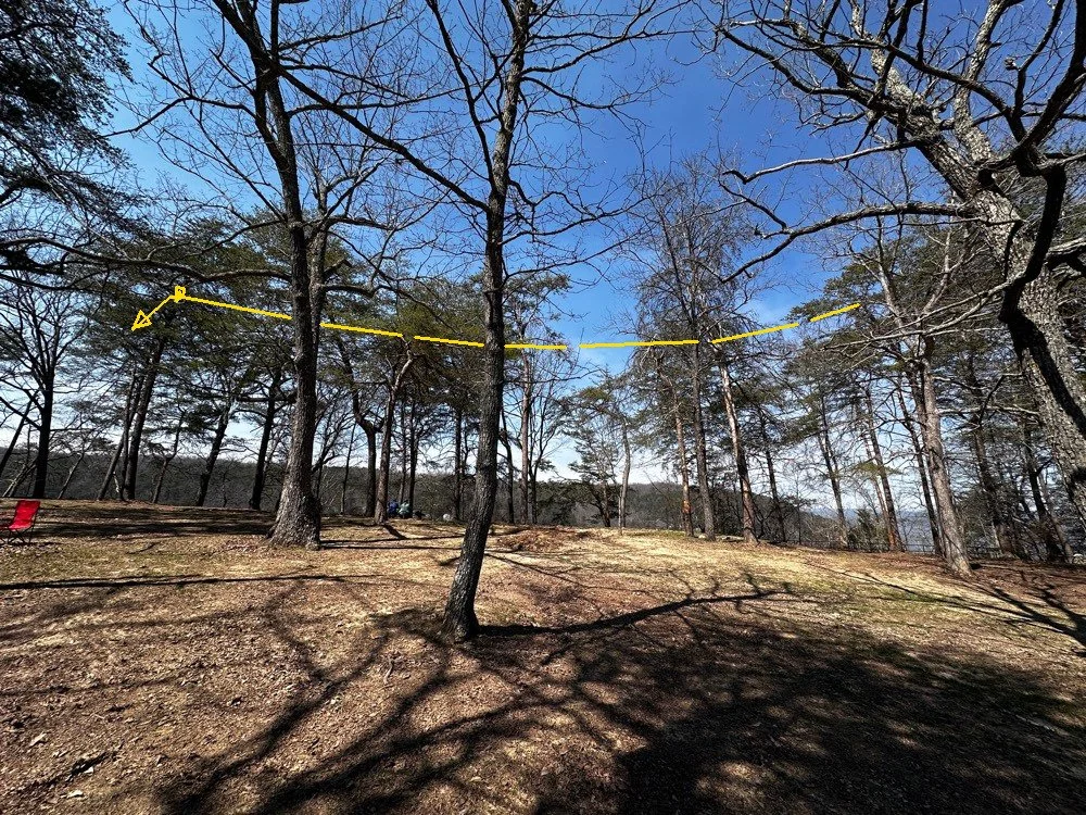
Position of the 40m EFHW antenna today for my POTA activation. Well above the ground!
POTA Activation Highlights
So once the radio was all put together and powered up on the table, I connected the speakers from my custom built project. This is a power pack with a 3aH Bioenno battery in a project box with a power-pole receptacle and a set of speakers so the Penntek TR-35 can be used like a regular radio since it has no internal speaker. I like running it like this if the ambient noise level is low enough as it allows the people around me to hear the CW as well. This sometime sparks interest and people will come over and ask me about what I am doing. A perfect5 opportunity to share with someone about amateur radio.
I started listening around a little and found 14.061mhz was clear after listening for a while. I have found that I will hunt me a clear frequency then get out the logging computer, boot it up and get the software running and ready to use, then I will spot myself on the POTA app all prior to sending that first CQ call. If you do any of this after sending that first call, you had better finish before the radio memory buffer does… that is all I have to say about that…lol. Just like clock work, I got an answer on the very first call too! I worked about 15 or 20 stations in pretty short order and then the QRM started. Someone decided that a QRP operator in the QRP portion of 20 meters activating a POTA park with a valid callsign was completely unacceptable for some reason. At first (read that as “for the first 5 full minutes” I actually thought they were just either missing me and sending their call twice or couldn’t hear me or something. You see, I was working stations the whole time! haha. So I finally stopped and listened and this person was sending real CW so it was someone who went to the trouble to actually learn it. But here is what they were doing, they would send a random letter, wait 3 to 4 seconds and send another random letter and then wait some more then do it again. All it really did to my normal QSO pattern was have me simply send everything twice as the spacing they were using allowed for this perfectly. Then I would send a CQ out of my keyer memory as the Penntek TR-35 has 2 keyer memories built into it. As soon as the CQ would start I could hear them in between my characters trying to jam me, so I would simply hit the keyer a second time and let it send the WHOLE message again and by then they either realized I was using a memory keyer or got tired of competing with a machine and would stop…till I would send a signal report. LOL. Remember what I just said about the cadence and my tactic to combat it? Well, I think they finally gave up at around QSO number 50 or so.
POTA station consisting of the Penntek TR-35, homebrew “S” meter, homebrew powerpack with speaker, Begali Traveler CW key and Relianca Antenna wtih ABR Industries Coax
Murphy’s Law at Work during a POTA Activation
That’s right, I made about 30 contacts while the QRMing op was actively trying to sabotage my activation. lol. So while this was going on, there was another “storm” brewing in the background… the lawnmowers had arrived…
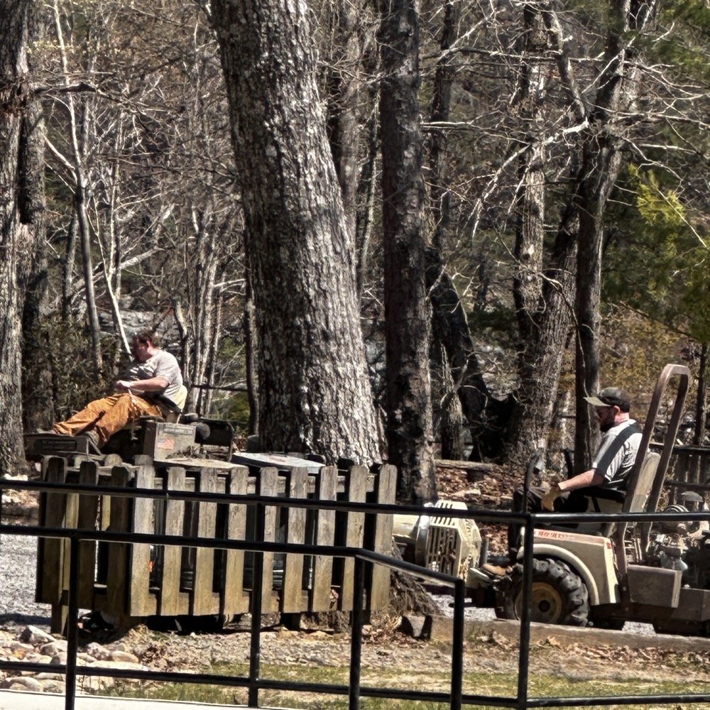
State park grounds keepers doing lawn maintenance.
They had been in the distance, but at this point they were starting to get closer and closer… At this point I am starting to think that these guys have been hired by the guy messing with me on the air! It was like they had been signaled or something. Just about the time the QRM vanishes, they show up!ll, to start with they were mowing over on the far side of the area so it was mildly annoying but not a real problem for my operating…but then…
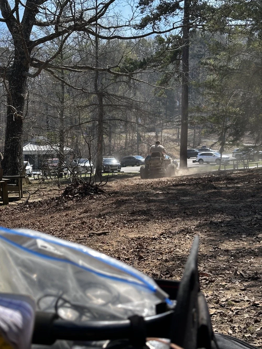
State park employee doing lawn maintenance while I activate POTA at US-2169 Cloudland Canyon State Park.
You guessed it, they felt it imperative to cut the dead leaves in the picnic area RIGHT BESIDE ME!!! Do you see any grass in that site?? I sure didn’t, but he sure was mowing it! Good grief, this is starting to get out of hand at this point and the sound of the engines was so loud that I had to resort to ear bud headphones to be able to hear. This did mitigate almost all of the noise from the mowers but it didn’t do anything for the dust cloud they were stirring up. Good grief.
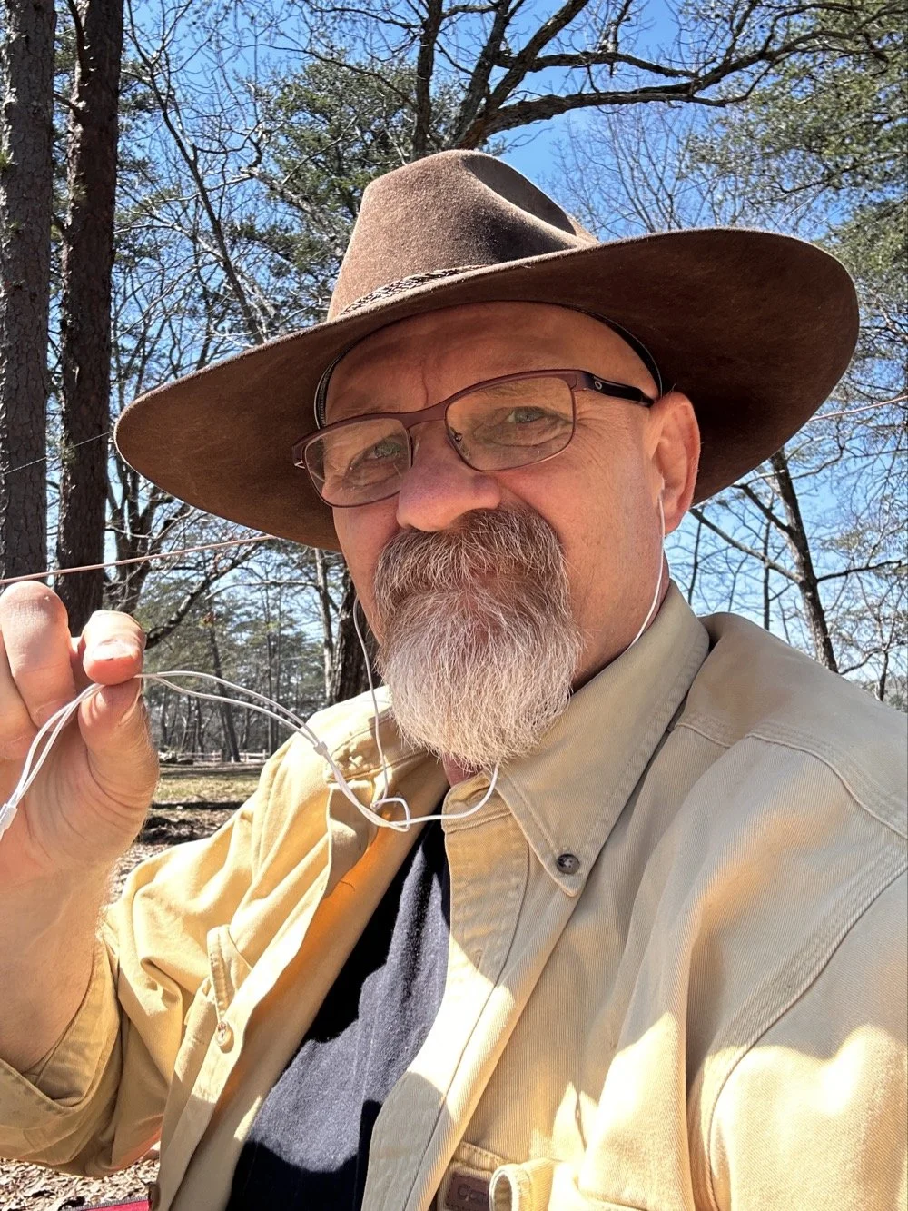
David - WK4DS resorting to headphones due to high noise in the local environment during POTA at Cloudland Canyon State Park
By this point I had almost 80 QSOs in the log so I set a goal of getting 80 counted QSOs to go towards my goal of 10,000 which meant accounting for the dupes in my log, of which there were many today. You see I had been there for several hours at this point and some stations had wandered by me a couple of times. I know I worked one station 3 times today, but so is life sometimes. I no longer tell people I have them in the log, I automatically assume one of two things have happened.
The first one is that I could have gotten someone else’s call wrong and therefore I now have the legitimate call on the hook at that moment. (very possible with my poor hearing at times) The second is that they simply don’t realize I have them in the log. So I work them again and log it again and simply let HAMRS record it as a dupe and move on with life. It doesn’t hurt anything to log them again, other than the time it takes, so I simply complete the QSO as if it was the first time. No harm, no foul.
CW and North America came in clutch for this POTA Activator today!
Today saw me work over 80 calls and of those exactly ZERO were outside of North America. I worked a couple of Canadians but other than that, the rest were US operators only. Not a single DX station at all. It could be one or more of several factors I guess. I did put over 80 calls in the log for today and that is a great day despite all the various things that attempted to stop me. haha. In the end, it was still a wonderful day and I had a great time with my tiny little Penntek TR-35, my Begali Traveler CW Paddle and the Reliance EFHW 40 meter antenna. What a great little setup! Portable, light weight and best of all, it works! What do the old timers say? “Five watts and a wire…” Yeah, it will absolutely work if you will go when the bands are open and just try…
You can help support this website by using these Amazon Affiliate Links:
QRP/Portable Radios:
Antennas & Tuning:
CW Equipment:
Power & Accessories:
Organization & Transport:
BONUS ITEMS
72 - WK4DS (David)
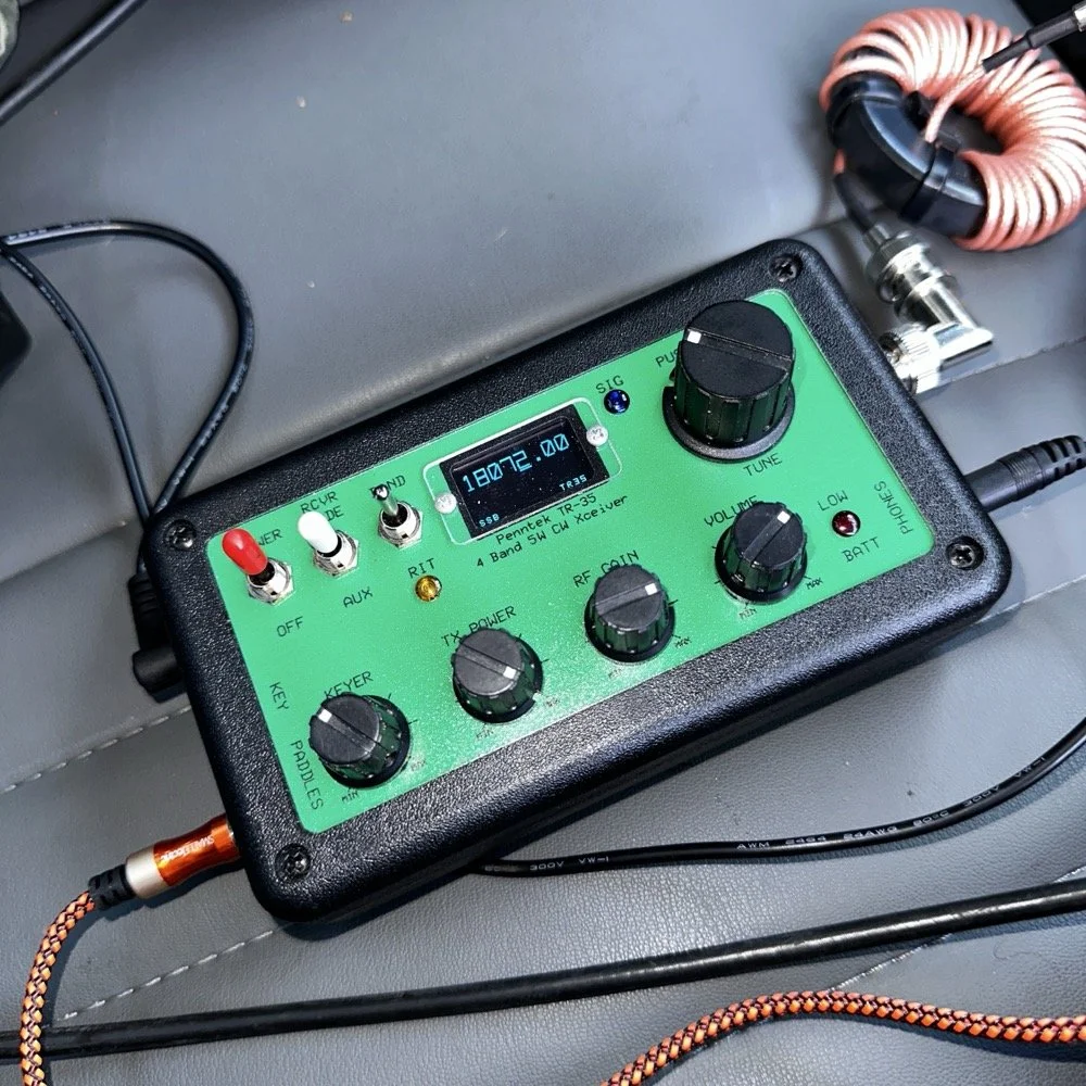
Penntek TR-35 QRP power, DX & POTA fun!
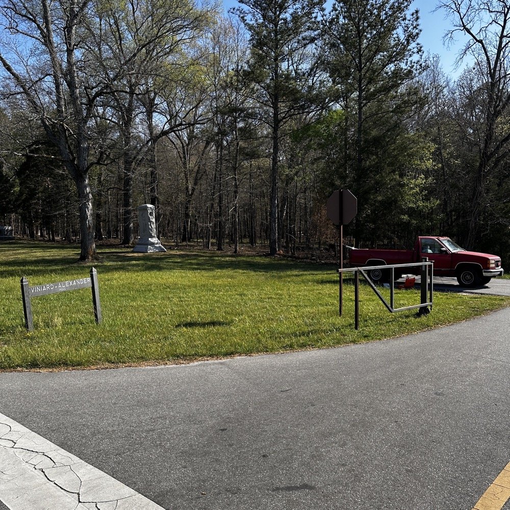
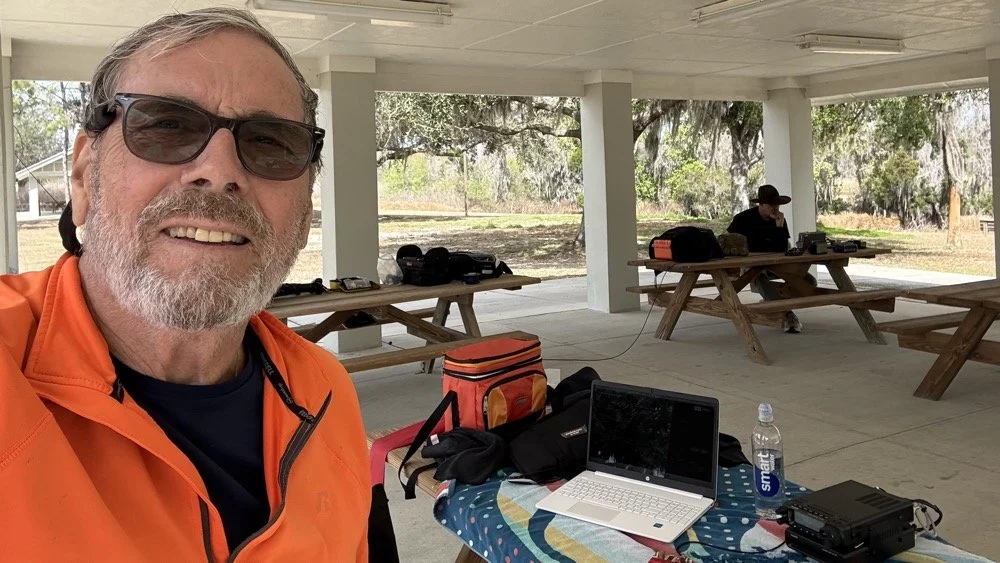
Today saw me back in north west Georgia and back at US-2169 (Cloudland Canyon State Park) for a quick little QRP activation. I deployed the Penntek TR-35 QRP HF Transceiver today as it is simple, compact and fun to use…as long as you like CW. This is because it is a CW only radio…haha. One of the things I love about this particular park though, is the fact that it has so many different places to setup a POTA station and not be in anyone else’s way. Today saw me deploy to the top of the hill at the Frisbee golf course (which happens to be my all time favorite place to deploy when at this park) and setup the telescoping vertical on the truck receiver hitch mount that I made. Since this location is in direct sun most of the time, I opted to set the radio up in the cab.
Cloudland Canyon State Park - US-2169 POTA Destination
Today saw me back in north west Georgia and back at US-2169 (Cloudland Canyon State Park) for a quick little QRP activation. I deployed the Penntek TR-35 QRP HF Transceiver today as it is simple, compact and fun to use…as long as you like CW. This is because it is a CW only radio…haha. One of the things I love about this particular park though, is the fact that it has so many different places to setup a POTA station and not be in anyone else’s way. Today saw me deploy to the top of the hill at the Frisbee golf course (which happens to be my all time favorite place to deploy when at this park) and setup the telescoping vertical on the truck receiver hitch mount that I made. Since this location is in direct sun most of the time, I opted to set the radio up in the cab.
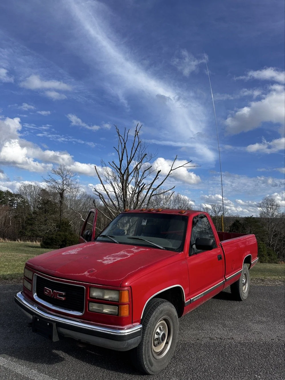
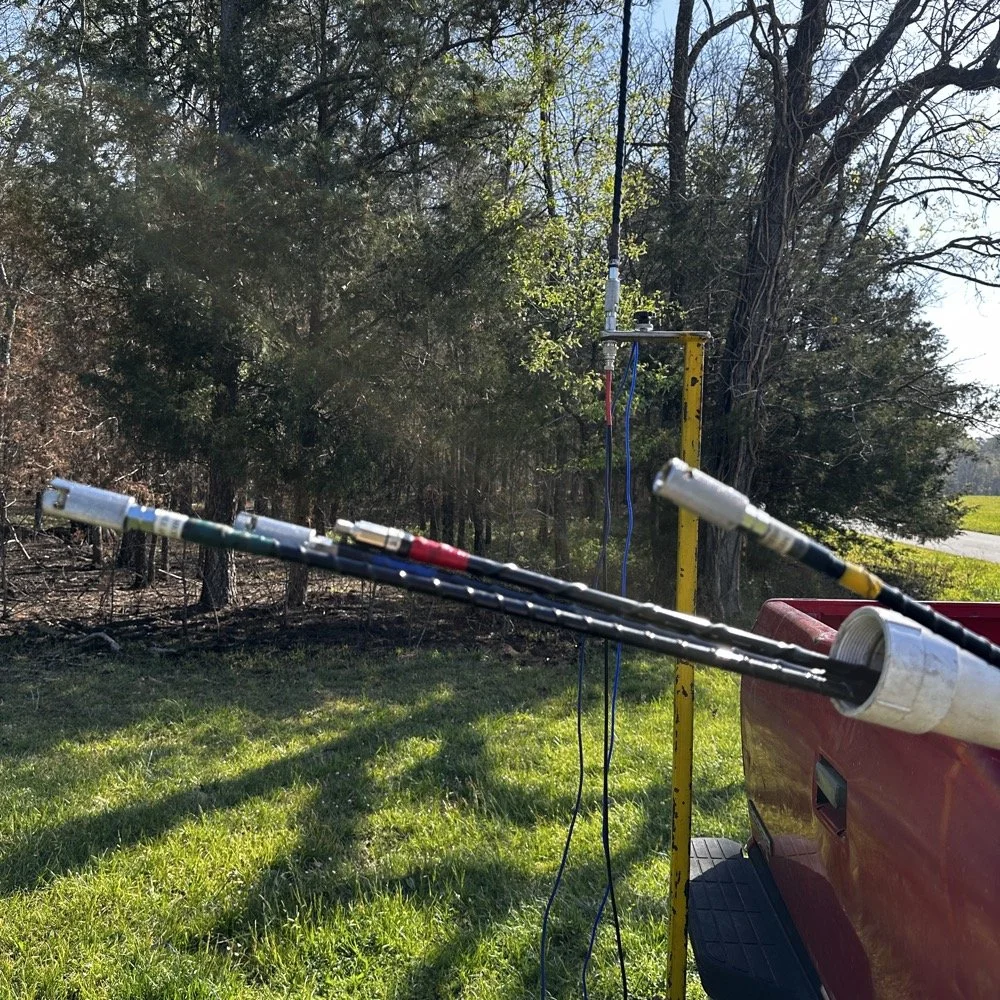
The old red chevy is back in service as the War Wagon is down currently with several problems. Today saw me setup the 18.4’ telescoping vertical from Amazon.
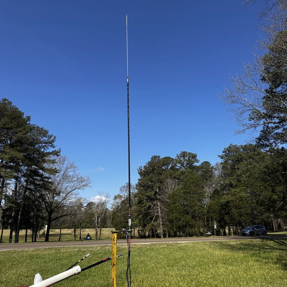
Setting up the 18.4’ Telescoping Vertical Antenna on 20m
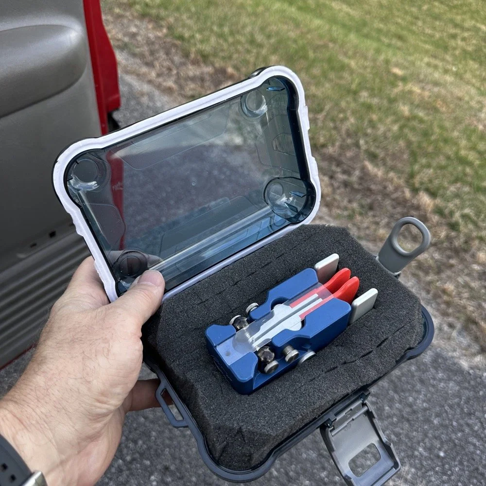
Tuning is simple with my old friend the nanoVNA. I have learned to simplify my tuning process to the following. I will setup the antenna and collapse the first section at the top as it never ends up being needed unless I go below 20 meters. Then I deploy the two usual radials and connect them to the ground lug on the antenna base. Then I connect the nanoVNA to the base of the antenna with a short coax jumper and power on the nanoVNA. I have mine set to power on with the span set from 1mhz to 30mhz and you will immediately see the null where the antenna is tuned somewhere in the middle. Then I choose the menu for the marker and set the marker to minimum and then check the “tracking” box so it will follow the null. When you do this, the marker will display the center of the tuned frequency at the top of the nanoVNA. Now all you do is start shortening the antenna a little at a time till the frequency moves up to about 14.050mhz and your done! I happen to be just tall enough to be able to reach to first collapsible section on the antenna while it is still mounted and I can simply slide it down a little at a time without having to take it down to do it. This whole tuning process takes maybe two minutes now that I have done it so many times. It goes really fast. With the antenna built and tuned to 20 meters CW (today I couldn’t get the SWR below 1.5:1 for some reason but as you will see later, that is not a problem), I turned my attention to the radio side of the build out…
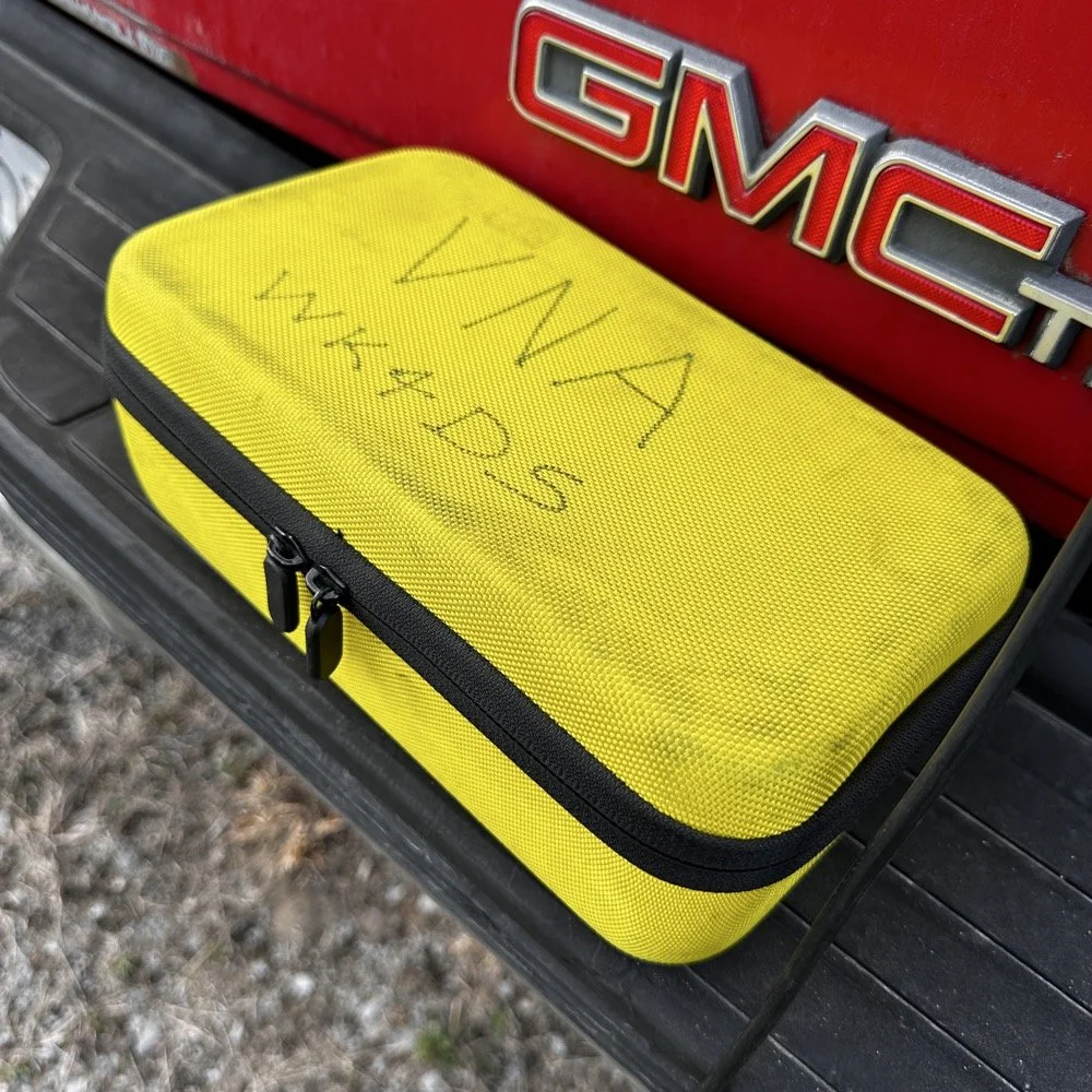
The GigaParts soft shell case is a great way to store a nanoVNA and all the cables and adapters you will collect for it.
Quick side note… I have FINALLY bought a hardshell case for my Begali Traveler CW paddle! I found this little case at Walmart if I remember right and the foam was left over from the Harbor Freight hard shell case for the Scout 555 I bought recently. I guess it pays to hold on to the scraps on occasion…haha. I have about gotten to the point where I dont save stuff like this foam, but for some reason I held on to this one. I really love this key and it have become the de-facto key I use as long as I have a hard surface to sit it on. I have retired my N3ZN key that I got from Tony a while back to my camper key and it now lives with my TenTec Argonaut V permanently in that capacity. I still deploy with three keys most of the time and if I don’t bring the Penntek TR-35 then I will have two keys. I will get into all that later, but for now, lets keep setting up the radio.
I finally procured a storage solution for my Begali Traveler CW paddle so it doesn’t get damaged between POTA park activations.
Pros and Cons of the Penntek TR-35 QRP Transceiver
Below is the star of the show…the Penntek TR-35 4 band QRP HF Transceiver. This little radio sports the following features which make it perfect for POTA field ops.
It is small and light weight.
Output power is a full 5 watts and adjustable down from there.
Three filters he calls SSB(VERY wide), CW wide and CW narrow. I think CW narrow is 500hz or a little less as it is really selective.
Two keyer memories that are easy to program once you get the cadence down.
4 HF bands (40m, 30m, 20m, & 17m) The radio only toggles up through the bands with the band switch. Simple and effective.
RIT which is de-facto split if you need to work a split station. It also helps me when someone is off a couple hundred hertz as well.
VFO has three speeds for the tuning. The default two are past the decimal and a long press on the VFO will set it to 1 khz tuning which is really fast for the CW portion.
There is a physical RF Gain AND a Volume knob!!! That is awesome on a whole different level by itself.
The keyer speed is set by a knob so speed changes for different POTA hunters is easy and fast. I really like this feature.
It has a straight key input as well as a paddle input so you are ready to go with either kind of key.
Some detractors that I wished were different are…
I really wished it had 15 meters instead of 17 meters…but I digress…
It is so small that there is no room for a speaker so you must use some sort of external speaker whether it be earphones or something like what I used today.
It lacks an S meter and this bothers me so much that I built one just for it. Link is here to that article…
That is about it for what I dont like, it is almost perfect.
The Penntek TR-35 HF QRP transceiver is almost perfect, it is so close I wouldn’t change it now if I could. It really has everything you need and nothing you don’t to run a POTA activation.
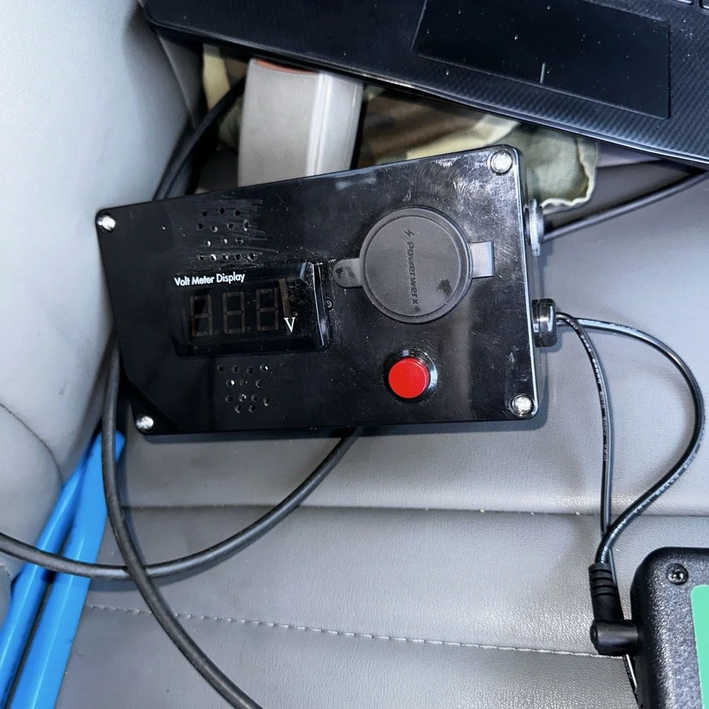
Homebrew power pack containing a Bioenno 3Ah LiFePO4 battery, speakers and a "on demand" voltmeter with a pair of Anderson power pole connectors
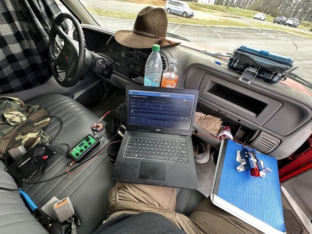
This is the station for today. Dell Inspiron computer, Begali traveler paddle, Penntek TR-35 QRP radio, and a POTA park!
POTA Station Positioning and Start Up
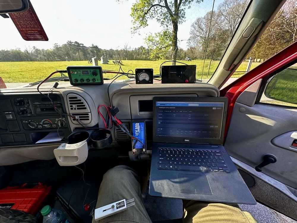
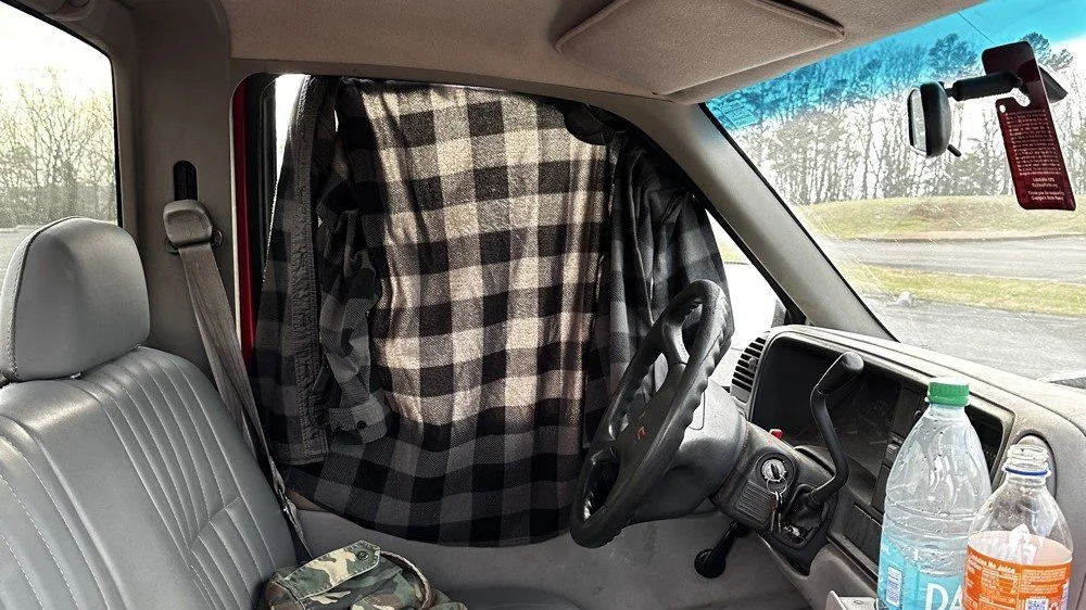
Once I finished connecting all the RF equipment together, I had to figure out where I would sit. I had not really considered this as my regular truck has that huge, flat arm rest that I normally have access to. With that considered, I decided to setup in the passenger seat as this made the most logical sense. Then I had the problem of the sun causing me a ton of glare and I had to come up with something to mitigate it. The below photo is my expedient “curtain” that I simply rolled up in the window. Modern problems call for modern solutions… lol.
Once the sun was beaten back out of the cab of the truck, I had to figure out how to setup up the whole station so that I could send code and log the contacts as well. What you see is how I solved that problem, I just balanced the computer on one leg and the clip board is cheated. The clip board is actually sitting on the top of the open glove box, which is stabilizing it, and then it is making the third contact on my leg which turned out to be very stable for the cw key. The Begali Trraveler is one of those keys that once you get it set like you want, it is simply a dream to use. I have learned that it takes me a few minutes to get it positioned properly or I will make a lot of mistakes with it. But once I get it in the right spot, it just works.
Simple problems require simple solutions, this is how I removed the sun glare off of my radio and computer screen today. If it works…
Activation Report: The Penntek TR-35 and 5 watts of RF Power
Once I had the station sorted out, I powered up the rig and hunted me a clear frequency, today the 20 meter band was going strong so the band was a little crowded. I would call QRL (This means “Is the frequency in use?”) and I would hear a lone “R” come back to me. This means someone is using it so I would simply dial to another frequency and try again. I finally found a clear spot and listened for a bit as sometimes you are on the other side of a station that is talking to someone you can not hear and they are listening to them at the time you get on frequency. So it is a good idea to listen for a while before sending QRL to make sure this is not happening. I didn’t hear anything and after calling QRL again, I started calling CQ POTA… Then things took off…
The log for this activation came together really nicely, and I was pretty happy with how the bands cooperated. All 36 contacts were CW at 5 watts QRP from US-2169, split between 20 meters and 17 meters.
I started on 20m at 14.061 and the pile-up got going almost immediately. The contacts came in steadily from all over the place -- Illinois, Vermont, Michigan, Missouri, Maryland, North Carolina, Texas, and more. A couple of Canadian stations made it into the log too, with VE3UXJ and VA3EKR both pulling through with solid enough signals to complete the exchange. Signal reports on 20m were mostly in the 559 to 599 range, which honestly is about as good as it gets when you are running 5 watts into a field antenna. Also remember that this radio lacks that S meter I like to have…so the signal reports were a bit more subjective today compared to other days.
After working through the 20m pile-up, I switched over to 17m at 18.072, and that is where things got really interesting. The band was in good shape with minimal QSB and the contacts kept coming. It did take a few minutes of calling CQ to get the RBN (Reverse Beacon Network) to auto update my spot on the spot page of the POTA website, but once it did, things started looking up! I picked up stations from Idaho, Florida, Colorado, Washington, and Texas, among others. But the two that really stood out were HI8D out of the Dominican Republic and JH1OCC from Japan! Getting Japan in the log on 5 watts from a field activation is always a treat, and the fact that JH1OCC came back at all through the noise is a testament to how well 17m was performing this afternoon. His received signal report was a 339, which is pretty typical for a trans-Pacific path at QRP, but a contact is a contact and I will absolutely take it! This has happened to me a few times now while doing POTA, I will be on one of the upper bands and a band opening to the Far East will open up for a couple of minutes and I will land one or two Japan calls. It takes me a minute to process this sometimes, as it is a long way to Japan from NW Georgia!
Total QSO count landed at 36, which is a solid activation by any measure. Both bands contributed meaningfully, and the geographic spread across the log -- from the Midwest out to the Rockies, up into Canada, down to the Caribbean, and all the way to Japan is one of those things that never gets old no matter how many activations you do. Five watts and a wire…errr…vertical…lol…, doing its thing. This setup worked pretty well but if I could improve it, I would make a more steady surface for the key. The key moved around too much for my liking so I would like to correct that going forward, like maybe use a different key…lol. Anyway, it was a great day in the park and I hope this nudge you to get out and activate a park near you.
You can help support this website by using these Amazon Affiliate Links:
QRP/Portable Radios:
Antennas & Tuning:
CW Equipment:
Power & Accessories:
Organization & Transport:
BONUS ITEMS
73, David / WK4DS
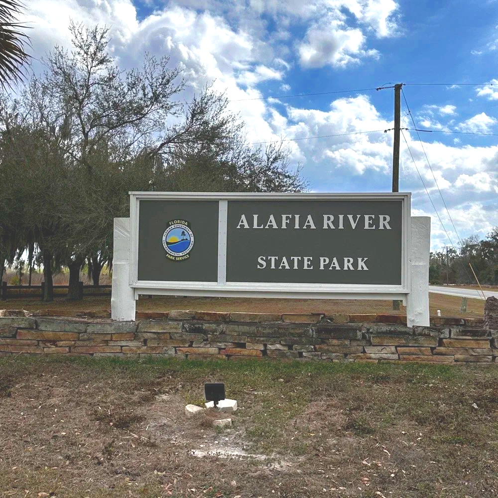
Alafia River POTA: How 12 Meters Delivered 72% DX While Everyone Else Fought on 20m
Everyone defaults to 20 meters for POTA. It's crowded, competitive, and honestly…boring at this point. So at Alafia River State Park (US-1829), I did something different: I skipped 20 meters entirely and focused on 12 and 15 meters instead. The result? A 72% DX rate on 12 meters, contacts to 10 different countries in under an hour, and some of the best propagation I've experienced from a Florida state park. All at 10 watts.
Everyone defaults to 20 meters for POTA. It's crowded, competitive, and honestly…boring at this point. So at Alafia River State Park (US-1829), I did something different: I skipped 20 meters entirely and focused on 12 and 15 meters instead. The result? A 72% DX rate on 12 meters, contacts to 10 different countries in under an hour, and some of the best propagation I've experienced from a Florida state park. All at 10 watts.
Let me show you why 12 meters is the band everyone's ignoring while they pile up on 20m.
Why I Skipped 20 Meters Entirely
Look, I get it. 20 meters is the default POTA band. It's where everyone goes, it's where the hunters expect you to be, and it's reliable. But reliable also means crowded, and crowded means QRM, pile-ups, and fighting for frequency space with a dozen other activators doing the same thing.
We're near solar cycle maximum right now, which means the higher bands (10m, 12m, and 15m) are performing like 20m used to during previous cycles. But most POTA activators haven't adapted their band strategy yet. They're still automatically going to 14.061 MHz CW or 20m SSB without even checking what's happening higher up in frequency.
So today at Alafia River State Park with Chas (who was also activating), I made a conscious decision: skip 20 meters completely. Start with 12 meters, see what happens, then move to 15 meters. If those bands produced nothing, I could always drop to 20m as a backup. But I had a feeling 12m was going to surprise me.
Spoiler: it absolutely did.
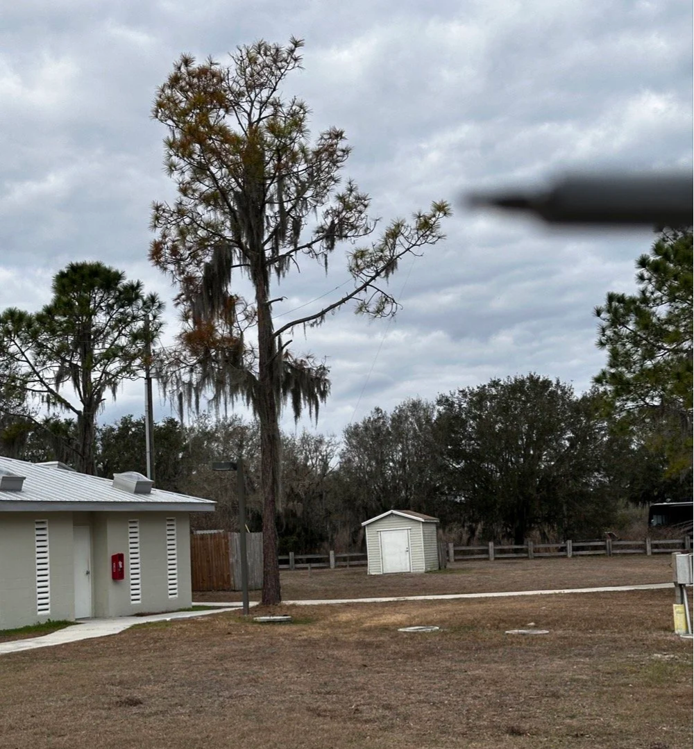
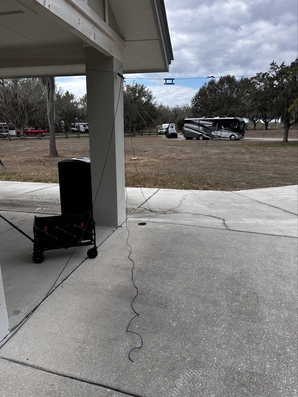
The Alafia River State Park Setup
Alafia River State Park is designated US-1829 for POTA and it's located in Lithia, Florida, just southeast of Tampa. The park has a really nice covered pavilion with picnic tables, bathrooms, and RV camping area with good tree coverage. Spanish moss everywhere, typical Florida scrub vegetation, and plenty of tall trees for wire antennas.
The covered pavilion where we set up for the activation. Clean facilities, picnic tables, and good tree coverage for wire antennas.
Chas and I both set up under the pavilion, him at one table, me at another about 20 feet away. This gave us enough separation to avoid too much RF interference between our stations, though we still had to coordinate who was transmitting when to avoid stepping on each other.
My antenna setup was a 65 foot random wire thrown up into one of the larger trees near the pavilion. I'm guessing it got maybe 30-35 feet up into the branches, which isn't spectacular but it's what I could reach with the available trees. The radiator came down to the tuner that is tied up high on the corner column of the pavilion. I also used a larger set of radials so the antenna would be more likely to work on 40 meters. But that didn’t seem to matter as I would come to find out…
This is the tree branch I had my wire antenna ran out to, if you look close, you can see the wire antenna in the photo.
Now here's where I need to be honest about the equipment struggles today... I am not immune to making common, simple mistakes and here are a couple from today that I actually did. I started out on 40 meters and wanted to work some stations there since it was supposed to be about 9:30 when I would be starting the activation. Well, that isnt how it went at all. I started out usng the Elecraft T1 antenna tuner with the sBitx. This turns out to be a problem though, you see JJ and the team added a high SWR protection script in the new code and if the SWR goes over 3 to 1 then it automatically turns the output power all the way down to prevent it from killing the finals. Well, it seems that as the Elecraft T1 goes through the tune process, the SWR will rise above 3:1 and this shuts off the RF from the radio and the tuner cant finish the tune…
Elecraft T1 Antenna Tuner with wire antenna and ground radials tied to pavilion column.
But before I figured this out, there is another small detail… The sbitx tune feature is simple, hit a button and it will “dead key” the radio and hold that for a time. Both the level of power and the time are adjustable in the menu so I set it to 20 seconds and the level to about 5 watts as the T1 is a QRP tuner. The Elecraft T1 can tune about anything you want to use for an antenna to a usable SWR so I was confident in the little tuner. Soooo, I would hit the tune button on the sBitx then sprint over to the tuner and hit the button on it to activate the tune feature on the tuner. The tune timer on the sBitx would finish right as I would get back to the radio. I would check it with a Morse code key in CW mode and the radio would and SWR of 5 or 6 to 1 and the output power would be turned all the way down… I would turn the power back up to 5 watts and then try again. I performed this comedy act a few more times before seeing the “SPLIT” button was on and that the B VFO was on 15 meters!
Armed with this knowledge, I confidently turned off split and immediately found myself back to the HIGH SWR alarm on the sBitx… No matter what I did, as soon as the Elecraft T1 would start the tune cycle, it would trip the radio SWR protection feature and this would turn off the transmitter in the radio and by extension, also shut down the tuner mid-tune… Frustrated by this revelation, I found myself getting the Penntek TR-35 out of the bag and using it a couple of times to find out it was doing the same thing! After spending 30 minutes doing this, I finally threw in the towel and just went out to the truck and got my MFJ941 manual tuner and the nanoVNA and connected it in place of the Elecraft unit.
But the fun doesn’t stop here! I could not get this one to tune either! What was going on here!!! Well, it turns out that I had at some point switched the MFJ’s antenna selector from wire to the next antenna port and didn’t check it so I was effectively tuning the SO239 connector on the back of the tuner to 40 meters!!! Good grief, this has been a mess! Once I figured this out and set the tuner to the correct antenna, it tuned up almost instantly. This whole debacle took over an hour to sort out, so if you think you are not very good at POTA setup and breakdown because you see these “old pros” doing it effortlessly, just know we are not immune to errors and odd problems either…haha.
Back to the rest of the activation report…
Radio-wise, I was running the sBitx v3 at 10 watts maximum. For those not familiar with QRP POTA operations, 10 watts is pretty normal power level, it is about 1/10th of what most people run. But it's what the sBitx puts out reliably on all bands and that is well within the Elecraft T1 tuner’s power handling capability (remember, I had started with this tuner), and honestly, with propagation conditions this good, power isn't the limiting factor anyway.
I had my Dell laptop for logging contacts in HAMRS (the POTA logging software), a foldable keyboard because typing on a laptop in bright sunlight is annoying, a CW paddle, and the usual field gear—water bottle, clipboard with paper log backup, etc. Pretty standard POTA kit.
12 Meters: The Band Everyone's Ignoring
I fired up the sBitx on 12 meters around 1600 UTC (11:00 AM local time) and started calling CQ on FT8 at 24.915 MHz. Within seconds, I was getting responses. And not just USA stations, I'm talking Greece, France, Netherlands, Spain.
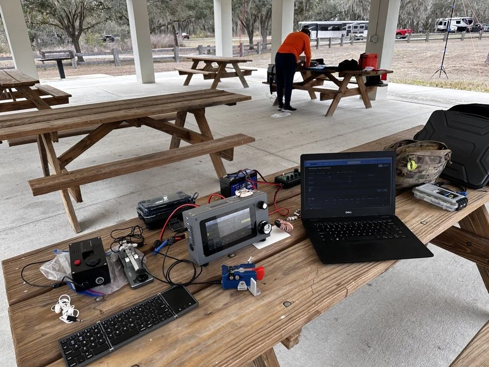
The station: sBitx v3 running 10 watts, MFJ-941 manual antenna tuner, Dell laptop for logging, Begali Traveler CW paddle, and field keyboard. This setup delivered 72% DX on 12 meters today!!!
The first contact was PB2A in the Netherlands at 1620 UTC. Signal report was strong both directions. Okay, that's promising! 12m is open to Europe!
Next contact: EA5KB in Spain at 1622 UTC. Also solid copy.
Then SV1GYN in Greece at 1626 UTC, followed by SV8EFJ (also Greece) at 1631 UTC.
This is when I realized 12 meters wasn't just "open" to Europe it was absolutely on fire! In the next hour, I worked:
Three stations in Greece (SV1GYN, SV8EFJ, SV7FDA)
Two stations in France (F4IFO, F6BIA)
Spain (EA5KB)
Netherlands (PB2A)
Portugal (CT1FIU)
Czech Republic (OK1DTC)
Poland (SP2GCJ)
Plus Brazil, Dominican Republic, and Canada as bonus DX
That's 10 different countries in less than an hour on 12 meters. With 10 watts. From Florida. To put this in perspective: of the 18 contacts I made on 12m, 13 were DX (non-USA). That's a 72% DX rate.
When was the last time you heard anyone report a 72% DX rate from a POTA activation? This is why solar cycle maximum matters, and this is why you should check 12 meters before defaulting to 20m.
The propagation held solid from about 1606 UTC until around 1657 UTC when it started to fade. That's nearly an hour of wide-open conditions to Europe from a Florida state park with a wire antenna and 10 watts. Just... chef's kiss (I saw someone else use this term and it absolutely applies here, lol). This is what amateur radio is supposed to be.
15 Meters: The Reality Check
After 12 meters started fading around 1700 UTC, I switched to 15 meters to see if the party was still going. Spoiler: it was not.
15 meters wasn't dead as I made 10 contacts between 1738 and 1748 UTC but the DX had evaporated. Out of those 10 contacts:
8 were USA stations (domestic)
2 were Germany (the only DX and were way down in the noise)
That's a 20% DX rate on 15m compared to 72% on 12m. The contrast was striking and immediate. As soon as I moved from 24 MHz to 21 MHz, I went from European pile-ups to mostly USA stations.
This isn't a knock on 15 meters, it's just propagation and we all know how the sky likes to mess with out brains…. By late afternoon (1730-1800 UTC), 15m was transitioning from long-skip DX to shorter-distance USA contacts. Which is fine if you need domestic QSOs to reach your 10-contact activation threshold, but if you're chasing DX, 12m was clearly the better choice earlier in the day.
The lesson here: timing matters just as much as band selection. 12m was the star of the show from 1600-1700 UTC. 15m was better for domestic contacts after 1730 UTC. If I'd started on 15m at 1600, I probably would've missed the entire European opening on 12m.
The 40m and 10m Bookends
I also made a few contacts on 40 meters and 10 meters to round out the activation, mostly just to see what those bands were doing.
40 meters (4 contacts): Mostly short-skip USA stations. Nothing surprising here as 40m in the afternoon is for regional contacts. It works, it's reliable, but it's not going to give you Greece with 10 watts and a random wire thrown over a tree branch.
10 meters (4 contacts): Had a brief opening but nothing like 12m. A couple of USA stations and some Caribbean/Central America. 10m can be spectacular during solar max, but today it was just "okay." You could just watch the stations fade in and out on the band here on the waterfall…
Final tally for the activation:
Total: 36 QSOs
12m: 18 QSOs (50% of total) - 72% DX rate
15m: 10 QSOs (28% of total) - 20% DX rate
40m: 4 QSOs (11%)
10m: 4 QSOs (11%)
Modes: 50% CW, 50% FT8
Twelve meters did half the work and delivered nearly all the DX. That's the story.
Operating With Chas: Multi-Operator Coordination
Chas (NA2B) at his operating position with me in the background. Multi-operator POTA setup at Alafia River State Park—he's about 20 feet away to minimize RF interference.
Chas was set up about 20 feet away at another picnic table under the same pavilion, also activating US-1829. We coordinated our operating so we weren't transmitting on top of each other. He started on 30 meters since I was on 40 and after I finished on 40, I jumped all the way to 12 meters so he could move slowly up the band through 20 then 17 and even 15 before he got his 60 and called it a day. He runs 50 watts currently and has great success with it, but the QRP bug has bitten him and he is going to be turning down the power dial soon… or so he says… haha
This coordination is important for multi-operator POTA setups. You can absolutely operate two stations simultaneously from the same park, but you need enough physical separation to avoid RF interference (20-30 feet minimum), and you need to pay attention to who's transmitting when. If both operators key up at the same time on different bands, you'll hear it immediately as front-end overload or mixing products.
It actually works out pretty well though, you have someone to talk to between contacts, you can share band information ("hey, 12m is wide open to Europe right now"), and if one operator needs help with something technical, the other person is right there. Plus it makes the drive more enjoyable when you're carpooling to the activation site (which we didn’t do this time, but this point is still valid). All of this and it is just plain fun to hand out with a like minded person for a while and just have the fellowship.
Chas and I have done several multi-op activations now and we've got the coordination pretty well figured out. As long as you're mindful of the RF environment and don't step on each other's transmissions, it's actually a really fun way to do POTA.
Lessons for Other POTA Activators
If you take away one thing from this activation, let it be this: check 12 meters before you default to 20 meters.
Most POTA guides and YouTube videos focus on 20m and 40m because those bands are "reliable." And they are! You can almost always make contacts on 20m or 40m during a POTA activation. But reliable isn't the same as optimal…or fun..
We're at solar cycle maximum right now (or very close to it), which means the higher bands—10m, 12m, and 15m—are performing better than they have in a decade. But those bands are only open during certain times of day, and you have to actually check them to know.
Here's my recommended POTA band strategy for 2025-2026:
1. Start with 12 meters during daylight hours (1500-1900 UTC / 10 AM - 2 PM local) Check FT8 on 24.915 MHz or CW around 24.900-24.910 MHz. If you see European or South American stations, stay there. Don't move until the band fades.
2. If 12m is dead, try 15 meters next Same time window. 15m opens a bit earlier and stays open a bit later than 12m.
3. If both higher bands are quiet, then drop to 20 or 17 meters You haven't lost anything by checking 12m and 15m first, it only takes 5 minutes to scan FT8 and see if there's activity. But if you skip straight to 20m, you might miss the entire European opening on 12m.
4. Add 40 meters in the evening or early morning 40m is your regional workhorse. Use it to fill in USA contacts if you need to reach your 10-QSO activation threshold.
5. Keep an eye on 10 meters during solar max 10m can be absolutely bonkers during cycle peaks. Sometimes it's dead, sometimes it's a highway to Japan. Worth checking.
Key point: Solar cycle conditions change everything. The band strategy that worked in 2019 (solar minimum) doesn't apply in 2025 (solar maximum). Adapt your approach, check the higher bands first, and you'll be rewarded with DX that most POTA activators never experience because they're stuck in the 20m/40m routine.
The "Skip 20m" Strategy: Does It Always Work?
Okay, let's be realistic here. Will 12 meters always deliver 72% DX rates? No, of course not. Propagation is fickle, solar conditions vary day to day, and sometimes the higher bands are just dead. The sun giveth and the sun taketh away.. lol.
But here's the thing: you don't know until you check. And checking takes 5 minutes to tune to 24.915 MHz on FT8, watch the waterfall for 1 minute, and see if you're decoding any DX stations. If it is a yes, start calling. If no, move down to 20m like you were going to do anyway.
The worst-case scenario is that you "waste" 5 minutes checking a dead band and then go to 20m as your backup. The best case scenario is that you find a wide open band to Europe with zero QRM and work 10 countries in an hour with 10 watts.
I'll take that bet every time.
Also worth noting: 12 meters is way less crowded than 20m. On 20 meters during a weekend, you're competing with dozens of other POTA activators, contest stations, and regular QSOs. On 12 meters? Most of the band is empty. You can call CQ on an open frequency without worrying about stepping on someone else, and when DX stations hear you, you're often the only POTA station they can work on that band.
Less QRM, better propagation, higher DX percentage, what's not to love?
Alafia River State Park: Worth Activating?
As for US-1829 specifically: yeah, it's a nice park. The covered pavilion makes POTA operations comfortable even in Florida weather (sun, rain, whatever), the facilities are clean and modern, there's RV camping if you want to stay overnight, and the trees provide decent antenna support.
It's about 30 minutes southeast of Tampa, so it's accessible if you're in the area. Not a destination park like some of the big state parks, but definitely worth activating if you're looking for a Florida POTA location that isn't mobbed with tourists.
The tree I used for the 65-foot random wire was a large pine tree of some variety with good height and thick branches for support. Spanish moss everywhere, typical Florida landscape. Got the wire up to maybe 30-35 feet, which is serviceable if not spectacular.
One note: there were RVs parked in the camping area about 100 feet from the pavilion, so we weren't completely isolated. Nobody bothered us though, and one RV owner came over to chat about amateur radio for a few minutes. Friendly folks just out camping.
Best time to activate: Late morning to early afternoon (local time) if you want to catch the 12m European opening. Earlier in the day if you want 40m to be productive for longer distance USA contacts.
Facilities: Bathrooms, covered pavilion with tables, RV camping, paved parking. Bring your own food/water.
Antenna options: Plenty of trees for wire antennas. A vertical would work too if you prefer.
Final Stats and Conclusion
Let's wrap this up with the numbers:
Total QSOs: 36
12 meters: 18 QSOs (50% of total) - 72% DX rate
15 meters: 10 QSOs (28%) - 20% DX rate
40 meters: 4 QSOs (11%)
10 meters: 4 QSOs (11%)
DX Worked: 12 different countries
Greece (3 QSOs)
France (2)
Germany (2)
Brazil (2)
Plus Spain, Netherlands, Portugal, Czech Republic, Poland, Canada, Dominican Republic, US Virgin Islands
Modes: 50% CW, 50% FT8 Power: 10 watts QRP Antenna: 65-foot random wire at about 30-35 feet
The takeaway: 12 meters is the secret weapon for POTA DX during solar cycle maximum. While everyone else is fighting on 20 meters, you can have an entire band nearly to yourself with better propagation, less QRM, and DX rates that would make any contester jealous.
So next time you're setting up for a POTA activation, do me a favor: check 12 meters first. You might be surprised what you find.
Thanks and get your radio out!
Have you worked DX on 12 meters during POTA activations? What bands are you checking during solar max? Drop a comment! I'd love to hear what's working for you.
You can help support this website by using these Amazon Affiliate Links:
QRP/Portable Radios:
Antennas & Tuning:
CW Equipment:
Power & Accessories:
Organization & Transport:
BONUS ITEMS
73, David / WK4DS
Smith Charts are easy…(The basics of antenna matching.)
When I decided to learn about Smith Charts and how to use them, I had no idea what a giant rabbit hole that was going to be. I have learned so much more since writing that first blog post about them that I wanted to revisit it and share some information with my readers. I love to learn new things and for some reason I have never taken the time (till recently that is…) to learn how to even read a smith chart, much less how to use them to design ANYTHING!
When I decided to learn about Smith Charts and how to use them, I had no idea what a giant rabbit hole that was going to be. I have learned so much more since writing that first blog post about them that I wanted to revisit it and share some information with my readers. I love to learn new things and for some reason I have never taken the time (till recently that is…) to learn how to even read a smith chart, much less how to use them to design ANYTHING!
The nanoVNA: A Vector Network Analyzer for everyone!
I started down this path with looking at antenna data from one of my POTA antennas on the nanoVNA. The nanoVNA is one of those wonders of modern technology that has become accessible to the masses recently. You see, before a few short years ago a VNA (Vector Network Analyzer) would easily run in the 5 figures and some of the nicer ones would break 6 figures. Rohde and Schwarz come to mind here… Even their used ones trade today for thousands of dollars…
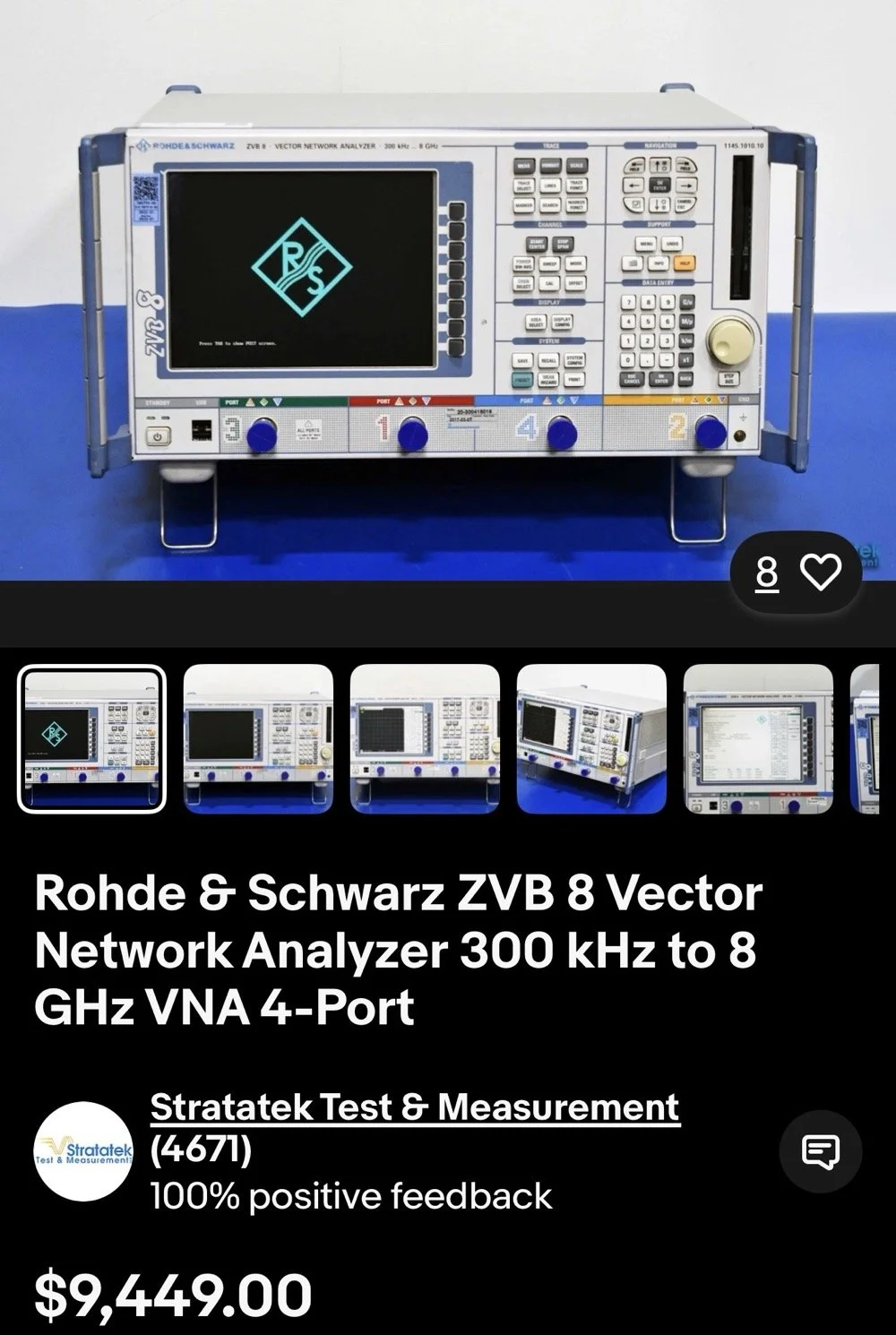
This is the reality of VNAs from just a couple of years ago. 4 and 5 figure prices for used units were common.
The nanoVNA changed all of that. It is small, runs on Linux and is now a single board computer in a tiny battery powered device that will literally sit in the palm of your hand. I have used one for my antenna setups for a couple of years now. I am actually on my second unit as the first one developed a fault and it was so inexpensive that I just bought a new one and threw the old one in the trash. You won’t see that happening with an HP / Agilent VNA!
There is a very good reason I use one for my antenna tuning needs too. The nanoVNA does everything those larger (and more expensive as well) ham radio specific antenna analyzers do that are available. You just have to learn a little more on how to use the nanoVNA. It also will perform functions that the antenna analyzers will not and this is where I love to bring the nanoVNA into the light. It has a smith chart function as well as an S21 input option that most, if not all ham radio antenna analyzers lack. You simply can not sweep filters with a MFJ antenna analyzer, at least not that I am aware of. This is where I found smith charts as I started to want to know what it was showing me on those charts. All of these nanoVNAs have a smith chart function and it is normally “on” when you start them up by default.
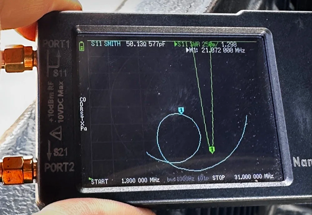
nanoVNA showing the Smith chart upon power up. Notice the diminutive size of the device compared to my fingers!
Smith Charts are NOT Scary…
In the above photo, the light blue trace is the one for the smith chart view. If you look really close, you can just barely make out the circular plot of the smith chart graph and in slight less illumination it does show up better. The light blue curved line represents the plotted values from 1.8 mhz up to 31 mhz (the two values are at the bottom) and you can move a marker along this plot as you go through that frequency range. In this photo I have stopped at 21.072 mhz as I was tuning my telescoping vertical to the 15 meter band to operate CW and FT8. It shows two more pieces of critical information though, the real reactance and the imaginary reactance..yes, imaginary… On these little nanoVNAs it shows up as either inductance (+j value when converted) and capacitance (-j value when converted). This antenna is measuring 50.13 ohms 577pf capacitive. We would need to convert this capacitance to a j value before we can plot it on the smith chart. I will get into that a little later in this article, but for now, this is a great tool if you are wanting to learn how smith charts work and I recommend you get one of these little wonders of technology for yourself and learn how to use it, even more so if you choose to use my link here to get it! As buying it from the link will help me maintain the website and costs you nothing extra.
One of my early attempts at working with a smith chart, it is covered in errors, but this is how you learn…
This is a plain, run of the mill smith chart (pictured above). This one shows two graphs in one chart. The red is the impedance graph and the blue one is the admittance graph.
Smith Chart: Understanding some basic concepts
The simple explanation for these two colors are as follows: red lines are series components and the blue are parallel components when you are using the chart for matching impedances between stages of devices. Like between the coax and the antenna as in the example I have drawn above. That is an antenna I use for POTA that I wanted to see what it would take to get it to 50 ohm resistive. (which is the point right in the middle of the chart BTW)
Already, I have given you three tidbits of intel about these charts and we haven’t even drawn on one yet… Another one is that the horizontal line through the middle is pure resistance and you will notice that it doesn’t say 50 ohms at the center, but rather the number 1. The chart is what is called “Normalized”. All this means is that you can assign what ever value you want to the chart and this center point becomes THAT number and all the others are relative to that value. Maybe you had two stages in an amplifier circuit that are 200 ohm impedance and you want to use this chart to match them, then the center is now 200 and you do simple math to get the other numbers from that point. Like the number 2 (moving to the right, remember we are using the red lines right now) will become 400 ohms as a result. Basically all the numbers are multipliers of the center value you assign. It really is that simple.
Fun fact: All the values below the resistive center line are capacitive and all the numbers above the line are inductive. So when you see one of those weird numbers like 117-j68 This is the “complex” impedance…duh, it even looks complex…haha. But to put it on the chart, it has to be what is called “normalized” and this simply means that you divide the first AND the second number by whatever you assigned to the center of the chart. For most ham radio and especially ham radio antenna stuff, this is 50 ohms. So this complex impedance normalized will be 117/50=2.34 AND 68/50=1.36. BUT since it is a negative “j” value it will now read 2.34-j1.36. This can be plotted on the smith chart directly now. The first number is ALWAYS found on the center “resistive” line first.Then after this point is found you find the second number on the perimeter ring as you see in the photo below. The reason I started at the bottom and not the top (which has the same exact numbers) is because it has a negative symbol in front of the letter “j”. If it is negative, it always goes in the bottom half and if it is positive, then it goes in the top half.
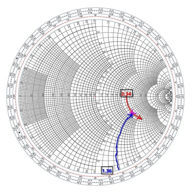
Smith chart showing the initial plot for the value 2.34-j1.36 and how to find it.
Then you simply follow the circular lines from each number out to where these two cross and this is your start point on the chart. Now this particular smith chart only shows the impedance curves so you need the second half (which is a literal mirror image of this one laid on top of it and in a different color) to be able to do a parallel → series type solution to solve for this. If we didn’t have the other half of the chart then we would never be able to put a component in parallel with the load as that is what the other half of the chart is for. Right now we can only add series components to get us up to the resistive line, but it will only give us the native resistance we started with and only eliminate the j portion of the value if we did that. It still doesn’t solve for the movement we need to get to 50 ohms resistive. I guess we could add a parallel resistor to lower the value, but that is really lossy option and we don’t want to put a resistor in parallel with our antenna, that is just burning RF and not putting it into the antenna. Remember a 50 ohm dummy load presents a perfect match to the transmitter output, but with radiate very little of that energy out to the world, instead it is turning this energy into heat…
Knowing this, the solution would be to add a “shunt” inductor to move the plot point up on the chart till it intersects the 50 ohm curve on the TOP HALF OF THE CHART. Once it intersects this line, we will add a series capacitor to bring the value back down to the center point, thereby matching the two stages perfectly. If this is clear as mud, then watch the video below for a visual explanation of what I just typed as well.
Add to all the stuff thus far the following tip as well, anytime you want to move the plot point up on the chart, towards the center line or above it, then you will use an inductor. By the same token, when you want to move the plot point down somewhere lower on the chart from where you are, you will use a capacitor. If you move along the red lines of the chart then it will be series with the load for either device (inductor or capacitor), if it follows a blue line then the device will be in parallel with the load. The below video by W2AEW does a really great job showing this visually so if you are a visual learner, this video is for you.
Matching Impedance with a Smith Chart…the easy way…
A good point someone made in one of the tutorials that I either read about or watched a video on said to remember you might need a specific solution for other reasons as well as to match impedance. Most of the time there is at least two ways to solve for these problems. In the example to follow below, I opted for a parallel capacitor and a series inductor, but let’s say you have two amplifier sections and you want to keep the DC voltage separated in the two stages, will then you would use a shunt inductor first then a series capacitor to finish the solution, this would match our impedance as well as block the DC voltage from the first stage as well. You see this is useful in more than one way.
Going back to the first image above of my hand drawn plot. If you will notice I drew a circle on that chart. This is called the Unity circle (for the reactance side) for some reason…. The point here is that no matter where you move the point along this circle the first number will always be 50. (If you used 50 ohms for that center point, from here on out I am going to assign 50 ohms to this value as that is what I use as a ham radio operator). Anywhere along this line, other than where it crosses the horizontal line in the center of the chart, there will be a “j” value added to it. If it is below the horizontal line, it will be negative and above will be positive “j” value. Now, at this point, if you want to use this chart to match a load, this is where the really easy stuff ends. Past this point you will need to use math…I know we have done some division earlier to get the normalized value so we could plot it above, but now we have to start calculating things like reactance and component values and such and as you know, this requires math… So buckle up as we match the 2.34-j1.36 mythical antenna from the second chart above to a 50 ohm transmitter output.
I have a two color chart below to make this happen as we have to use both colors to get it to work. The red dotted line is the arc on the impedance graph (red circles) for the 2.34 resistive value. You can see how I tracked it down into the negative region from the horizontal resistive line (this horizontal line is where you will always start these plots BTW) till it met the -1.36 blue dotted arc (denoted on the lower perimeter in red reactance arcs, you can see the numbers on the lower edge where I started). Yes, these charts are not precise to 5 decimal places, but are useful for ham radio ops and engineers use them for a myriad of other applications other than antenna matching like we are doing here. It will get you close enough to make the system usable and that is the whole point for us anyway. Anyway, these two initial lines meet at the start point of the process, the impedance of the antenna as measured…
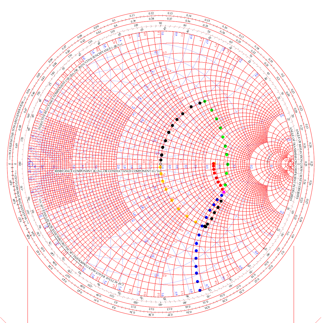
two color smith chart showing two possible ways to solve for L networks to match a transmitter to an antenna.
In the video above, he used the path of going up (like my green dots) and then following the 50 ohm arc back down (black dots from the green intersection point). But he was using a simple circuit built on a SMA connector. For an antenna installation though, it really makes more sense to me to actually follow the black line down from the start point and then follow the yellow line up the 50 ohm arc instead. Let me explain…
If we use the black arc that goes down first and the yellow one back to the center then what that looks like in the real world is a small capacitor from the base of the antenna to ground (this is what the black dotted line is after all). You see the black like is moving DOWN which means it will be a capacitor. We move it down till it meets the “50 ohm” circle so we can add the next part to move the point to the center of the chart. That next part isa series inductor between the base of the antenna and the coax. What us ham radio ops would call a load coil… This makes way more sense to me in this application than the other path which would be a “shunt” inductor or what would be an inductor from the antenna base to ground and then a series capacitor between the base and the coax. This is what would be similar to an L type antenna tuner to be honest but we are planning on using individual components in this lab… You see the yellow line is going UP to the central 50 ohm point, so this means it is an inductor and it is moving along the red lines on the chart which means it will be in series with the antenna.
This is actually really simple to be honest:
Red lines and your “movement” is going down - Series Capacitor
Red lines and your “movement” is going up - Series Inductor
Blue lines and your “movement” is going down - Shunt (Parallel) Capacitor
Blue lines and your “movement” is going up - Shunt (Parallel) Inductor
Do you see the pattern? Tracking up the lines on the chart is always inductors and tracking down on the lines is always capacitive. Like wise, if you use a blue line for your movement the the device will be in parallel and if the color of the line is red then it will be a series part. Now the color codes of my dotted lines above is purely there to make it easier to see what is happening and mean nothing other than that. The colors I am really concerned with are the two colors of the chart itself.
Math with a Smith Chart to match an Antenna
So the math is actually really simple to be honest. If you look at the first arc (the black line moving down) it is read on the blue chart (admittance - which is the opposite of resistance…) as it is moving along the blue circles. it is moving from about .19 to .48 on the blue chart (this is called suseptance, but you really don’t need to know that for this application) as you can see the lines run out to the perimeter where it is marked. This is .29 distance units on the admittance half of the chart. This .29 is the opposite of resistance so we then have to invert it (1 divided by .29), so it is a reactance value that we can use to do the math with, which turns it into 3.449 or as it should read -j3.449 (remember, because it is below the center line of the chart) and this is then multiplied by 50 (the value we assigned to the center point to start with) to get the actual reactance. 3.449 × 50 = 172.45 ohm of capacitive reactance. We now know everything in the formula to turn this into capacitance… since it is the same formula, you just switch out the two values. Super simple to be honest. Xc= 1/(2 x Pi x f x C) is turned into C=1/(2 x Pi x f x Xc) as you can see, we just plug in the numbers and then we get the capacitance. BTW, we are making this for 10 mhz so we can listen to WWV in Ft Collins… haha, why not?
Mathing this first step involved counting on the chart and subtracting the smaller number from the larger, then inverting it since it is on the blue lines (because the blue lines represent the opposite of resistance and we need it to be a resistance value), then multiplying that number by the center assigned value (in this example it is 50 ohms) and we ended up with 172.45 ohms of reactance. Now we turn this into C= 1/(2×3.1415×10e6×172.45) which is C=92.3pf
Once this step is done, we simply run up the red unity circle to the 50 ohm point in the middle and do the same thing but for inductance (since it is moving up on the chart). It looks like it is on about 1.42 on the red lines at the bottom of the chart, just take a look and see what I am talking about… Since it goes all the way up to the horizontal line, we just use this number and multiply it by the center value again (are you noticing a trend here yet?) and we get XL=1.42×50 so XL=71 ohms of reactance The we flip the inductive reactance formula and this time the formula looks a little different since it is XL=2 x Pi x f x L so to get inductance from inductive reactance the formula looks like this L=XL/(2 x Pi x f) so now we know all the numbers for this one too. It looks like this now L= 71/(2×3.1415×10e6) and this equals L=1.13uH of series inductance since this movement happened on the red lines and went UP.
So adding a 92.3pf shunt capacitor from the base of the antenna radiating element to ground (honestly an appropriately sized trimmer cap like a 50-100pf trimmer would be optimal since the calculated size is such an odd value...sure as a bird flies, this is some sort of common size…lol) Next is to insert a base “load” coil between the feedline and the antenna that is 1.13uH in size. This will match our mythical vertical to be resonant with the 10 mhz WWV signal as close to perfect as humans can get it. It SHOULD (if the parts are the right value) move the Smith chart plot to the center point on the chart which the goal for impedance matching.
Clear as mud again, right? HaHa… You can see it seems like a lot, but once you do it a couple of times, it really does get a lot easier to understand. I recommend you watch the video a couple of times and print off a chart from the web to practice on like this one.
Help support his website by using these Amazon Affiliate Links when you shop…

Ten watts to Spain. Ten watts to Germany. Ten watts to Austria. The EFHW at 35 feet made all the difference.
Activating Hillsborough River State Park (US-1878) with a friend is one thing—making over 100 contacts in a single afternoon using QRP power and a homemade wire antenna is another. That's exactly what Chas and I accomplished using a 65-foot EFHW antenna strung 35 feet up in the Florida pines, a ground mounted vertical, his FT891, a Penntek TR-35, and my sBitx v3 running just 10 watts (Chas was running 50 watts today though). This wasn't just a Parks on the Air activation—it was a field test of how well minimalist gear performs in a multi-operator setup, complete with lessons learned about antenna placement, front-end overload, and working around the Florida sun.
Activating Hillsborough River State Park (US-1878) with a friend is one thing, making over 100 contacts in a single afternoon using QRP power and a homemade wire antenna is another. That's exactly what Chas (NA2B) and I accomplished using a 65-foot EFHW antenna strung 35 feet up in the Florida pines, a ground mounted vertical, his FT891, a Penntek TR-35, and my sBitx v3 running just 10 watts (Chas was running 50 watts today though). This wasn't just a Parks on the Air activation, it was a field test of how well minimalist gear performs in a multi-operator setup, complete with lessons learned about antenna placement, front-end overload, and working around the Florida sun.
Hillsborough River State Park entrance designated K-1488 for Parks on the Air activations.
Hillsborough River State Park: Location and Access
Hillsborough River State Park sits about 12 miles north of Tampa and makes for an excellent POTA location. When you arrive at the entrance, the first thing you're greeted with is a ranger station where you pay your four dollar entrance fee. Yes, you read that right—four dollars for the whole day. This is a really nice park with extensive hiking trails, a large loop perfect for biking, and the Hillsborough River running through it where visitors can enjoy boating and fishing.
There's plenty of infrastructure here for families… playgrounds, picnic areas with covered pavilions, and well-maintained facilities. For POTA activators, the key feature is the abundance of tall trees throughout the park, making it ideal for wire antennas. The main loop road has several pull-off areas with picnic tables that work perfectly as operating positions. Cell phone coverage is good throughout the park, which helps for spotting yourself on the POTA network and coordinating with other operators.
After paying the entrance fee, I drove around the loop a couple of times while talking to Chas on the phone, trying to figure out where he'd set up. Here's the kicker, though, he decided to drive over to my location so we could operate together from adjacent tables. This gave us the multi-operator experience but also taught us some valuable lessons about antenna placement and RF interference, which I'll get into later.
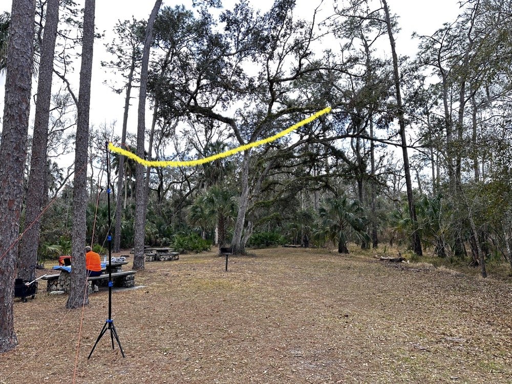
The 65-foot EFHW antenna strung into the tree canopy (highlighted in yellow) getting the wire 35 feet high made a dramatic difference in propagation. The wire itself is nearly invisible against the tree background.
The Antenna Setup: 65-Foot EFHW in the Trees
Today saw the use of a 65-foot long wire antenna, an End-Fed Half-Wave from Reliance Antennas. This antenna isn't rated for high power, so I held all of my transmit power to 10 watts or less throughout the day to prevent potential damage to the matching transformer. We deployed it using throw lines to get it about 35 feet up into a large oak tree, then Chas loaned me his 10-foot push-up pole and stand to support the feed point end of the antenna and get it a little higher off the ground as well.
I believe this additional height aided propagation dramatically. Getting the whole 40-meter EFHW that high off the ground, with the far end even higher in the tree, made a noticeable difference compared to previous activations where I'd run antennas lower. I made many contacts all over the United States, into Mexico, and even worked some European stations on the higher bands with just 10 watts. That's the magic of getting a wire antenna up high… height matters more than power in many cases.
The EFHW is resonant on 40m, 20m, 15m, and 10m without needing an antenna tuner, which keeps the station setup simple. I specifically avoided the WARC bands (30m, 17m, 12m) during this activation because the antenna isn't cut for those frequencies and I didn't want to deploy a tuner. Sometimes keeping things simple is the better approach, especially when you're testing equipment and learning how gear performs in the field.
The ranger station where you pay the $4 entrance fee to access the park for POTA activations.
Radio Gear: Penntek TR-35 and sBitx v3 Performance
Once I had the antenna set up and tested, I decided to use the Penntek TR-35 transceiver first. I really enjoy using this tiny little radio, the CW break-in is phenomenal, and the keying from the internal keyer circuit works flawlessly. It's a true QRP radio putting out 5 watts maximum, and I've made some additional accessories for it to turn it into a more complete field station. But even as it sits stock, it's a wonderful little radio that's almost impossible to damage from bad antennas or other field mishaps. Plus, it just works really well at making contacts.
I started on 40 meters and after working through a good run of stations, I decided to move up to 20 meters where activity was heating up. Chas started on 30 meters and worked his way through the WARC bands, eventually ending up on 10 meters where we made a park-to-park contact with each other from 30 feet apart. That was pretty funny, logging a P2P (park-to-park) contact when we could literally see each other across the operating area. I turned my output power all the way down, it showed literally zero output and I was still booming into Chas’ radio!!! Haha!
After finishing my run on 20 meters with the Penntek TR-35, I swapped it out for my sBitx v3. I throttled the output power on the sBitx for two reasons: first, to prevent damage to the antenna which isn't rated for high power, and second, to keep from running down my battery too quickly. I'd brought an 8 amp-hour LiFePO4 battery, and if I'd run the sBitx at full output power I could have easily depleted that battery in an hour or so, especially running FT8 on the lower bands which requires more transmit time. As it turned out, limiting power to 10 watts kept the battery happy all day and I still had plenty of capacity left when we packed up.
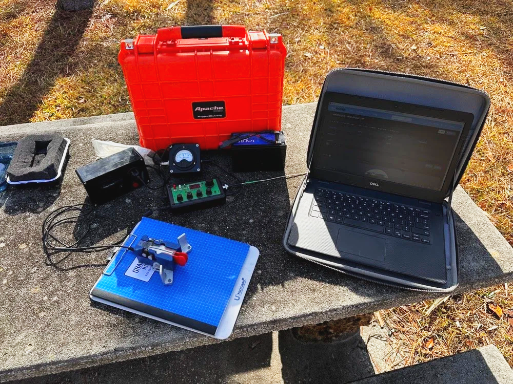
Initial station setup with the Penntek TR-35, Dell laptop for logging, clipboard with paper log, and CW paddle ready to make contacts.
The first thing I did with the sBitx was get on 15 m and attempt to make contacts there on FT8. This went pretty well and I made several contacts on 15 m before moving to 10 m to see what I could make on that band. The reason I skipped the WARC bands today was because this antenna is not resonant on any bands other than 40, 20, 15, and 10 m. So I stayed on those bands as I did not want to try and deploy an antenna tuner as well.

The sBitx v3 with improvised sunshade, Florida sun glare was a constant challenge throughout the activation. Notice the notebook to keep my arm off that rough concrete!
Contact Statistics:
Between Chas and me, we logged 118 total QSOs during the activation! 66 in my log and 52 in Chas's log(I did operate a little longer than him and we were not in a race either). Here's my detailed breakdown:
David's Stats (WK4DS):
40 meters: 5 QSOs (all CW)
20 meters: 50 QSOs (all CW)
15 meters: 1 QSO (CW)
10 meters: 10 QSOs (8 FT8, 2 CW)
Total: 66 QSOs
CW: 58 contacts
FT8: 8 contacts
Geographic Breakdown:
Domestic (USA): 56 QSOs across the continental United States
DX (International): 10 QSOs reaching six countries:
Spain: 2 contacts (EA4T, EA5BCO)
Germany: 2 contacts (DL4JCP, DJ9HX)
Mexico: 2 contacts (XE2BCS, XE2IF)
Austria: 1 contact (OE2IGP)
Canada: 1 contact (VE1ZZ)
Poland: 1 contact (SQ9JS)
Czech Republic: 1 contact (OL26WRTC - special event station)
NA2B Chas's Stats: Chas logged 52 QSOs throughout the day, primarily working 30m, 17m, and 10m (he might have done more but that is all I know of) while I focused on 40m, 20m, 15m & 10m. This band coordination helped us avoid stepping on each other while maximizing total contacts for the activation.
Combined Performance: For QRP power (my 10 watts maximum and Chas running 50 watts) and simple antennas, 118 total contacts in one afternoon represents excellent POTA performance. The 10 DX contacts on 10 meters with just 10 watts and the EFHW antenna particularly stand out, working Spain and Germany on FT8, then switching to CW for additional European contacts, demonstrates what's possible when propagation cooperates and you get your antenna up high.
Twenty meters was the workhorse band, delivering 50 contacts in my log alone. The concentration of activity on 20m CW (14.061 MHz) is typical for POTA activations, as this is where most hunters are listening for parks. The handful of 40m contacts at the start of the activation caught the tail end of daytime propagation before that band shifted to primarily short-skip domestic contacts.
Operating Challenges - Sun and Glare
Both Chas and I learned pretty quickly that the Florida sun was not our friend today, even though the temperature was pleasant. The glare from the sun continuously made us struggle to see our displays and adjust settings. I think Chas literally just toughed it out and lived with squinting at his screen. I, on the other hand, kept deploying improvised sunshades and repositioning my station to create shade for my equipment as the day wore on, as you can see in the photos. This is something to think about when planning a POTA activation, a simple popup canopy or umbrella can make the difference between comfortable operating and constantly fighting the sun. Add that to my growing list of field operation lessons learned.
sBitx v3 CW Keying: Improvements and Remaining Issues
The CW keying in the sBitx has been dramatically improved as the software revisions continue. The developers keep optimizing the scan time of the Raspberry Pi processor and how the program executes, making the keyer more responsive with each update. It's almost like using a regular radio now, though there are still quirks you need to work around.
I've learned that I have to pay very close attention to my sending cadence when working CW with the sBitx. The keyer isn't as forgiving as a traditional Curtis-style keyer circuit, and it will send errors if you're not careful with your timing. Knowing this limitation, I work much harder to stay at one speed setting throughout a contact when possible. It's easier to develop muscle memory and consistent sending rhythm at one speed rather than constantly adjusting the keyer speed up and down as I might do with other radios.
With a traditional Curtis keyer, minor variations in your paddle timing get smoothed out by the keyer circuitry and everything sends cleanly. The sBitx will occasionally miss characters if you vary your speed too much, if you slow down suddenly, you can actually outrun the radio's keyer circuit and it won't register that you asked for a "dit," so it leaves it out. This isn't a deal breaker, but it does mean the sBitx requires more disciplined sending technique than most modern transceivers.
I do tend to make more mistakes with the sBitx than I do with other more traditional Morse code radios, and I think all of this traces back to the timing limitations from the Raspberry Pi's scan cycle. But it's getting better with each software update, and for a radio that does CW, SSB, and all digital modes in a package this small and affordable, I'm willing to work around the keyer quirks.
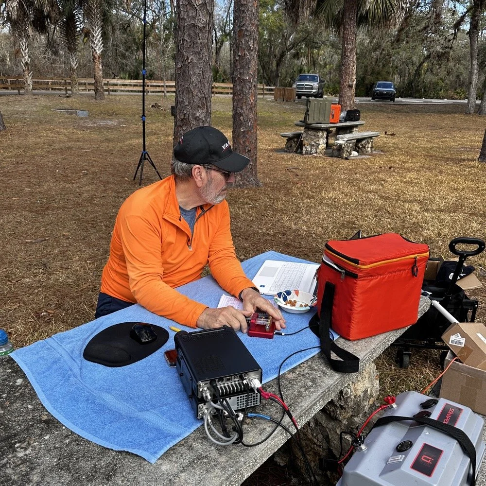
Chas operating his Yaesu rig from the adjacent picnic table. His vertical antenna is behind me and to my right. My wire antenna is behind him.
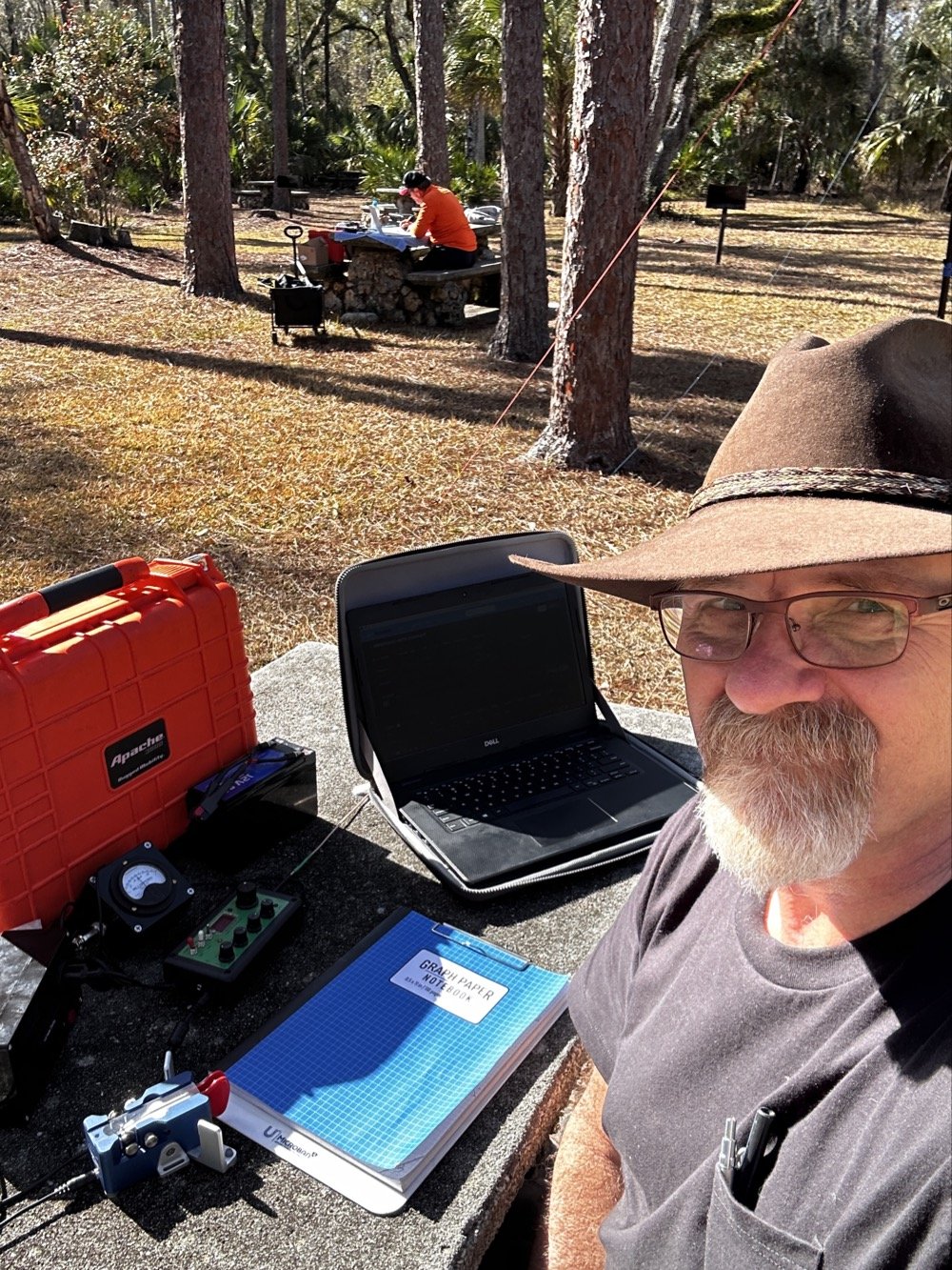
My operating position in the foreground with Chas visible about 30 feet away in the background—close enough for a park-to-park contact but creating some RF interference challenges.
20-Meter Band Issues: IRF520 vs IRF510 Amplifier Problems and Receiver Front End Overload"
The final two photos show a couple issues I've been wrestling with on my sBitx. The first image shows my sBitx operating on 10 meters with lots of noise lines visible in the waterfall display. These noise lines are coming from Chas transmitting Morse code on a different band, his signal is getting into my receiver and creating visible interference. I don't remember exactly what band he was on, but the important lesson here is that antenna placement matters tremendously when you're running multi-station setups like this one.
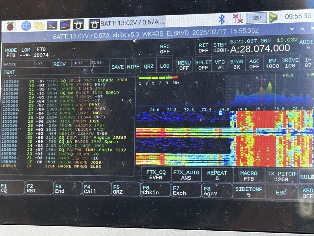
sBitx running FT8 on 10 meters (28.074 MHz) showing the noise spikes from Chas transmitting on a different band nearby 9in the waterfall) this is what front-end overload looks like in a multi-op field setup. The vertical lines in the waterfall are RF bleed-through from his station 30 feet away.
Be mindful of where you place antennas if you're operating a multi-operator event. We were only 30 feet apart, which is far too close for optimal isolation. I was still able to work many contacts even with this persistent noise coming through, though. This is something you learn to work around if you're going to be an amateur radio operator in a multi-operator event of any kind…think Field Day here. It's just part of the game, so you expect it and adapt. We could have used bandpass filters to eliminate most of this interference, but I didn't bring mine to the park.
The next photo shows my sBitx on 20 meters, and on 20 meters my radio has a persistent issue that I'm still troubleshooting. I'm beginning to believe it has to do with the IRF520 MOSFET transistors that I used in the power amplifier section when I built this radio. These IRF520 transistors have significantly more internal capacitance than the IRF510 transistors that Farhan originally specified in the revised amplifier design. I think this extra capacitance is causing the amplifier to oscillate, and that oscillation is what you're seeing as the noise signal in the photo.

sBitx on 20 meters CW mode (14.061 MHz) showing the noise from what I am suspecting is from oscillating mosfets.
Here's the interesting part: as the radio warms up during operation, this spurious noise signal moves down in frequency within the 20-meter band. If I want to push it out of the way temporarily, I'll switch to 40 meters or 80 meters and run FT8 for a few minutes. You generate more output power on those lower bands, which heats up the amplifier section faster. Usually, if I just run FT8 first thing when setting up, it warms up the transmitter enough to push the oscillation down to below where I normally work CW on 20 meters anyway, giving me a temporary workaround.
This isn't a permanent solution, obviously. I'm convinced I'm going to have to address this capacitance issue when I get back home, probably by swapping out the IRF520s for the specified IRF510s or adding additional filtering to the amplifier circuit. But for now, knowing the workaround lets me keep the sBitx operational in the field for POTA activations, which is what matters most.
Multi-Operator Challenges: RF Interference and Antenna Placement
Operating two stations in close proximity taught us several valuable lessons about multi-operator setups. The biggest challenge was RF interference between our stations. With antennas only 30 feet apart, we experienced significant front-end overload, when Chas was transmitting on his station, I could see his signal bleeding through into my receiver on completely different bands.
The sBitx has a somewhat easy-to-overload front end compared to more expensive commercial receivers, which made this problem more pronounced. But even with a better radio, operating this close together without bandpass filters or careful band coordination is asking for trouble. The solution for future multi-op activations is simple: either space antennas much farther apart (100+ feet minimum if possible), or operate on bands that are far enough apart in frequency that filter roll-off provides natural isolation.
The position of your antennas matters just as much as the distance between them. If we'd oriented our antennas at right angles to each other instead of parallel, we might have achieved better isolation through pattern nulls. These are the kinds of things you learn by doing, and they apply equally to Field Day operations where you might have multiple stations running simultaneously.
Despite the interference challenges, we still made excellent contact numbers. Multi-operator POTA activations are worthwhile because you can cover more bands simultaneously, operate different modes at the same time, and keep the activation going continuously while one operator takes a break. Just be prepared to work around the RF challenges that come with the territory.
Who Should Activate This Park?
Hillsborough River State Park is an excellent choice for both first-time and experienced POTA activators. Here's why:
For beginners: The $4 entrance fee is minimal, facilities are excellent with clean restrooms and covered picnic areas, and the tree coverage makes wire antenna deployment easy. You don't need to hike to reach good operating locations…everything is accessible by car right off the main loop road.
For experienced activators: The park's location north of Tampa puts you in a good spot for both domestic and DX contacts. The tall pines support wire antennas at significant heights, and there's plenty of space to spread out if you're running a multi-operator activation.
Best practices for K-1488:
Arrive early morning (8-10 AM) or late afternoon (3-5 PM) to avoid midday heat and sun glare
Bring sunshade or canopy, there's limited natural shade at the picnic tables
Plan for 2-3 hours of operating to get a good contact count
Cell coverage is good for self-spotting on the POTA network
Spring and fall offer the best weather conditions
If you're in the Tampa Bay area and looking for an easy, productive POTA park with good facilities, Hillsborough River State Park should be on your list.
Activating Hillsborough River State Park proved to be a highly productive POTA outing. Between Chas and me, we logged well over 100 contacts using QRP power and simple wire antennas…proof that you don't need high power or expensive gear to have success in Parks on the Air. The 65-foot EFHW at 35 feet worked exceptionally well, the Penntek TR-35 remains one of my favorite field radios for CW, and the sBitx v3 continues to impress despite some remaining amplifier quirks on 20 meters.
Key lessons learned: antenna height matters more than output power, multi-operator setups require thoughtful antenna placement to avoid interference, and limiting transmit power to 10 watts keeps your batteries happy all day. If you're looking for a beginner-friendly POTA park in Florida with good tree support and easy access, Hillsborough River State Park (K-1488) is an excellent choice.
Have you activated K-1488 or other Florida state parks? Share your experiences in the comments below, I'd love to hear about your favorite POTA locations and antenna setups.
Want more POTA activation reports and technical amateur radio content? Check out my other WK4DS blog posts for detailed equipment reviews, antenna builds, and field operation tips.
Frequently Asked Questions About POTA Activations
What is Parks on the Air (POTA)?
Parks on the Air is an amateur radio operating activity where hams set up portable stations in state and national parks to make contacts. Activators (operators in parks) try to make at least 10 contacts to qualify the activation, while hunters (operators at home) try to contact as many parks as possible. It's similar to Field Day but focused on public parks and conservation areas. POTA encourages hams to get outdoors, test portable equipment, and promote amateur radio to park visitors. The program started in 2016 and has grown to include thousands of parks across the United States and internationally.
How do you activate Hillsborough River State Park for POTA?
To activate Hillsborough River State Park (K-1488), you need to set up your amateur radio station within the park boundaries and make at least 10 contacts. Pay the $4 entrance fee at the ranger station when you arrive, then find a suitable operating location with trees for antenna support. Most activators set up at picnic tables near the main loop. Operate from battery power or a generator, no AC mains allowed for POTA activations. Log your contacts using a smartphone app like HAMRS or POTA Logger, then upload your log to the POTA website within a few days. The park has excellent tree coverage for wire antennas and is open from 8 AM to sundown year-round.
What is an EFHW antenna and why use it for POTA?
An End-Fed Half-Wave (EFHW) antenna is a wire antenna that's fed at one end through a matching transformer (typically a 49:1 unun), making it incredibly easy to deploy in the field. For POTA activations, EFHWs are popular because they require no ground radials, work on multiple bands without a tuner if cut for harmonically-related bands, and can be thrown into trees using a throw line and weight. My 65-foot EFHW works on 40m, 20m, 15m, and 10m, covering the most productive POTA bands. Getting it 35 feet high significantly improved propagation compared to running the same antenna closer to the ground. A properly deployed EFHW antenna at height will often outperform a vertical antenna at ground level for DX contacts.
Can you run two stations at the same POTA activation?
Yes! Running multiple operators at the same park location is allowed and encouraged in POTA. Each operator logs their own contacts and submits their own activation log. Chas and I each operated our own stations about 30 feet apart, which let us cover different bands simultaneously and maximize the total contact count. However, you need to be mindful of RF interference between stations. With our antennas so close together, I experienced front-end overload on my sBitx when Chas was transmitting on nearby bands. Solutions include better antenna separation (100+ feet apart if possible), using bandpass filters on receivers, or coordinating to operate on widely separated bands like 40m and 10m simultaneously.
What's the best QRP radio for POTA activations?
For CW-only POTA activations, the Penntek TR-35 is exceptional. It's lightweight (under a pound), battery-efficient, has outstanding CW break-in, and is nearly indestructible, perfect for field operations. For multi-mode operation covering CW, SSB, and digital modes, the sBitx v3 offers incredible value and capability in a portable package, though the CW keying requires careful technique and practice. Other popular POTA QRP rigs include the Elecraft KX2/KX3 (premium price but premium performance and battery efficiency), QRP Labs QCX-mini (CW-only, ultra-portable and inexpensive), and the Xiegu G90 (good SSB performance, acceptable CW, built-in tuner). Choose based on your preferred modes, budget, and how much weight you want to carry into the field.
How many contacts should you expect from a POTA activation?
Contact numbers vary widely based on propagation conditions, time of day, your operating skill, and whether you're spotted on the POTA network. A successful activation requires at least 10 contacts to count, but most activations yield 20-40 QSOs in an hour or two of operating. Our 100+ contacts in one afternoon between two operators was excellent, partly because we covered multiple bands and modes (CW, FT8) and had good propagation to Europe on the higher bands. If you're new to POTA, expect 15-30 contacts on your first few activations. Using CW typically yields more contacts than SSB due to pile-ups from hunters chasing parks, and FT8 can be productive when propagation is marginal or when SSB isn't getting through.
My 66 contacts plus Chas's 52 gave us 118 total QSOs from K-1488 on February 17, 2026. Ten of mine reached six countries across two continents, all at 10 watts or less.
You can help support this channel by using these Amazon Affiliate Links as well:
QRP/Portable Radios:
Antennas & Tuning:
CW Equipment:
Power & Accessories:
Organization & Transport:
BONUS ITEMS
73
David / WK4DS
Overall, today we had a wonderful day and made many contacts and was able to test antennas and enjoy ourselves in the warm Florida sun far from home where all the cold weather and dreariness is at. So until next time, get your radio out and go power it up and make a contact on it. That’s why you bought it after all.
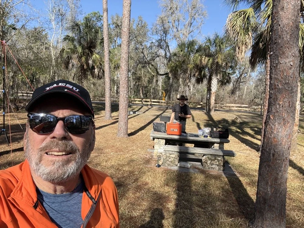
Chas grabbing a photo from his perspective for posterity! HaHa! Look at all that stuff I brought!
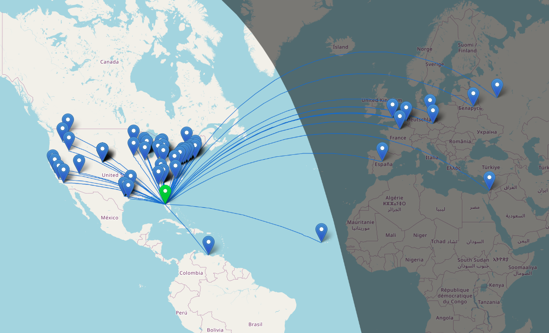
Over 100 QSOs at Chito Branch US-5524 POTA Activation AAR
Once on 15 meters with a warm radio, I set off with calling CQ on a clear frequency. I called for maybe two or three minutes before I started getting replies…and then I got more, and more, and more till I had a genuine pileup on 15 meters! There was times when I am sure I could hear at least ten stations calling at once and this happened a coupe of times today!
Today saw me working on my kilo at Chito Branch again. I figured I would net 30, maybe 40, contacts considering the band conditions and the problems I was running into, but nothing prepared me for what happened today…
The Antenna and Radio Setup
I arrived at the park after hitting a pretty heavy traffic jam this morning a little frustrated since I am attempting to secure the kilo before we leave town for the rest of the year. I get to the park and there is not a single person on site other than me, which gives me the pick of the litter of locations. I immediately go about setting up the antenna and tuning it.
I also noticed today something about the antenna that was of interest to me. I will be investigating it further and writing about it soon. It is that the characteristic impedance of the vertical can not be made purely 50 ohms without a reactive component at all. It simply doesnt work. I testing it for a few minutes as I was curious and as I would tinker with the vertical and the radials to move the plot to purely resistive, it would move the frequency of the antenna off at the same time (stands to reason) but I couldn’t get it to a nice clean 50 ohms no matter what I did. I tinkered with it and the radials till I got the null on frequency and the SWR as low as feasible and moved on to the radio.
After I finished setting up the antenna, I chose to use the TenTec Scout 555 amateur radio and only pulled the 15 and 20 meter band modules for today’s activity. I wanted QSOs in the log and not exotic bands today… I had made a mistake last night though, this radio is temperature sensitive to some degree, it will drift in frequency (mine wanders slowly up) till it warms up from use. So when I am running the keyer and the radio is in transmit a lot calling CQ, the radio heats up in the back and slowly that heat creeps forward in the case to warm the rest of the electronics. Once warm I find the radio to be very stable and work exceeding well, but until it does, I have to watch it and turn the VFO down a little at a time till it is warm. This is what I had to deal with today
The POTA Activation Begins…
People were sending me notes in the spots on the POTA website about my frequency so I would know about the drift. I love how the hunters are there for you all the time, even once they have you in the log. That is awesome camaraderie if I must say so. I racked up a staggering 35 QSOs in short order! It was going so well that I figured I would hop onto 15 meters and see if I could get 40 or 45 before I ran out of time… What happened next blew my mind. After I worked those 35 stations it is like the radio simply turned off, I don’t know if I had worked everyone on the band or if the band had started to close, but I could no longer hear anyone calling. So I called CQ a couple more times and finally after not hearing anyone else for a coupe of cycles, decided to QSY to 15 meters.
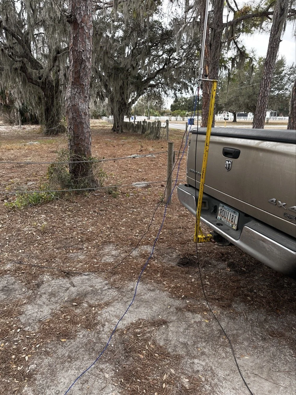
The ¼ wave telescoping vertical antenna was simple and effective today.
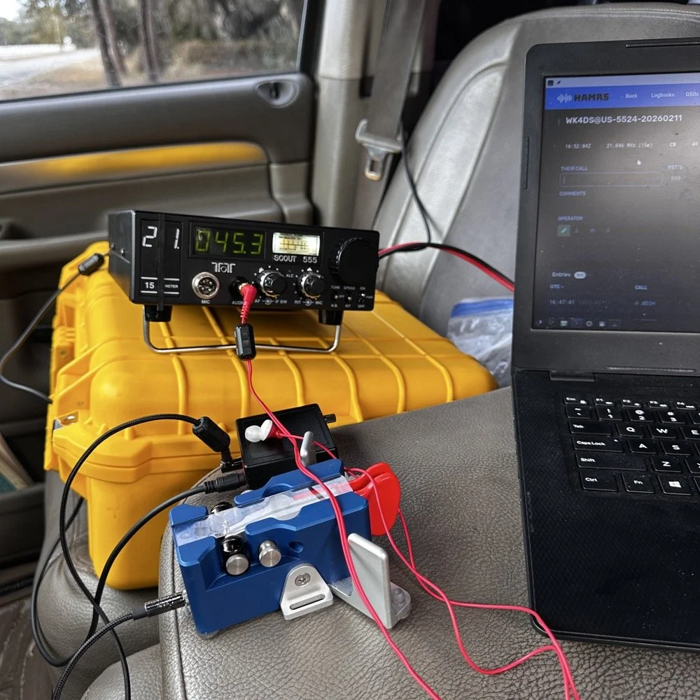
TenTec Scout 555 Amateur Transceiver with Begali Travler CW Key
15 Meters Gets Sporty!
Once on 15 meters with a warm radio, I set off with calling CQ on a clear frequency. I called for maybe two or three minutes before I started getting replies…and then I got more, and more, and more till I had a genuine pileup on 15 meters! There was times when I am sure I could hear at least ten stations calling at once and this happened a coupe of times today! I also knew from prior experience that 15 meter is kinda where I start really hearing DX stations when the band is in good shape so I was kinda listening for stations with callsigns that start with letters other than A,K,N and W. I have found that after doing POTA for a while that my brain instinctively listens for one of those letters first in the call. If I don’t hear one of those 4 at the beginning then something in my brain trips and I only get the last 2 or 3 letters of the callsign and require a repeat…unless…I am on 15 meters and above.
It is really rare for me to even hear DX with the antennas I use for POTA until I get up to 21 mhz or higher. To be honest, I am surprised I hear them at all with some of the antenna designs I use. The ¼ wave vertical pictured above is a prime example, I am pretty sure this antenna needs to be a good bit higher in the air for a good DX take off angle, but here we are….
Here is the list of the DX I worked today from a POTA park:
DX Countries Worked:
Working DX on simple antennas is one of the joys of amateur radio. The ARRL's guide to HF propagation explains why 15 meters can be so productive for European contacts from the US.
Venezuela - YV1GIY
England - G0LLU, G3NKQ
France - F6CAX, F6OYU
Spain - EA4MZ
Belgium - ON5JT, ON4ZD
Czech Republic - OK1MGW, OK1XC
Germany - DF2PI
Cape Verde - D4HP
Belarus - EW6GB
Russia - R1QBD/3
Israel - 4Z4DX
China - SH2NR
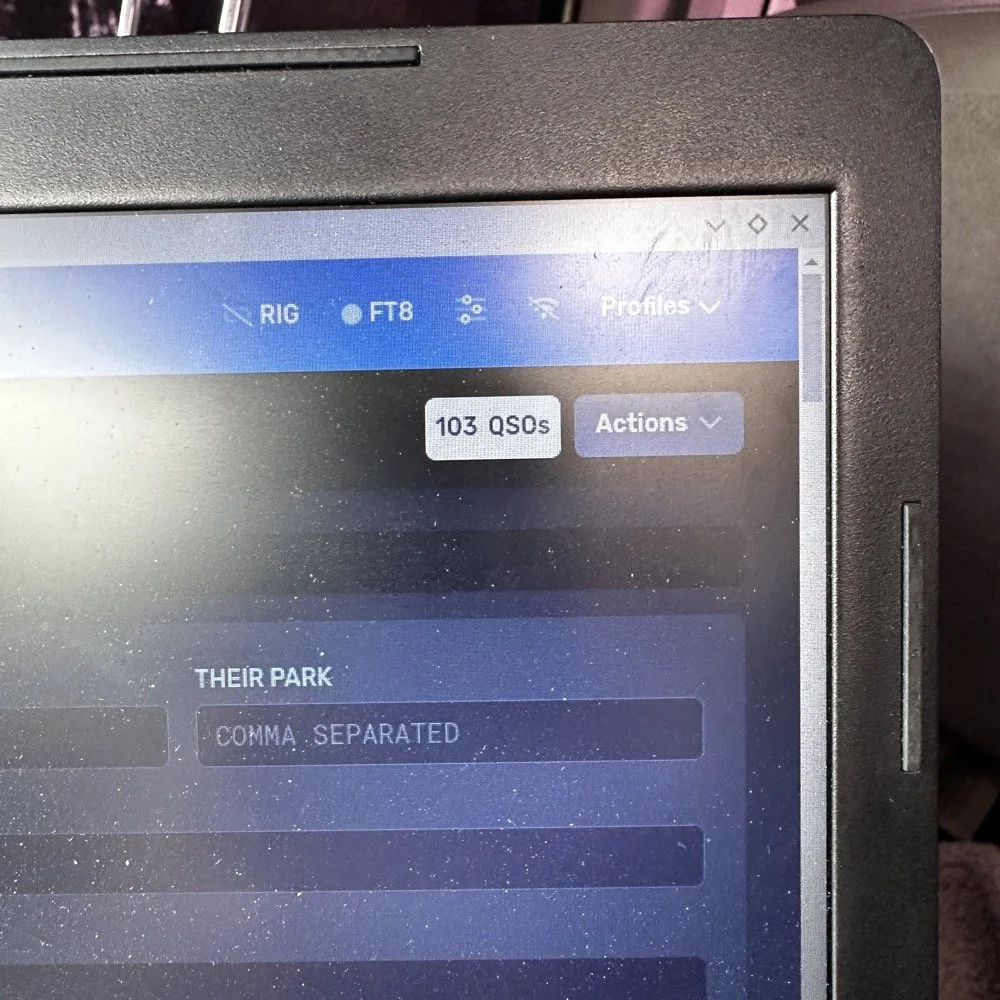
I use HAMRS for my POTA logging.
AAR POTA Wrap Up
As you can see, I was hearing people from all over the world! I couldn’t believe some of the ones on this list. I don’t think I have ever worked Cape Verde before! He was really weak too, I could just make out the call and signal report after him repeating it a few times, but we got it done! Europe would come booming in with spurts of band openings apparently as I would work two or three at one time then it would go silent in the EU for a while then it would happen again.
Now this is not to say the band was in perfect condition. There was considerable QSB (fading) of the signals today, but it was manageable with a decent set of headphones and a properly adjusted radio. I could hear all but maybe 3 stations that I could hear at all. Of those three, one of them I almost got but then it faded out completely. I was so close too… Anyway, the calls just kept coming in and over the next hour I hit 50 then 60 then 70 and the log just kept building. I use HAMRS for my POTA logging and it shows the total in the top corner like a little scoreboard...
I finally got to something like 78 and had a couple of duplicate calls by now so I wanted to finish with a solid 80 and started really working towards this new little goal I had thrown up. Then I did it and then ran right past 80 to almost 90! It just kept happening! 15 meters was on fire today! I finally got to about 98 and I was almost out of time so I decided to stop at 100 even if I didn’t account for the duplicates. 98 is better than being late for picking up the XYL (the wife)… haha. But then I hit a little run of 5 and landed finally on 103 and the goal being reached, I called QRT and powered off the station. This is what I love about POTA, the callers were coming in from everywhere.!

Screen capture from the HAMRS logging software QSO map.
This map blows my mind, all of those calls were worked on a 30 year old, 40 watt TenTec Scout 555 radio (I turned the power down from factory spec for a reason)that has to warm up to stay on frequency, with an “outdated” mode that appears to be very NOT outdated at all, with a less than ideal antenna! So with all this I have to say, just get something together and don’t worry too much about if it has perfect SWR or if the antenna is “high enough” for DX, obviously that don’t matter when the band conditions get right! Now of note, most of the DX (I think almost all of it other than Venezuela, is 15 meters only) also all of the west coast if 15 meters as well as several of the ones due north of my position.
Elated at the fact that I had put over 100 calls in the log toward my kilo, I hurriedly broke down the antenna and packed the radio away and drove off to get the wife from school. Now if I can just repeat this again tomorrow…haha.
How many watts does the Ten-Tec Scout 555 output? The Ten-Tec Scout 555 outputs 50 watts from the factory, I have mine “turned down” to 40 watts as this is a simple adjustment and helps protect the radio from high SWR issues in the field, which is more than adequate for POTA activations and working DX on CW. Despite being a 30-year-old radio, it performed exceptionally well during this activation and many others in the past.
What bands work best for DX during POTA activations? 15 meters (21 MHz) and above typically offer the best DX opportunities during POTA activations (for me at least). At US-5524, nearly all European DX was worked on 15 meters, while 20 meters provided primarily US contacts.
Do you need a perfect antenna for POTA DX contacts? No - this activation proved that DX is possible with simple antennas. Using a basic quarter-wave vertical with radials at ground level, I worked 12 countries across Europe, South America, Africa, and Asia…in one sitting.
Why does the Ten-Tec Scout 555 drift in frequency? The Scout 555 is temperature-sensitive and drifts slightly as it warms up during transmit cycles. Once warm (after 15-20 minutes of operation), it becomes very stable. Simply adjust the VFO slightly downward as it warms. The radio drifts in frequency due to component value changes as they warm up, this is common in older equipment or less sophisticated designs like the Scout 555. Things like crystals will change frequency when they get warm, other things like capacitors will also change value with temperature if they are not specifically stabilized versus temperature.
What is the best logging software for POTA activations? HAMRS is excellent for POTA logging - it's free, works offline, handles POTA references automatically, and generates helpful QSO maps. It also exports to ADIF format for easy upload to pota.app. Is it the best? For me it is…
Related Posts
Hope you enjoyed this AAR, leave a comment and I look forward to hearing from you in a future one,
You can help support this website by using these Amazon Affiliate Links:
QRP/Portable Radios:
Antennas & Tuning:
CW Equipment:
Power & Accessories:
Organization & Transport:
BONUS ITEMS
David - WK4DS
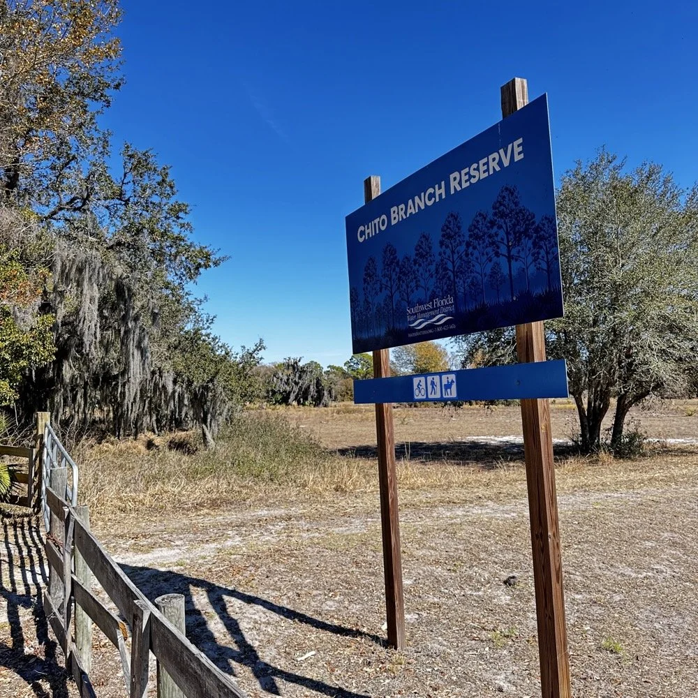
Chito Branch Reserve: First FT4 Contacts, Meeting a Fellow Park Hunter, and the Quest for 1000
Doug's been activating Chito Branch quite a bit lately, and if I'm being honest, we seem to be in a friendly race to see who hits 1000 contacts from this park first. Spoiler alert: he's winning. But it was great to finally shake hands with someone who understands the appeal of spending beautiful Florida mornings in a park with Spanish moss hanging from the trees, headphones on, working the world.
February 10, 2026 • US-5524
Sometimes the best part of a POTA activation isn't the DX you work or the pile-ups you run! it's meeting another operator face-to-face who's been chasing the same goals you have. Today at Chito Branch Reserve, I finally got to meet Doug, KQ4SXW, in person.
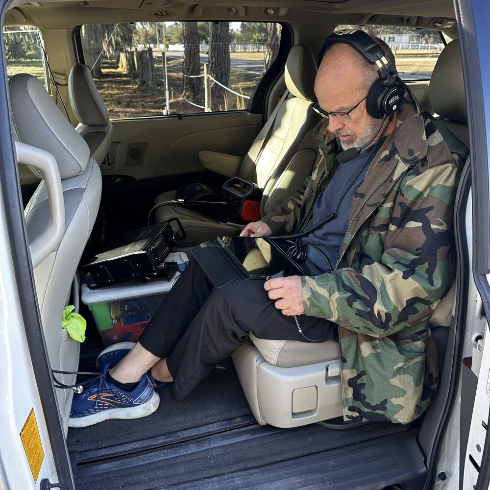
I finally got to meet Doug, KQ4SXW
Doug's been activating Chito Branch quite a bit lately, and if I'm being honest, we seem to be in a friendly race to see who hits 1000 contacts from this park first (well, between us at least). Spoiler alert: he's winning. But it was great to finally shake hands with someone who understands the appeal of spending beautiful Florida mornings in a park with Spanish moss hanging from the trees, headphones on, working the world.
The Setup
I rolled into Chito Branch mid-morning with my usual portable arsenal. The park is close to where I'm staying in Tampa, which makes it an easy choice for activations, and I've been systematically building toward that 1000-contact milestone. As of today, I'm sitting at 769 QSOs logged from US-5524, so I'm getting close.
For antennas, I ran my 1/4-wave vertical with two counterpoise wires, tuned for each band. Simple, effective, and quick to deploy. I use the nanoVNA to utne the antenna with. As you can see in the plot above, I get it to something less than 1.5:1 SWR and call it good, I have found that if I get it to that level that I dont have any trouble making contacts at all. I have done OK with the SWR higher in the past…much higher actually, but it is a lot tougher to make contacts like that.
The main rig was the sBitx V3 from HF Signals for digital modes, and I brought along the Ten-Tec Scout 555 for some 15-meter CW work since the bands were looking promising.
Speaking of which… let me tell you about my grid square insurance policy.
A Sticky-Note Solution to a Real Problem
If you operate FT8 or FT4, you know that your grid square locator needs to be correct. It matters for awards, for logging accuracy, and frankly, for not looking like you don't know what you're doing. Recently, I completed an entire activation with the wrong grid square set in the software.
Not ideal.
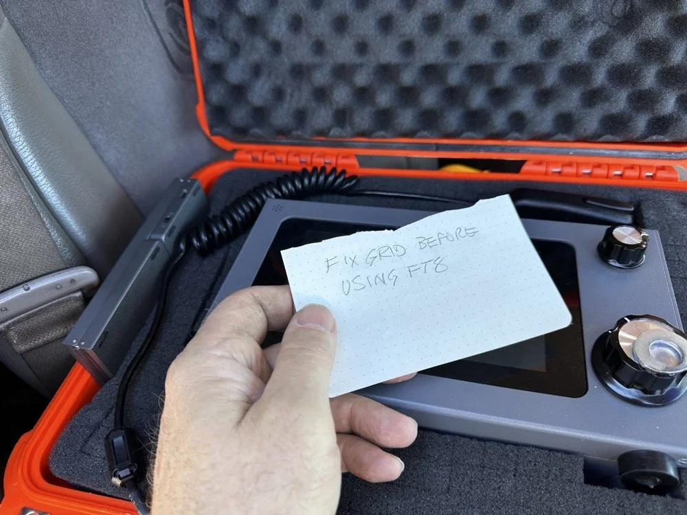
Sometimes the best solutions require the simplest answers…
So I came up with a foolproof solution: I now keep a note in my radio case that says "FIX GRID BEFORE USING FT8." It sits right on top of the sBitx when I open the case, impossible to miss. I also store the Bluetooth keyboard in the case with the radio so I can easily update the grid square in the field without fumbling around with the tiny on-screen controls.
Is it a high-tech solution? No. Does it work? Absolutely. Sometimes the best fixes are the simplest ones.
Starting with FT8 on 20 Meters
After getting the sBitx fired up…with the correct grid square, thank you very much… I started the activation with FT8 on 20 meters. I spotted myself on POTA and the responses started rolling in. There's something satisfying about watching those waterfalls fill up with decodes and seeing callsigns appear in the queue.
My very 1st FT4 QSO with the sBitx!
I worked through a solid session and logged about 18 contacts on 20-meter FT8. The band was cooperative, signals were good, and the activation was off to a strong start. Something to note about my sBitx V3 is that it has developed a sort of internal noise on 20 meters that lingers in the CW portion of the band. It goes down in frequency as the radio warms up so I have to figure out what is causing this problem when I get home the next time. I have it on the list right next to fixing my microphone pre-amp circuit for proper operation as well.
First FT4 Contacts at a POTA Park
After the FT8 run, I decided to try something new: FT4. I've run plenty of FT8 from parks, but FT4 was uncharted territory for me in the field.
FT4 is faster than FT8, cycling every 7.5 seconds instead of 15, which makes it great for contesting or when you just want to move quickly through a pile-up. I updated my spot on POTA again and started calling CQ. To be honest, I had used it a little in the shack before with no luck so I didn’t hold my breath today, To me utter surprise, I saw a QSO forming in the call feed on the left! Then it finished and logged it! I hurriedly got out my phone and snapped a quick photo to share with you guys…
First contact: AA5WH on 20 meters. Clean decode, solid signal, contact in the log. Then I switched to 15 meters and worked N1KLF. Two FT4 contacts, my first ever from a park, and honestly? I was pretty stoked. There's something satisfying about trying a new mode and having it just work.
15 Meters CW Was Alive
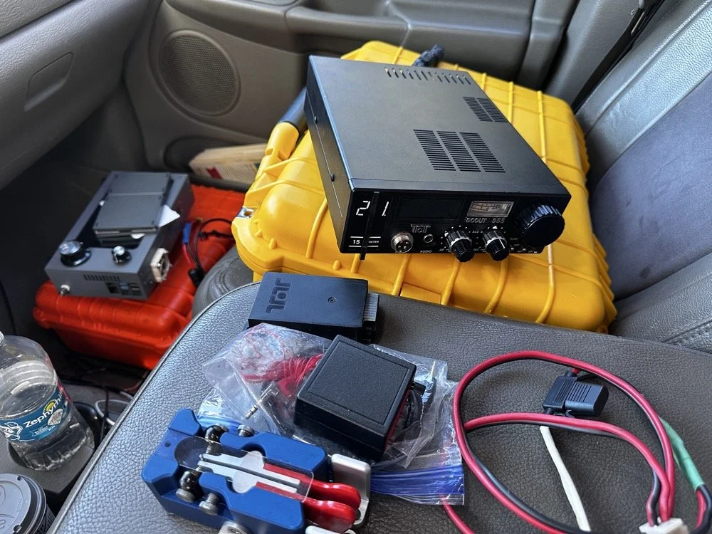
The TenTec Scout 55 is pictured with the HF Signals sBitx V3 where I was changing over to CW after working 2 digital modes today.
After the FT4 session, I switched gears completely. I packed up the sBitx and pulled out the Ten-Tec Scout 555 for some CW on 15 meters. The band was in great shape, though there was a bit of QSB rolling through. I got the radio all connected up to the keyer and then plugged in the Travler. My Begali Traveler key has become one of my favorites—smooth action, compact enough for portable ops, and it just feels good. It is sensitive, but that is how I use my keys, I prefer a light action myself and that is why I made my own paddles back in the day. N3ZN (Tony) and I2RTF(Pietro) make some of the nicest keys around at the moment and I am glad I have one from each.
DX Contacts That Made It Worthwhile
Right out of the gate, I snagged some DX that made the whole activation worthwhile:
EA4MZ in Spain
DD1LD in Germany
YV1GIY in Venezuela
PY5XT in Brazil
Four different countries, all on 15-meter CW with 40 watts and a telescoping 1/4 wave vertical, what more can you ask for? Days like this remind me why I love this hobby. Some of them were a little on the weak side but the Jones filter in the Scout actually helps if you open it up instead of closing it down. This seems counter intuitive, but opening the filter up just ever so slightly will let a lot more of the other operators signal though and just a little of the background noise, it is almost like having them turn their power up 50% or something, if you have not tried it with your Scout 555, I suggest you find a signal you can barely hear and give it a shot.
43 QSOs and Counting
By the time I packed up, I had 44 contacts in the log, though one turned out to be a duplicate, so 43 that counted. Not a huge number, but solid for a few hours of casual operating across three modes (FT8, FT4, and CW) and two bands.
Meeting Doug in person was the cherry on top. It's always good to connect with like-minded people in the hobby, especially when you're both chasing the same quirky goals. A thousand contacts from one park? Yeah, it's a bit obsessive. But things like that are what makes it fun.
SIDE QUEST TIME:
I ran into a unique problem today that is worth mentioning here. I was charging my computer with an inverter that I have wired into the cab of my truck. I was also running the truck so I could power the inverter and charge the computer as well as the sBitx V3 at the time. Well it turn out that I have some issues with this inverter that need resolving. The next few photos show the RF hash that this inverter is producing when under load! It is unreal how bad it was, I couldn’t believe all I had to do was simply shut off the engine and unplug the power cord from the logging computer and it went completely away…
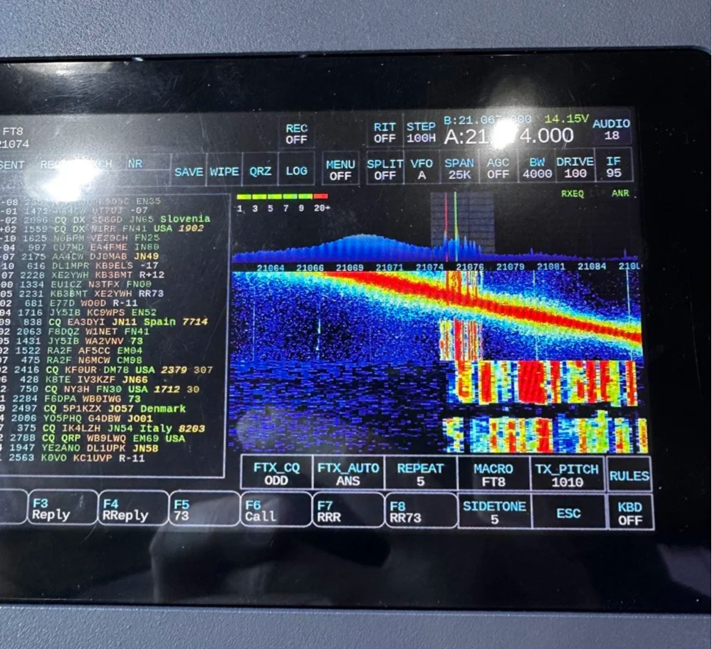
The above photo shows the hash of running both devices on the inverter with the engine running on the truck.
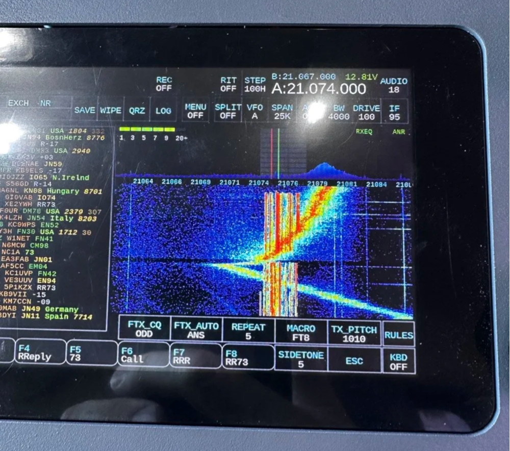
The next photo shows what happened when I shut off the truck and unplugged the computer.
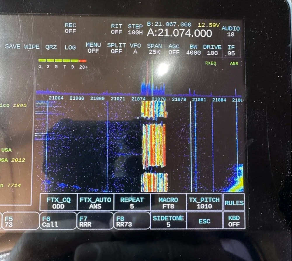
The last photo shows what the band looked like once I went around to the other side of the truck and powered off the inverter completely. This goes to show that you need to check these things if you plan to use RF devices like radios in the presence of RF trash generating devices like this inverter… Better inverter coming up!
END SIDE QUEST
Hit me up!
231 contacts to go until I hit the big 1000 from Chito Branch. At this rate, it'll take a few more activations, but I'm not in a hurry. Well, maybe a little… Doug's still ahead of me.
If you're in the Tampa area and see someone set up at Chito Branch Reserve with a vertical antenna and a tablet running digital modes, stop by and say hello. Chances are it's either me or Doug, and either way, you'll be in good company.
**Gear Used This Activation:**
- **Radios:** HF Signals sBitx V3, Ten-Tec Scout 555
- **Antenna:** 1/4-wave vertical with dual counterpoise wires
- **Key:** Begali Traveler
- **Digital Mode Software:** JJ and the sBitx 64 bit Development team version 5.301 (FT8/FT4)
- **Computer:** Dell Inspiron with Linux and HAMRS
- **Accessories:** NanoVNA for antenna tuning
Have you tried FT4 for POTA activations? What's your go-to mode for portable operations? Drop a comment below or find me on Facebook or shoot me an email on here.
What is FT4 and how is it different from FT8? FT4 is a digital mode similar to FT8 but with a faster cycle time (7.5 seconds vs 15 seconds), making it better suited for contests and quick pile-ups.
What equipment do I need for POTA FT4 activations? You need an HF transceiver capable of digital modes, a computer or tablet running WSJT-X software, an interface between your radio and computer, and a suitable antenna for your chosen bands.
Where is Chito Branch Reserve located? Chito Branch Reserve (US-5524) is located in the Tampa Bay area of Florida and is part of the Southwest Florida Water Management District.
How many contacts do you need for a valid POTA activation? You need a minimum of 10 QSOs to qualify for a valid POTA activation.
You can help support this website by using these Amazon Affiliate Links:
QRP/Portable Radios:
Antennas & Tuning:
CW Equipment:
Power & Accessories:
Organization & Transport:
BONUS ITEMS
73,
David WK4DS
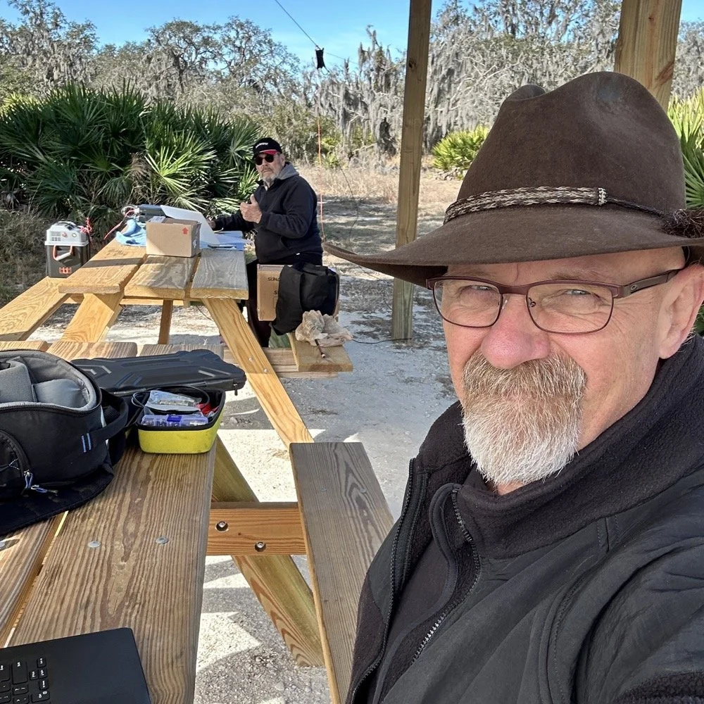
Joint POTA Activation with NA2B at Moody Branch: 104 CW Contacts in 4 Hours
Today I went to a POTA park to meet up with Chas NA2B, another amateur radio operator that lives just down the road from Chito Branch nature Reserve where I have been spending a lot of time here lately. He saw I was at the park on the spot page and simply hopped in the car and drove over for an eyeball QSO and to see if I wanted to meet up with him at some point and setup for an activation.
Today I had the pleasure of meeting Chas NA2B for our first joint POTA activation at Moody Branch Wildlife Management Area (US-6317) in Florida. What started as a chance encounter on the POTA spot page turned into a memorable 4-hour operating session that netted 104 total CW contacts between our two stations.
Today I went to a POTA park to meet up with Chas NA2B, another amateur radio operator that lives just down the road from Chito Branch nature Reserve where I have been spending a lot of time here lately. He saw I was at the park on the spot page and simply hopped in the car and drove over for an eyeball QSO and to see if I wanted to meet up with him at some point and setup for an activation.
This blog post will be an amalgamation of both discussing the activation as well as my new friend.
Planning the Activation
We communicated a good bit over the past week via text to line up a good day, (turns out every day is a good day for Chas…haha) and chose Tuesday as I had some business to attend to on Wednesday and the weather was way warmer than the previous day. The weather actually turned out to be about perfect to be honest about it. We agreed on Moody Branch US-6317 and 9:30 as the start time. We had planned to operate till about 2 if things were going good so on the day of, I load up the truck and head out. It takes about an hour to get there from where i was staying so I stopped and grabbed coffee and snacks along the way. Who doesn’t want a caffeinated CW op on the other end of their QSO???
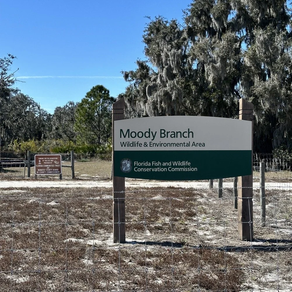
When I get there I am greeted with the standard issue Florida DNR signage and to my amazement there is a pavilion for us to operate from! Now to be fair, Chas had told me about it and the proximity to the parking lot. You see it was literally 15 feet from my truck to the table. Having the table this close allowed for an incredible amount of gear to be brought out. HaHa
Chas had already arrived and was setting up in the back of the pavilion so that I could have the closer spot and access to some really good trees to hang my antenna in. I decided to setup the antenna “properly” by putting the antenna tuner at the antenna instead of at the radio. This should provide better radiation than using the tuner to match the feedline as part of the antenna system. I simply set the case on the ground and set the tuner on top of it and tied the antenna wire to the case itself. The distance was about 50 feet from the table so I had to couple both of my longest coax cables together just to reach the tuner out by the tree.
The Setup: Remote Antenna Tuner Configuration
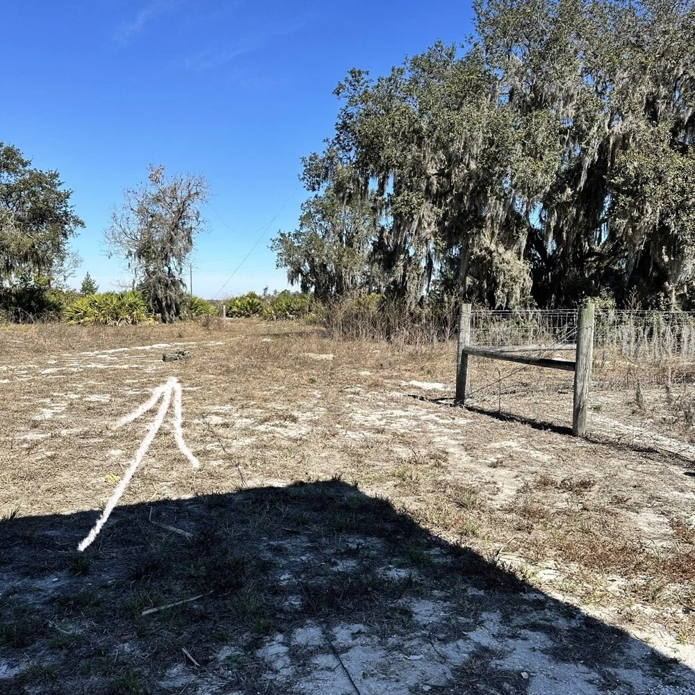
I put the antenna tuner way out here on purpose. The remote tuner setup keeps the feedline from becoming part of the radiator. This is important at it creates a more efficient antenna overall.
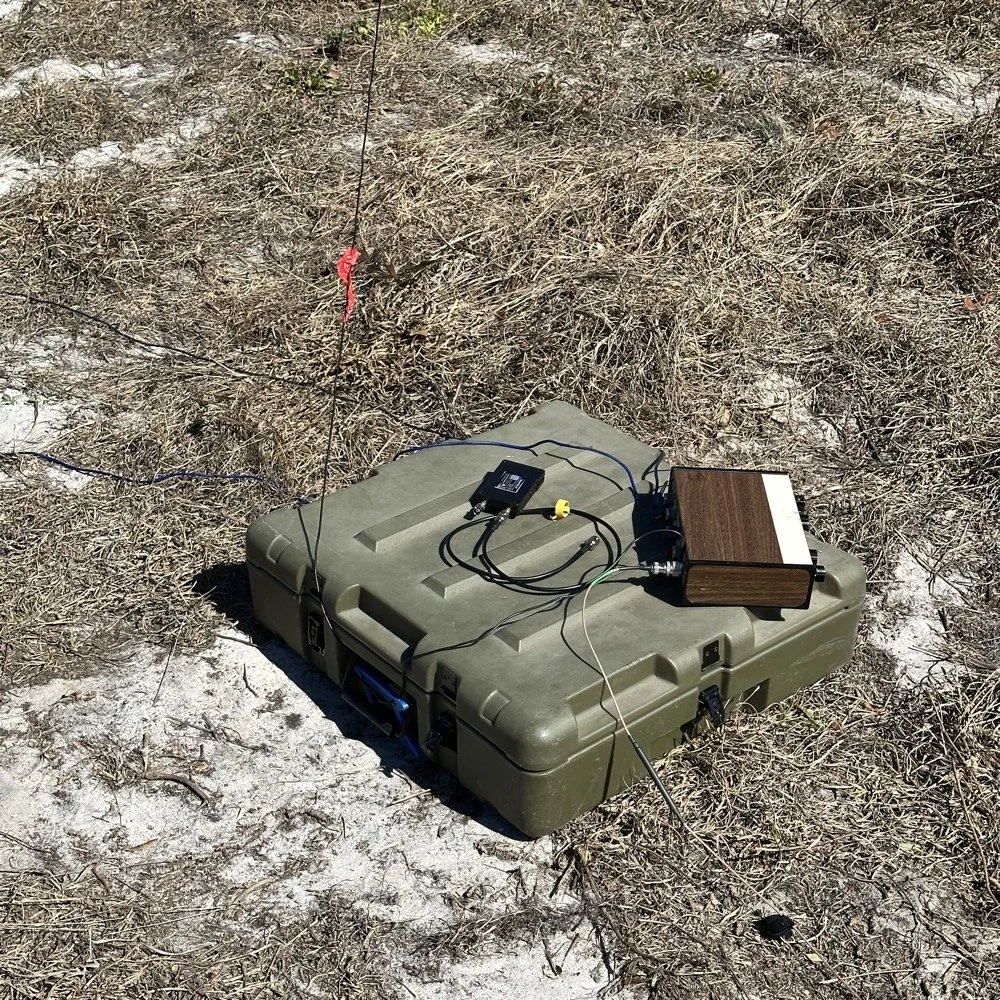
Since it was so far from the table, I just left the nanoVNA with the tuner so it would be nearby when I wanted to make band changes, of which there was many!
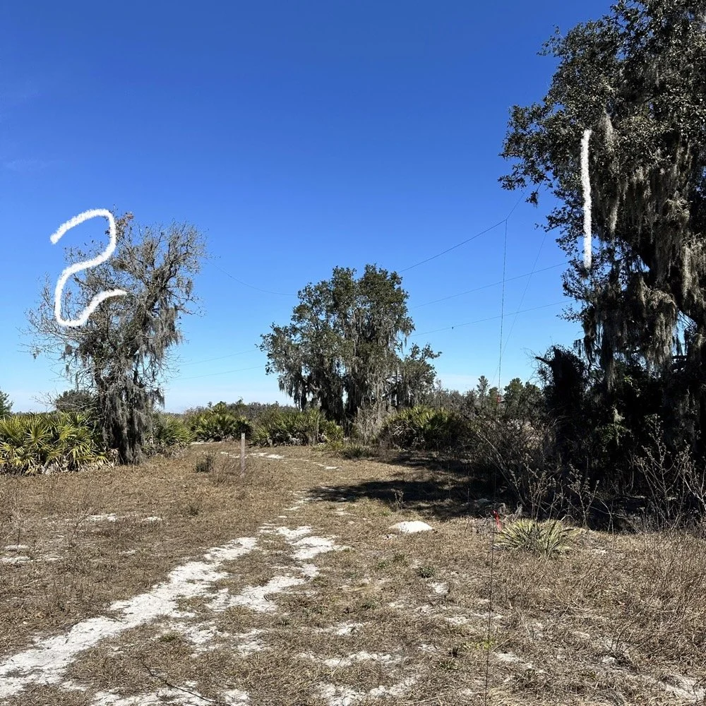
I strung the wire up like an inverted L type from tree 1 to tree 2 and tuned it for 40 meters to start with. Today I chose to start there as I was wanting to make contacts on all the bands I could with the Penntek TR-35 QRP radio. I also decided at the outset that I would work bands other than 20 meters today to see what I could come up with. I usually seem to have great luck with all the bands…other than 60 meters so far… haha. I also chose to run 10 watts or less all day too…well except for 40 meters, I ran 40 watts on 40 meters and still only made one FT8 contact there… lol. The band was just too noisy for me to hear anyone.
Equipment: QRP vs. Comfort
I only ran 10 watts or less the rest of the day because I didn’t have my large battery with me that I bring to power the sBitx at full power. I only had my 8 Ah battery and I didn’t want to deplete it early. I also had the 3Ah battery for the TR-35 and used it with that radio, but those were the power sources I was constrained to. This made me have to work a little harder for contacts, but it also made it a lot more fun to get DX stations in the log! I got at least 2 European stations in the log so I know it doesn’t take a ton of power to do it.
WK4DS (left) and NA2B (right) running simultaneous CW pileups on different bands at Moody Branch
Once setup I used two radios, the Penntek TR-35 QRP rig and the HF Signals sBitx V3. Both of these radios are cool in their own respect. I like the sBitx because I can run FT8 without needing to also connect a computer to the radio. The sBitx will internally log the contacts too so I could theoretically do an activation then when I get back home, down load the contact list and reformat it in ADIF and send it to the POTA site. That is kinda cool. The Penntek TR-35 is small, light weight and has a great receiver in it as well as awesome filtering. This little radio has everything you need and nothing you dont.
Above is me and Chas running pile ups on two different bands at once! We were both running CW today and at times I struggled to hear as my side tone and his were the same. I solved this by adjusting the side tone up a little so then mine and his were different ever so slightly and I could hear mine easily again. I think Chas stayed on 20 meters the whole time today. He racked up 61 contacts with the simple wire antenna. What a day in the field!
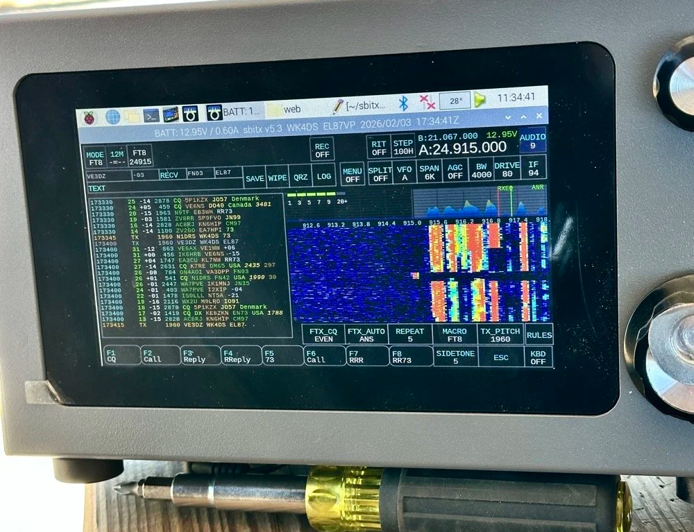
sBitx V3 running FT8 with new color-coded software from the open-source development team
This is what you see with the latest software release from the open source team on Github. This software has been made VERY good by this team of dedicated people and if you want to use this software yourself, just follow this link to JJ’s github page to learn more.
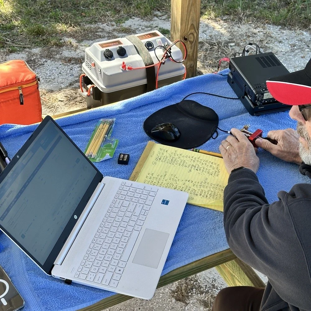
NA2B's minimalist CW station: paper logging, pencils, and a clean operating position
Chas had a really clean operating position today. He had plain pencils, which will ALWAYS work, a pencil sharpener and notebook for log data. He was in a blissful state. I also like the battery pack he has too. If I had brought my 36 Ah battery, I would have brought the Scout 555 out and ran it as well. Maybe forgetting it was a sign that I needed to let that radio rest a little…haha. His station looks so clean though, I was impressed.
My station on the other hand looked like I set off a “ham-grenade” lol… I had the logging computer, the foldable keyboard for the sBitx and the whole Penntek station was just piled in the orange storage case. Along with all that, I also had all sorts of other stuff that isn’t in this photo scattered around the table… It was kinda crazy how much crap I brought out.
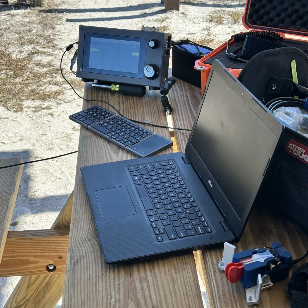
Operating Highlights
Chas setup his camera and grabbed this photo of us below for the blog. I like how his station has one box on the table and mine is covered in stuff! HAHA!
I will be honest, it was a lot of fun just hanging out while doing the activation. I do so many of these by myself that I forget that I can have someone with me while I do this.
We didn’t get in a hurry, we just took our time and whatever calls got in the log is what we got. There were a couple of time we both had decent pileups to work through, him more so than me as he had more power and 20 meters typically has more operators on the band. It wasn’t about QSO count…till it was… but all day we just made contacts and played radio.
Right before we finished for the day, I asked Chas how many contacts he had. Chas had 60 calls in the log and I had 38. I told him that we needed to have an even 100 calls between us before we stopped for the day. This total number of QSOs was completely arbitrary, but a cool little milestone none the less so we pushed on for a little longer. We finished the day with 104 total calls in the logs. Win! Chas had 61 as a final count and I ended up with 43! What a day!
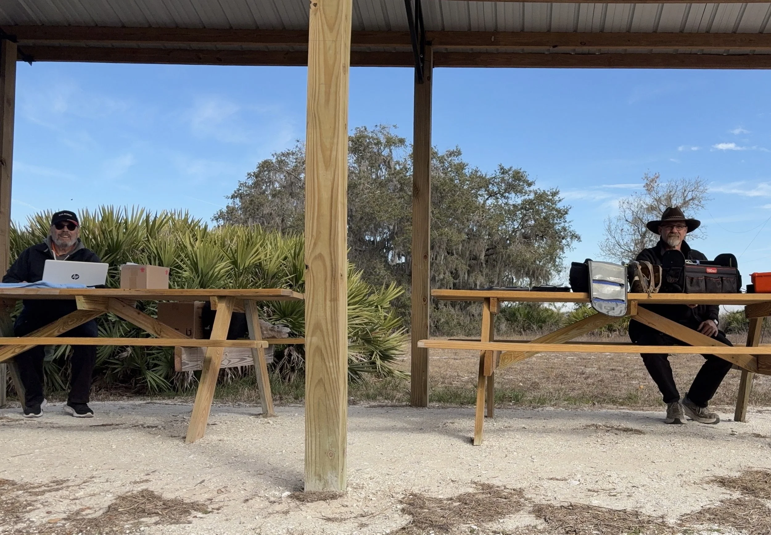
Multi-operator POTA setup at the pavilion - note the contrast in station complexity!
After about 4 or 5 hours of fun and games, we decided to break down and head back to our wives to get some lunch. It was a great day and I am glad I made a new friend as well.
Activation Summary:
- Park: Moody Branch WMA (US-6317)
- Operators: WK4DS & NA2B
- Total Contacts: 104 (43 WK4DS + 61 NA2B)
- Mode: Primarily CW, some FT8
- Bands: 40m, 30m, 20m, 17m, 15m
- Radios: Penntek TR-35 (QRP), HF Signals sBitx V3, Yeasu FT-891
- Power: 10 watts or less (QRP), 40w on 40m, 50 watts on 20m
- Antenna: Inverted L wire antenna with remote tuner, (Chas ran a random wire)
- Duration: 4-5 hours
You can help support this website by using these Amazon Affiliate Links:
QRP/Portable Radios:
Antennas & Tuning:
CW Equipment:
Power & Accessories:
Organization & Transport:
BONUS ITEMS
73
WK4DS - David
![Ten-Tec Scout 555 60m Band Module: IF Filter Redesign & Final Testing [Part 4]](https://images.squarespace-cdn.com/content/v1/5d17806ce65eba00011667cb/083bf6b4-e926-4837-8a07-9c333538b44c/IMG_1543.png)
Ten-Tec Scout 555 60m Band Module: IF Filter Redesign & Final Testing [Part 4]
Today saw me finish the TenTec Scout 555 60 meter Band Module Project in the workshop, now it is on to phase 2, testing in the field… I had wanted to rework the filter in the IF stage as it was not great from before. I was able to get a signal out of the radio, but the filter shape left something to be desired…
This is the final episode in my Ten-Tec Scout 555 60-meter band module series:
- Part 1: Initial Conversion and Filter Design
- Part 2: Crystal Selection and Mixer Circuits
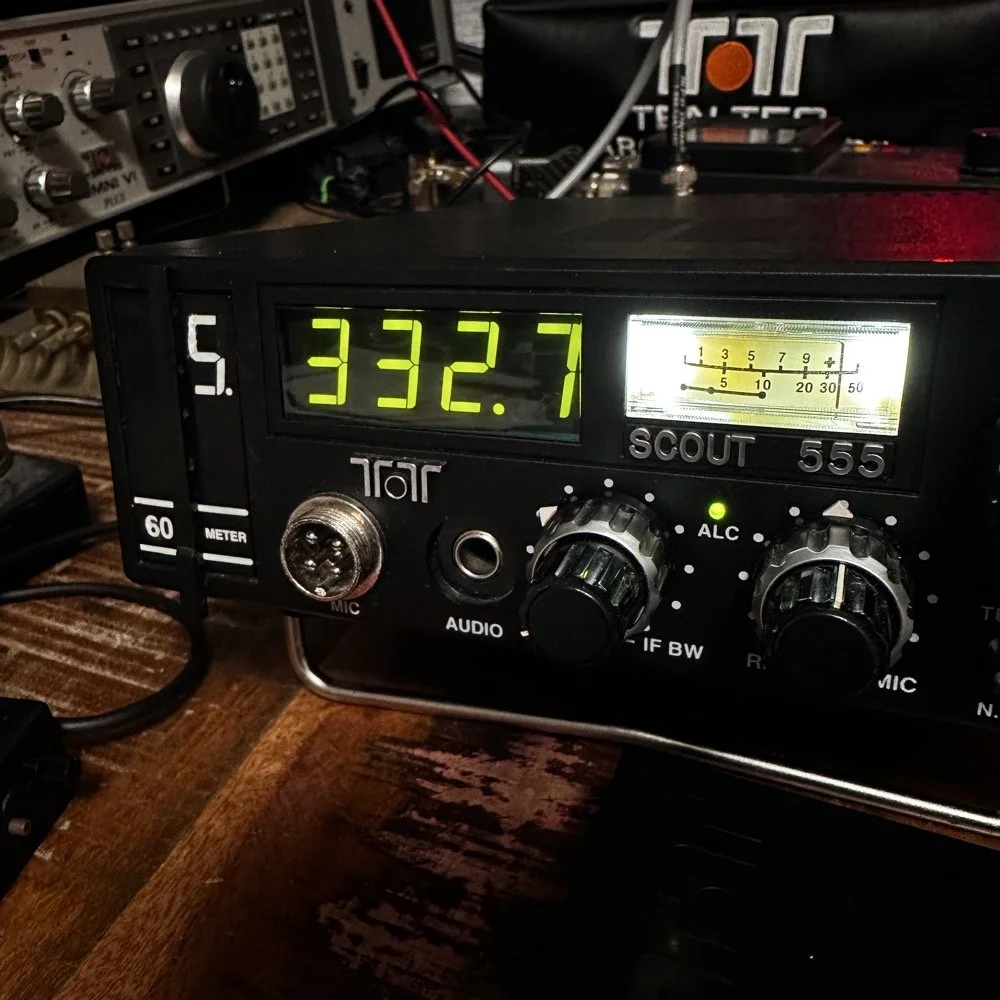
Today saw me finish the TenTec Scout 555 60 meter Band Module Project in the workshop, now it is on to phase 2, testing in the field… I had wanted to rework the filter in the IF stage as it was not great from before. I was able to get a signal out of the radio, but the filter shape left something to be desired…
The first chart image is of my filter after I got the radio to work. This is not what a bandpass filter should look like. The lower photo is of a factory TenTec VERY narrow bandwidth 40 meter bandpass filter. Turns out, this is almost impossible to replicate with discrete components that are not adjustable…as you will see. They used two tunable inductors to achieve this filter shape. I almost went to the trouble of adding some trimmer capacitors to mine, but as you will soon see, I felt it wasn’t needed. I soon learned what a filter Q is and why it matters when your trying to build a filter. I used some online calculators to get the component sizes for the filters and after messing around with a couple, I found one of the calculators had came up with numbers that were actually able to be made in my shop.
Armed with this information I decide to breadboard this filter first so I could tinker with it before soldering it to the band module circuit board. This, as it turns out, is a terrible idea if you plan to simply transfer the parts to the board and solder it all together. There is SO much stray capacitance and inductance at RF frequencies with a breadboard that you can build up a circuit, but when it comes to making the final item on perf board or Manhattan style, that you WILL use different values.
Looks good doesn’t it? Well look at the plot below! It actually looked great! It did have some insertion loss that I was not super happy about, but that plot looks great! Yes, the one inductor is hand made, I didn’t have one small enough in my little kits to work here I so wound one for the job. Notice how long the leads are on those components, that will come into play very soon…
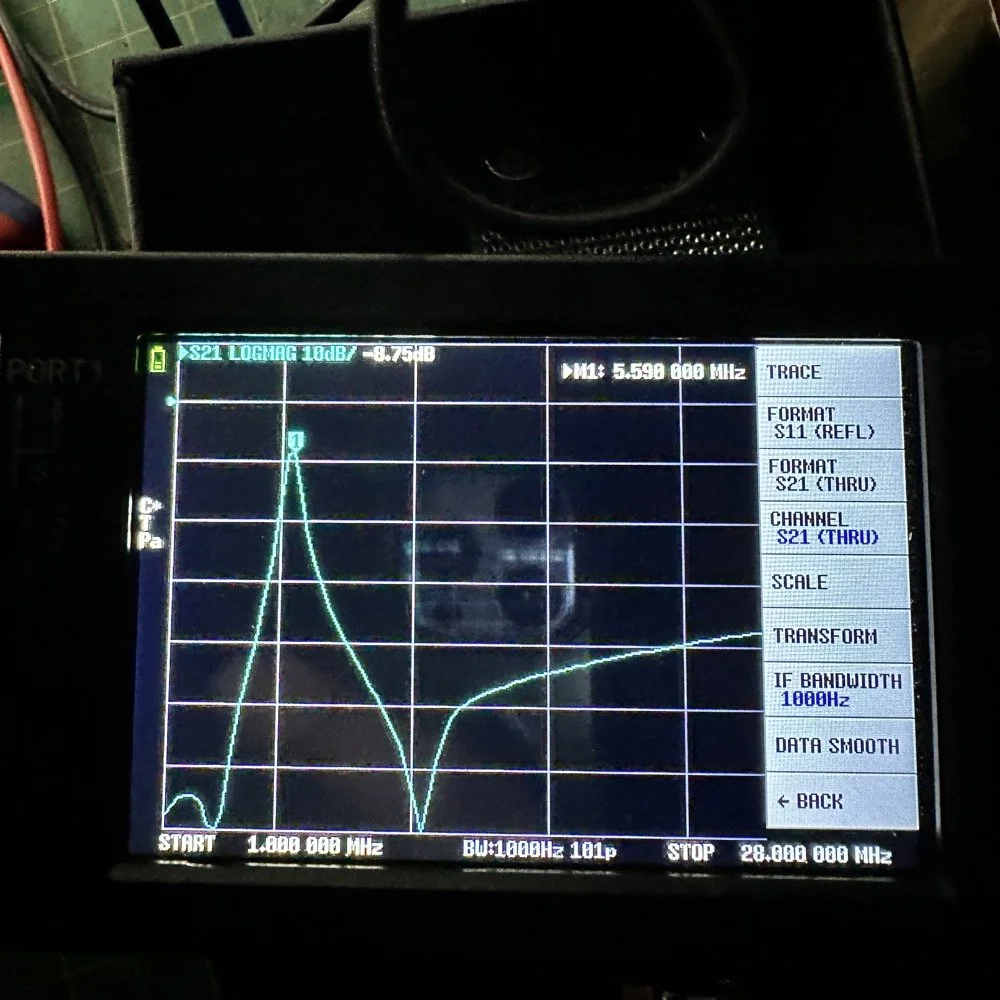
I may have gotten a little aggressive with the passband width… I think it was set to 200khz or maybe 500khz, but it was not much. I think the values I put into the online calculator were 5.4mhz center frequency, 500khz bandwidth and 3 LC stages in a “T” configuration. The bottom line on the chart is -70dB which is unbelievable! This thing was incredible! So I get the 60 meter module out and take it apart and strip out the old filter I had previously built wholesale leaving a clean slate for the new filter…
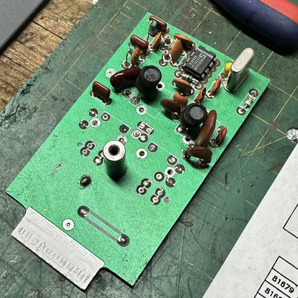
After I had the old filter gone and cleaned up a little, I cut me a pad as the new filter layout and the TenTec layout are different so I wanted to not have to permanently alter the circuit board other then removing the old components. This pad became the central connection point for the three stages. A little hot glue and I was in business! I simply tinned the whole top of the pad so I could land part leads where ever I wanted on it. This worked really well…much better than the filter I am about to build as it would turn out.
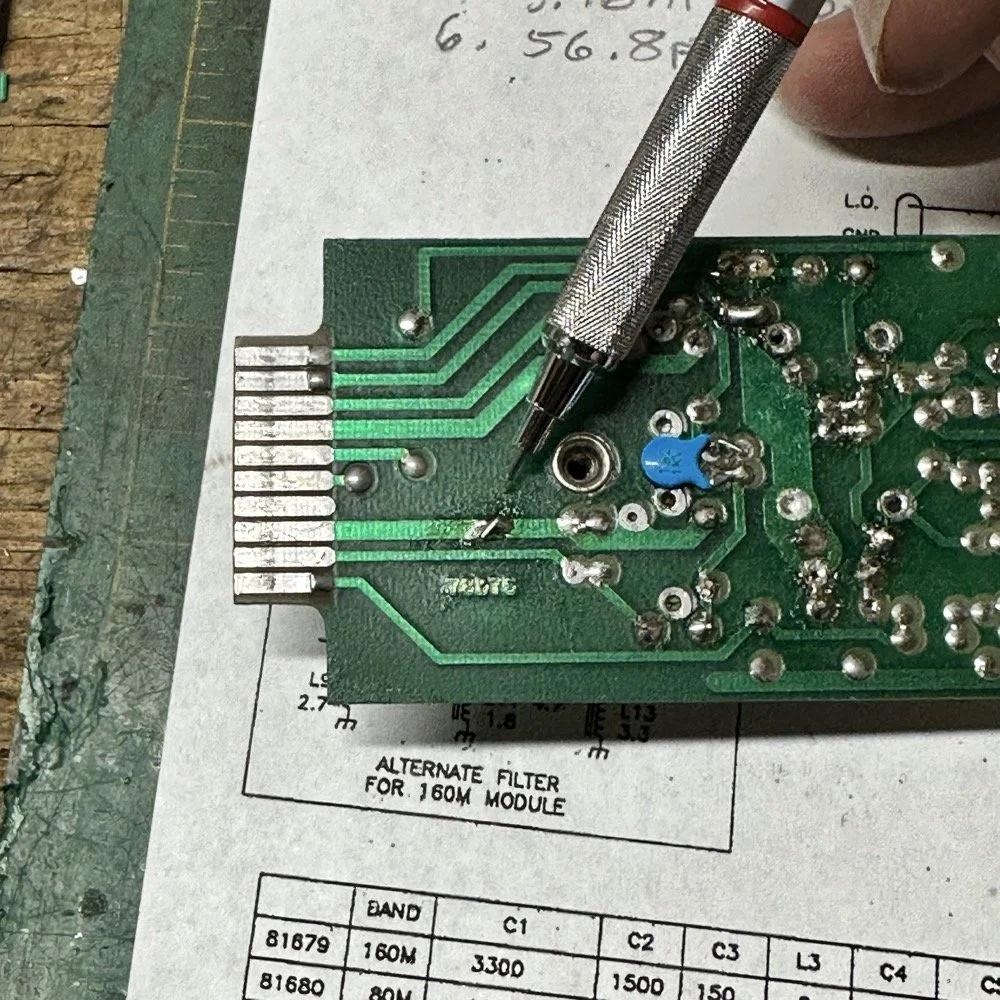
SIDE NOTE ABOUT MODIFYING SCOUT BAND MODULES:
What I am pointing out in these two photos is a home made Via that I added. You see, when you remove the canned tunable inductors from the board, turns out you break the grounds. TenTec decided that since these things were going to be here anyway, might as well use them for something. So they apparently decided to make them connect one ground plane to another in a couple of places on the board. Once you remove the cans, you lose a critical ground path…or two. I took a finger drill and a very small drill bit and drilled a hole from one trace to the ground plane on the opposite side(I am confident these are only two layer boards), then I soldered a bonding jumper wire in the hole so both planes would once again be connected again and all the stuff would continue to work properly. You also get to see the old homebrew filter in the below photo as a bonus.
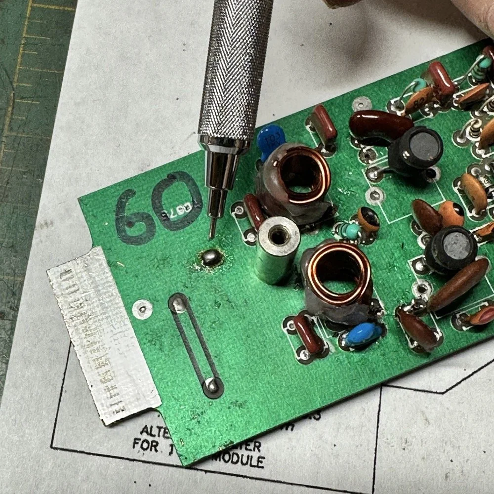
Below is the result of me simply attempting to move the parts over to the circuit board and soldering them in place… What a mess. I started with the exact parts you saw on the breadboard, but when I connected the nanoVNA to the filter I found the center frequency had moved up 500khz! It was now pushing my desired frequency out of the passband!!! I was seeing something like 16dB of loss at the desired frequency.
This is the world of ultra high Q passband filters made with inductors and capacitors I guess. Once I removed all the stray capacitance from the breadboarded system, all the capacitor values went down enough to make the filter not usable. That is why you see the mess below, I didn’t have room for the trimmer caps I have on hand so it was good ole trial and error method instead to get the passband in the right spot. To be fair, this mess actually worked, it just had something like 12 or 13dB of insertion loss in the filter which made the output power go way down. I used the amp meter to check it and the current draw on transmit with this filter was 1.8 amps and the current draw with the factory 40 meter band module was 9.3 amps. So I took a break and grabbed some food and went back to the drawing board…
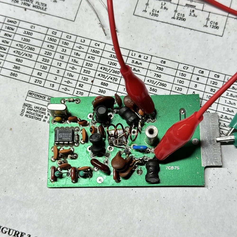
I am going to admit something here that might make some people unhappy with me…I decided to use Claude AI to see what it would come up with for a filter design. I gave it all the parameters I had used earlier and (since it is a chatbot after all) had a conversation about what my goal was. I decided to move the bandwidth out to 1mhz giving me a decent shot at making a working filter without adjustable parts and using only what I had available on site.
This AI model came up with a “T” filter but instead of the center 2 LC components being in parallel, they were in series and so I built it. It tested really bad as far as rejection goes as it only attenuated about 8 or 10dB across the whole band and looked more like a poorly designed high pass filter instead. This did give me some inspiration though. So I went back to the online calculators that are there to figure part values for you and changed my approach. I went to this website and just made a low pass filter and then a high pass filter and coupled them together with an inductor. Why did I choose an inductor? Because all the capacitors I tried kept increasing the losses in the filter output is why. As it turns out, if you attenuate the IF signal in the radio the output power get lowered and the radio goes “deaf”…
Below is what I came away with finally. Yes, only 3 inductors and two capacitors.
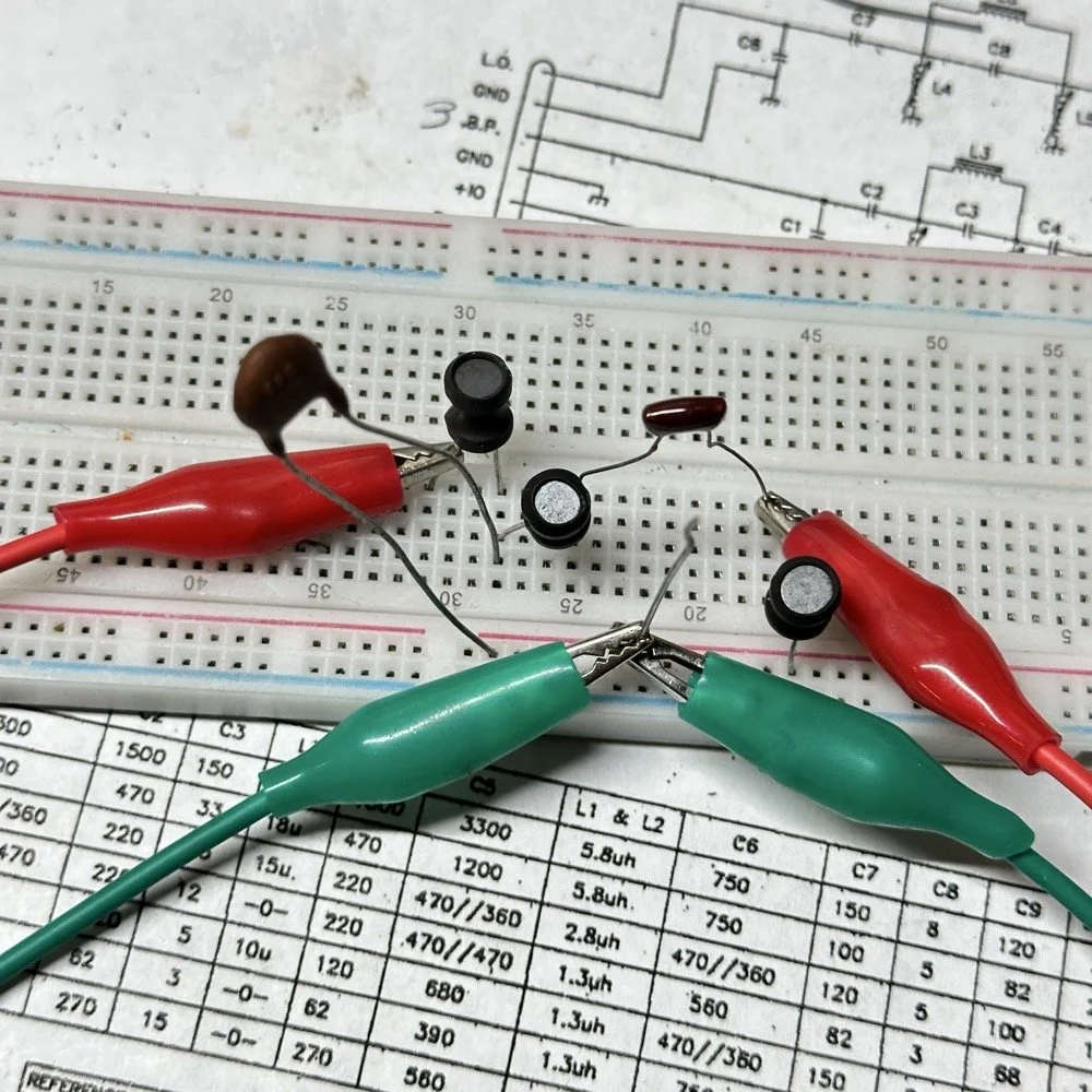
Below is the filter shape for this simple filter design too. It is a lot better than what I started with and I was able to build it with parts that I had available to me at the time. Could the passband be narrower? Yeah, it could, but I am not going to throw too much shade at this filter. This is what ham radio is all about in my book, experimentation. The marker is at 5.64mhz which is 250khz above the highest place I can transmit so I know this filter wont attenuate my signal and the radio will work as it should.
The original values for the filter ended up being wrong, but I simply did what I did in the previous filter build and just used it as a jumping off point and started switching out parts one at a time with different values. This tactic coupled with looking at the nanoVNA to see what the new part did to the filter shape gave me the results you see. At first I didn’t write down what I had done, but it quickly became apparent I needed to note what I had done and so things progressed much more quickly once I did.
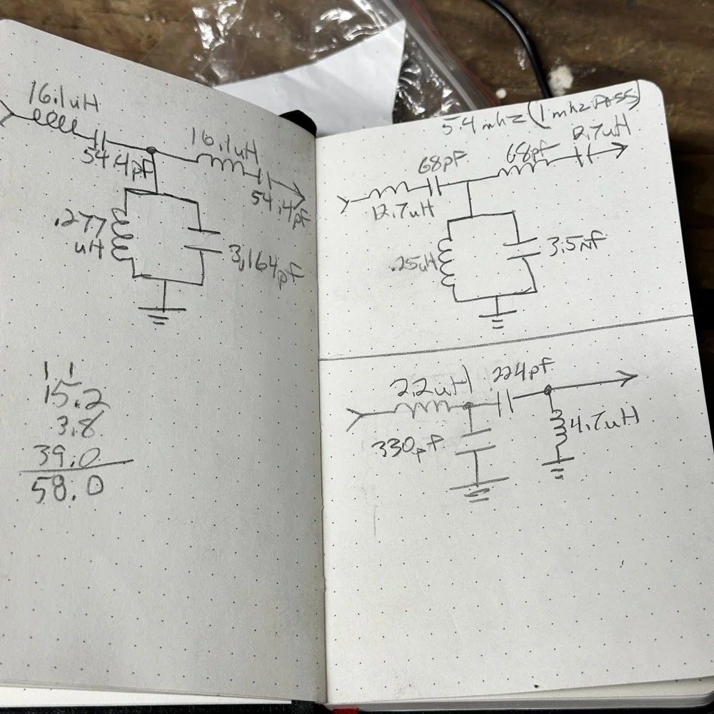
The above photo ( bottom of the second page ) is what I started with on this part and the lower photo is what I ultimately ended up with for the actual parts I used to build the filter. You can see where I was trying all sorts of stuff to get a working filter, these are not the only sketches either…
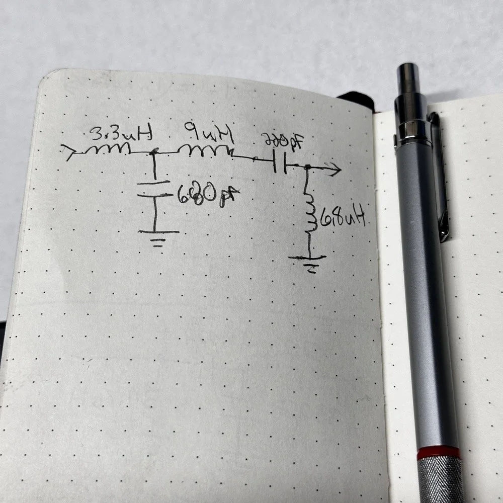
This is what I ended up with ultimately to get the filter shape above. The impedances are wrong, I am sure as I didn’t take them into consideration at all, but the radio is working correctly now (from what I can tell) and transmits almost at full power. Shoot, they could be right and I just got them right by accident, I really don’t know to be honest.
This is the output power draw now for the 60 meter module on the same radio as the 40 meter module previously compared. I can live with that! I checked it when I got into the shack at the house and it is a little over 35 watts into a 1.3:1 SWR load. That will work just fine for me. (Note: The current reading was into a 50 ohm dummy load at the workbench so I don’t know the exact current draw in the shack.) This radio will produce more output power too, I have it dialed back on purpose to about 40 watts for the 20 meter band module that I use with this radio.
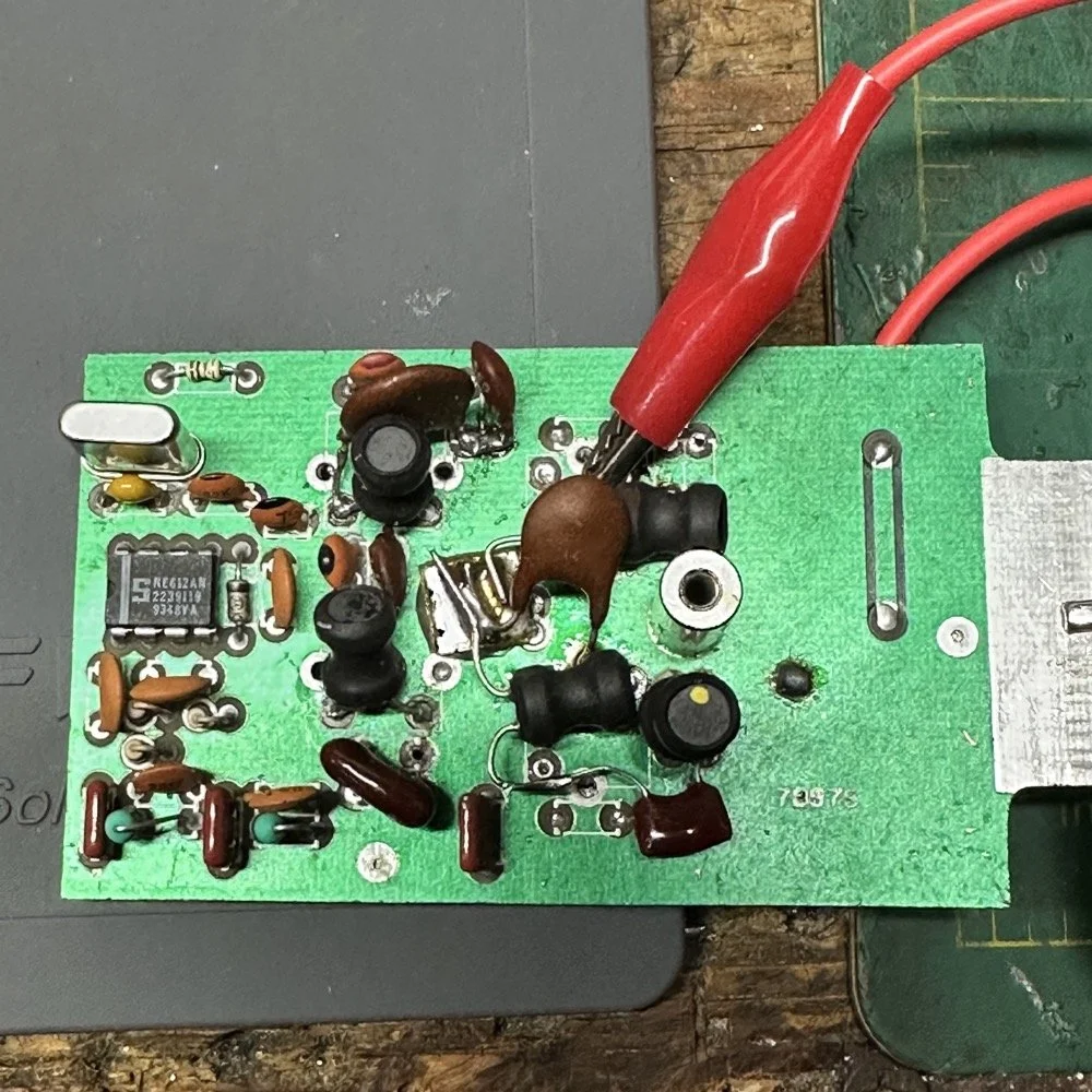
This is what the final filter looked like when I was finished building it. This looks a lot better than that mess I started out with above. Not overly complicated and generates a respectable filter shape. The radio sounds good too. So I am happy with this.
Side note about the above photo, I had noticed in my original filter design that the orientation of the inductors made a difference in the filter profile on the nanoVNA so I started marking them with a paint pen to remember the orientation. This filter didn’t seem to care too much about that for some reason but the original cared ALOT.
The side view photo shows something else the I have not mentioned in these write-ups. The filter has space constraints. The filter can not be taller than that metal post or the other circuit board with hit the parts and the parts can not go past the post either as that is the space for the output low pass filter from the other board. So parts count matters…
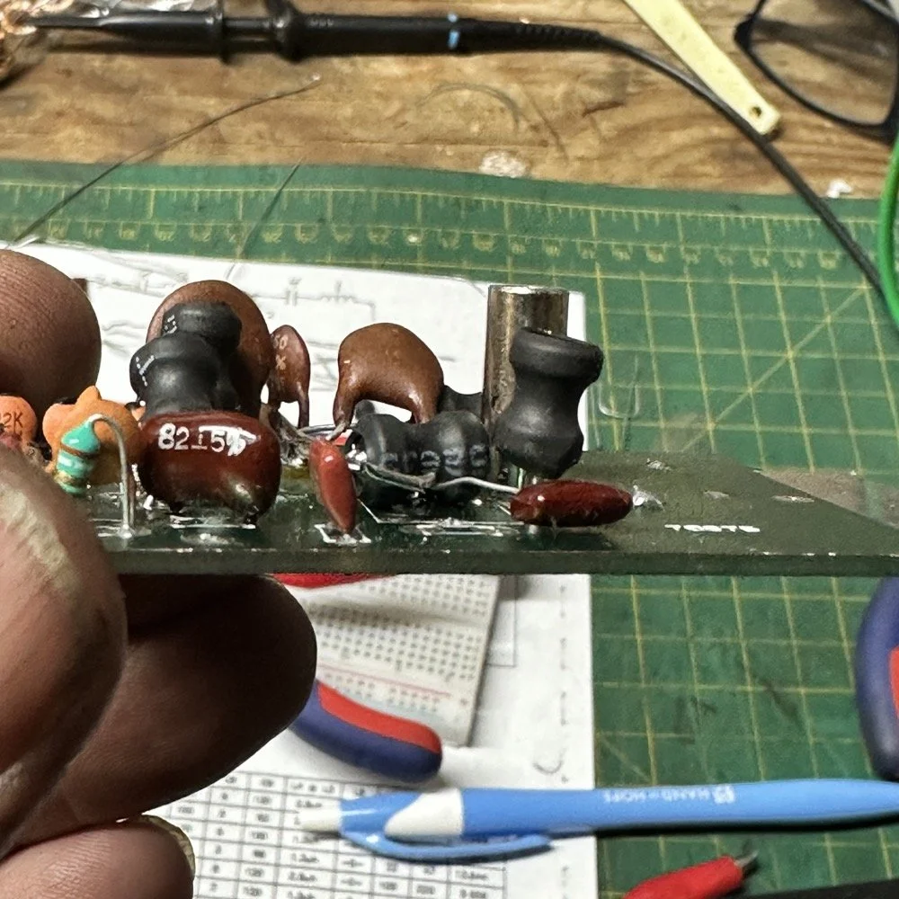
It feels oddly satisfying to see the finished module and to use it in the shack. All I did last night was listen to some stations having a QSO and how well it could hear them. I also dialed up the webSDR again and listened to myself calling CQ for a bit with no takers on a different channel. I know the radio is working as the listening station in Utah could hear me…
Tonight I hope to find a chance to jump into a QSO with someone and see how it sounds to them.
I hope this has inspired you to do something with your gear whether it be build a kit or modify a device to do something new or different or even to repair something you have that is not working now…shoot maybe you will learn something you didn’t know before! That is what has happened to me on this journey, I have learned a lot about how filters work and what affects them in use. I am starting to understand impedance matching the stages as well as insertion loss. A lot of things I never understood before are now becoming more clear. I also have a much clearer understanding about how the TenTec Scout 555 radio works as well…
Thanks for following along on this 4-part journey! If you build your own 60-meter module for the Scout 555, I'd love to hear about it. 73!
You can help support this website by using these Amazon Affiliate Links:
QRP/Portable Radios:
Antennas & Tuning:
CW Equipment:
Power & Accessories:
Organization & Transport:
BONUS ITEMS
WK4DS - David
![Ten-Tec Scout 555 60m Band Module Build: Final Filter Tuning & Field Testing [Part 3]](https://images.squarespace-cdn.com/content/v1/5d17806ce65eba00011667cb/c2e621e7-9bb7-4b40-b20f-7c5c2dc8be7d/IMG_1257.JPEG)
Ten-Tec Scout 555 60m Band Module Build: Final Filter Tuning & Field Testing [Part 3]
Today I took the newly minted 60 meter band module for the Ten Tec Scout 555 out on it’s maiden voyage to a POTA activation. I made a contact in the shack with it before leaving on my short trip to Florida so I felt confident it was ready to use. Today we are discussing what happened and what is going on from there with the 60 meter band module project. (Spoiler Alert: It kinda wasn’t really ready yet…)
Today I took the newly minted 60 meter band module for the Ten Tec Scout 555 out on it’s maiden voyage to a POTA activation. I made a contact in the shack with it before leaving on my short trip to Florida so I felt confident it was ready to use. Today we are discussing what happened and what is going on from there with the 60 meter band module project. (Spoiler Alert: It kinda wasn’t really ready yet…)
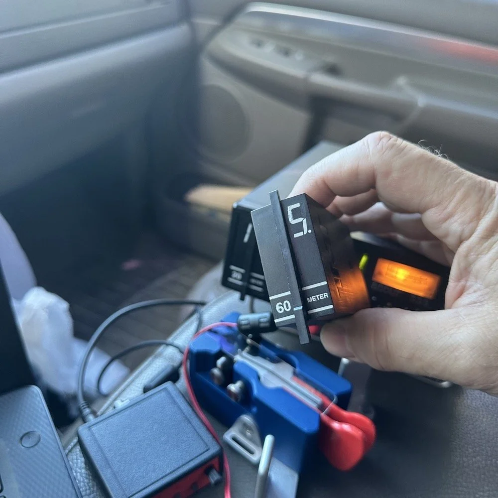
As you can see from the spot page report below, I was the only one on 60 meters this morning and it was roughly 9:45 (might have been 10 to be honest, I cant remember) local time before I got everything setup and running. This made 60 meters not a great choice to be honest for a daytime band. The 60 meter band is a great evening and really early morning band, but once the sun comes up these low bands tend to get really noisy. The band noise was quite low to my surprise today. I usually get a good bit of man made noise in this spot so I was pleasantly surprised when the noise floor was really low…or the band was closed. Who knows at this point?… I am starting to lean towards the band being closed as I couldn’t hear the FT8 crowd either, and those guys are ALWAYS on the band if it is open at all.
Undaunted by this and the lack of any kind of signal on the band, I setup and started calling CQ…and called …and called… then I finally got a station in North Carolina ( WA4CHJ - thanks for answering me, I really appreciate it. ) and with that I had a call in the log on 60 meters with a Ten Tec Scout 555!!! I can’t be certain this has been done by someone else, but as far as I know, I am the first to make that happen! After calling CQ for about 7 more minutes with no answers, I noticed that the ALC light was not coming on when I would key the radio and it was showing about 20 watts forward power on the built in meter. I checked the SWR and it was fine so it had to be in the module. I tried calling for a little longer and started getting an odd kind of “hashy” crackle on the CW sidetone and when it would make this sound the power would go up to the normal level and the ALC would come on…Upon this realization, I decided it would be better to sideline the module till I got back to the work bench next week instead of risk damage to the module or the rest of the radio. It also occurred to me that the RBN never heard me, not one time, while calling on this day so the band must have been closed…
You gotta admit though, that setup below is kinda sweet… Also the frequency is tuned off by the side tone (this is normal for the Scout 555) so it is actually on 5.3305 mhz in this photo. (I checked it with my Omni-VII before leaving home so I knew it was on frequency)
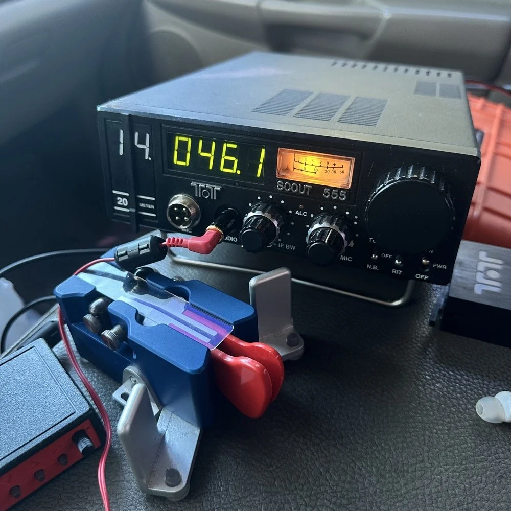
I setup a long wire today since my vertical will only tune to 40 meters with the home-brew load coil and I was a little strapped for time and just used an MFJ manual tuner instead. This allowed me to get a 65’ wire up in the air and a couple of radials and run with it. I was able to tune it well into the 60 meter band with the null covering the entirety of the band space so no tuner changes were needed as I moved around in the band.
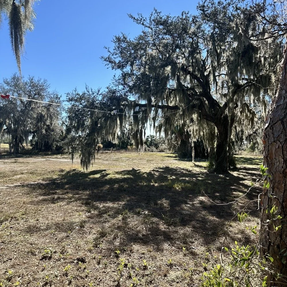
SIDE QUEST:
This little segment will be about the rest of the activation for my readers that follow those as well.
Today was a great day…once I moved to 20 meters! Turns out 20 meters was alive and well today with only about 6 CW activators on the band. This gave me plenty of room to find a nice quiet frequency as well as lots of hunters were out today as well. I tuned up on 14.047 mhz and started calling CQ, I think it took two calls max to call in a extraordinary pile up for me! The stations were deep and strong! I swept aside my normal pleasantries for the most part and compacted the closing to what I felt was a minimum and the calls just kept coming in! I worked 49 calls in 41 minutes! That is a record for me! At this point I literally called CQ one last time to make sure there was no one else waiting and got no replies so I immediately called QRT and shut down the radio. I was actually out of time and had to get the rig packed up since I needed to pick up the wife from class. This had to be the fastest 49 calls in the history of WK4DS amateur radio in my totality of radio… haha.
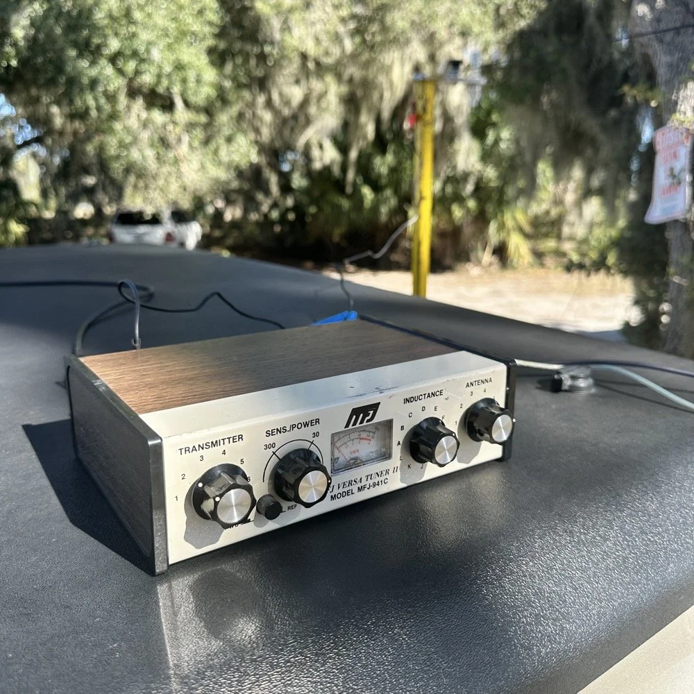
MFJ was a company that some complained about (Surely you have heard them called More Fine Junk) but to be honest, everything I have ever bought that they made has worked exactly as described and was pretty reasonable in price too. I hope someone fills these shoes for the future hams coming into the hobby, this little tuner is amazing for what is in that tiny little housing. It tuned this long wire just fine and didn’t need huge capacitors or inductors to do it. Not to mention it was really economical too. Good kit is hard to find so if you plan to do POTA in the field, I recommend one of these in the box of stuff, it WILL bail you out one day. This tuner has bailed me out a couple of times now…
A throw line, a weight (that I made in the machine shop out of scrap stainless steel) and 65’ of wire made for a lot of fun today.
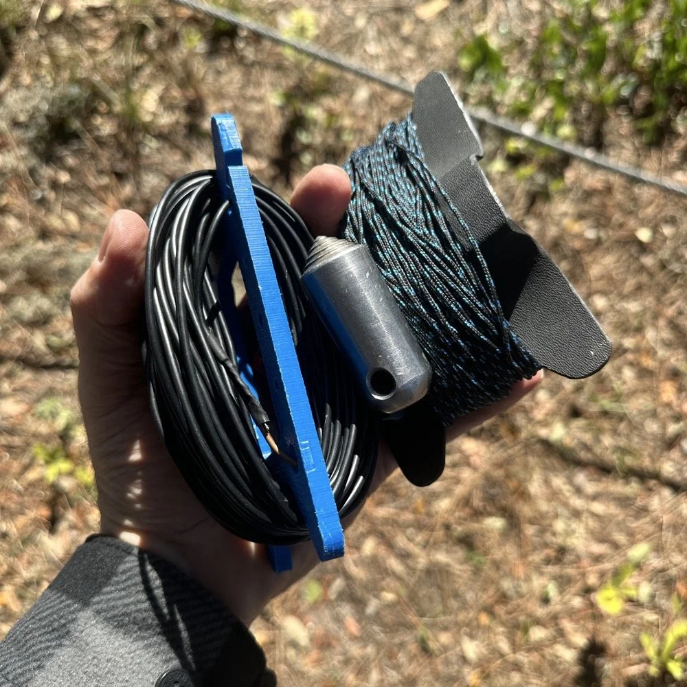
You can’t really tell it in the photos, but I did use my vertical antenna truck mount. I used it as the truck side anchor for the long wire and strung it up into the tree you saw earlier. This turned out to be really convenient I must say.
SIDE QUEST ENDED:
Back to the project at hand…
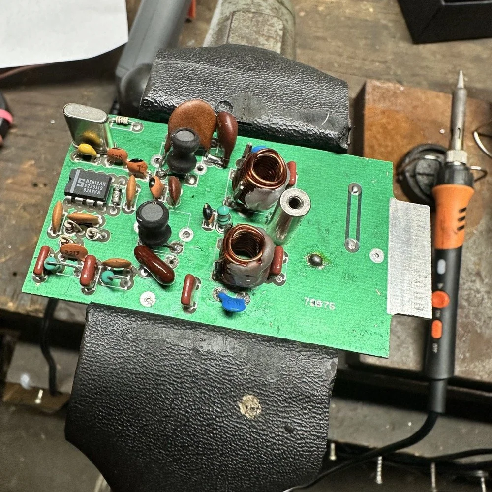
A week later and back in the shop at home with the band module on the work bench again and a Scout 555 in the shop now instead of the ARGO 556 to give me full power (40 watts) into the module (I pull the output power back to 40 watts to help protect the radio).
Now I can sort out the last of the details with the filters under full load. I am starting to think that the LO BP filter still needs some work as well as the signal level on the mixer output filter is REALLY high. I don’t remember the exact number but think of something like 700 or 800mV level instead of the 50mV that is supposed to be coming out. I tackle this problem first by building up the board like I had before so I could see the level coming out of the mixer filter. I had removed one of the impedance matching capacitors completely (750pf) without understanding what I had done and this was a big part of the problem with the level being so high. I did some simple math and came up with about 600pF instead of the 750pF that was supposed to be in the board since it was now tuned for 5.35 mhz instead of 3.55 mhz. I ended up using a 560pF cap and the level looked like the photo below on the base of Q16 in the radio. Remember this data is at this link if you need it as NA5N made these wonderful signal flow graphics.
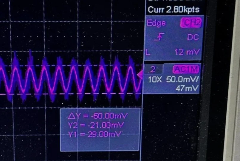
Right on the money at 50mv! I will take that everyday! All the noise you see on the signal is generated in the radio as far as I could tell, all the band modules I tried today looked like this on the base of Q16…or I was picking up the noise from somewhere else, I really am not sure to be honest with you. The output from the collector looked fine though so I don’t know what is happening here. I know this is good now as the frequency in the radio is stable and doesn’t drift. Those NPO capacitors paid off! (NPO means “Negative-Positive 0 ppm/°C” or more plainly, these capacitors are stabilized so they don’t drift in value with a change in temperature) My circuit doesn’t look exactly like the original Ten Tec filter but it does work.
Below is what I ended up with for the filter circuit. I added the one capacitor that was not in the original design (the 43pf cap) and this did seem to help with the shape of the filter so I left it. I drew my filter flow direction backwards from the Ten Tec drawing but you can see the differences from the 80m filter I started with below. Also a couple points of interest here. In my 60m module (formerly an 80 meter band module), the output from the mixer chip is pin 5 on my board and not pin 4 that feeds into the filter network. If you look at the spec sheet, this is fine as both pins are output pins, but it was a curious mistake in the schematic I found while troubleshooting my module. Another curiosity to me is that the schematic shows L6 in parallel with C8 (5pf) in the center of the filter. Not one single band module uses L6… at all. The chart underneath the schematic shows a -0- symbol on each one of the modules for L6, to confirm this, I looked in three different modules and none of them have this inductor in them. It isn’t present on the 10 or 12 meter modules either as they have a different layout for their filters. This was a provision that later was deleted I suppose. Kinda neat to find things like this while doing a project. Makes you wonder why they provisioned for the inductor but never used it. The board has two through holes for the inductor as this is where I placed my 15pf cap (which made adding it really convenient.) So it was obviously designed into the system to start with… Maybe someone who was an engineer at Ten Tec back then will comment.
Excerpt from original Scout 555 owner’s manual.
With that out of the way I moved on to the output LP (Low Pass) filter that the 50 watt power amp flows through to get to the antenna.
The above photo is of a LP filter out of an unmodified 80 meter band module I used for comparison. If you will notice the roll-off is right smack dab in the middle of the 60 meter band on this particular module.
The photo below is of the 60 meter band module sweep that I am building out of an old 80 meter band module. If you will notice I have the nanoVNA set to 5.430 mhz on the marker, and it is hard to see, but the signal is at 0.05dB which is basically zero losses at the highest band position possible. This would imply that the filter would allow the 60 meter band through just fine, but it would not…
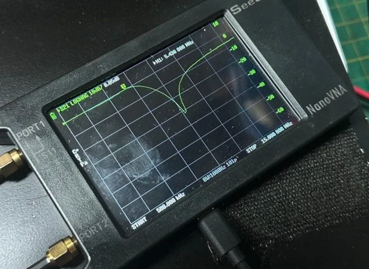
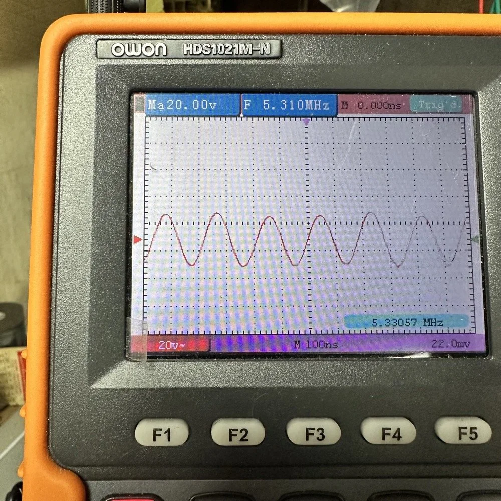
This is what the radio was sending to the dummy load after it passed through the LP filter module (above photo)… So to test this theory, I installed a different module (40 meters) and got what you see below… That is a little over 120 volts peak to peak on 40 meters. Yeah, you don’t change the output power of a Scout without a screw driver so the fact that the 60 meter band module I made is only letting a little over 30 volts peak to peak through it AND knowing that the 40 meter band module is passing over 120 volts peak to peak, tells me the 60 meter filter is choking off the energy and it is probably heating up the toroid inductors pretty good at the same time. I suspect that is what I was hearing the other day at the park when it was crackling after a while. I just hoped that I had not burned the wire on the inductors with this energy… If so I would have to rewind the inductors completely from scratch. Fortunately, I do have a roll of magnet wire I could do it with…
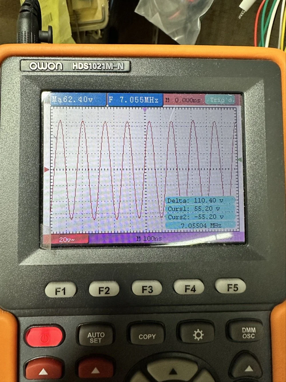
Into the final output LP filter I went (the one in the can) to see what I could do with it. The first photo shows the “can” the filter is shielded inside of to keep stray RF at bay.
The second photo shows what is inside of this can. This is also a photo of my completed filter with modifications to make it work on 60 meters. I found that this module had been tampered with once inside. Now to be fair, I did work on this module at one point to repair a broken inductor lead, but that was all. Now, I am getting much more serious while inside of the can…
I took another measurement with the nanoVNA and decided to remove the inductors and measure them with the LCR meter to see what it said they were. Turns out they were right on spec from the owners manual chart of 2.5uH each. At least that is what it looked like I read on the meter…haha. So I decide to remove an arbitrary number of wraps from each core (3 wraps to be more precise) and take another measurement to see what I had then. The meter showed them at 1.8 to maybe 1.9uH after pulling three wraps off. This put me right in the middle of 80 meters (2.5uH) and 40 meters (1.4uH) about perfectly. So I trimmed off the excess wire, scraped off the enamel so the solder would adhere to the copper and soldered them into the board.
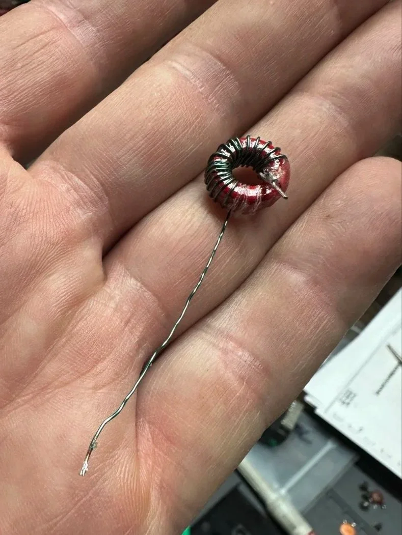
Back to the nanoVNA for another round of measurements to find it still wasn’t where I wanted it to be. The frequency was still pretty low at the roll-off point. I then decided to look at the capacitors to see what they looked like. This is when I noticed that the band module had already been modified somewhat as the center cap was sitting at about 850pf already and not the 1500pf it was supposed to be. I also found that the two shunt capacitors on the ends were also different from the 80 meter module for some reason. I pulled these back to 470pf each and checked it again and now the band pass was in the 6 mhz area, this should be far enough away from the operational band to keep me from having problems so I put it all back together and then checked it into the dummy load.
Success! I am seeing over 120 volts peak to peak coming out of the radio! Woohoo! I couldn’t believe it! I had full power coming out on 60 meters finally! This was a real special moment for me to be honest with you. After this, I reassembled the shielding on the filter network and cleaned up the solder flux and put the module back together.
With all that done, all that is left is to set it up with an antenna and make some contacts with it…
Yeah…about that… There seems to be a major solar storm coming in and has been since the previous day. This is a big deal as you can see from the report. It has shut down radio for most operations. I did call CQ for a while and at one point I heard WY7EE calling CQ but he couldn't hear me. Figures. I did turn up on the RBN so the signal was getting out to some degree in the evening. That was kinda awesome to see as well. I know I have signal going out too as the wattmeter is showing 40 watts forward power. (Remember I de-tune my Scouts to pull some load off the finals since they are getting old and I don’t relish the though of having to replace them for a 10 watt boost in power output) 40 watts will do just as well as 50 from what I have seen in the past… anyway.
The next day we had the storm to start fading out a little and I loaded up the webSDR on my computer and listened for my radio on the Northern Utah listening post. Once the time was late enough, I started hearing my signal on the webSDR! I recorded it and posted it to my YouTube channel as a short if you want to go listen to what I could hear. This is the link.
Link to video about 60 meter signal
Like I said, I am going to revisit the band pass filter for the IF again when I get back into town. I think that can be improved a lot. (my current design is too broad banded in the pass band to make me happy, I want to clean that up some more.) I will write that up when I get the chance to work on it—read Part 4 for the IF filter redesign. Thanks for following along on this little adventure and I hope to hear you on the air at some point. Maybe you will work me on 60 meters with my Scout…maybe…
73 and get out there!
All four parts are here:
- Part 1: Initial Conversion and Filter Design
- Part 2: Crystal Selection and Mixer Circuits
- Part 3: Field Testing and Troubleshooting
- Part 4: IF Filter Redesign (this post)
You can help support this website by using these Amazon Affiliate Links:
QRP/Portable Radios:
Antennas & Tuning:
CW Equipment:
Power & Accessories:
Organization & Transport:
BONUS ITEMS
WK4DS
David
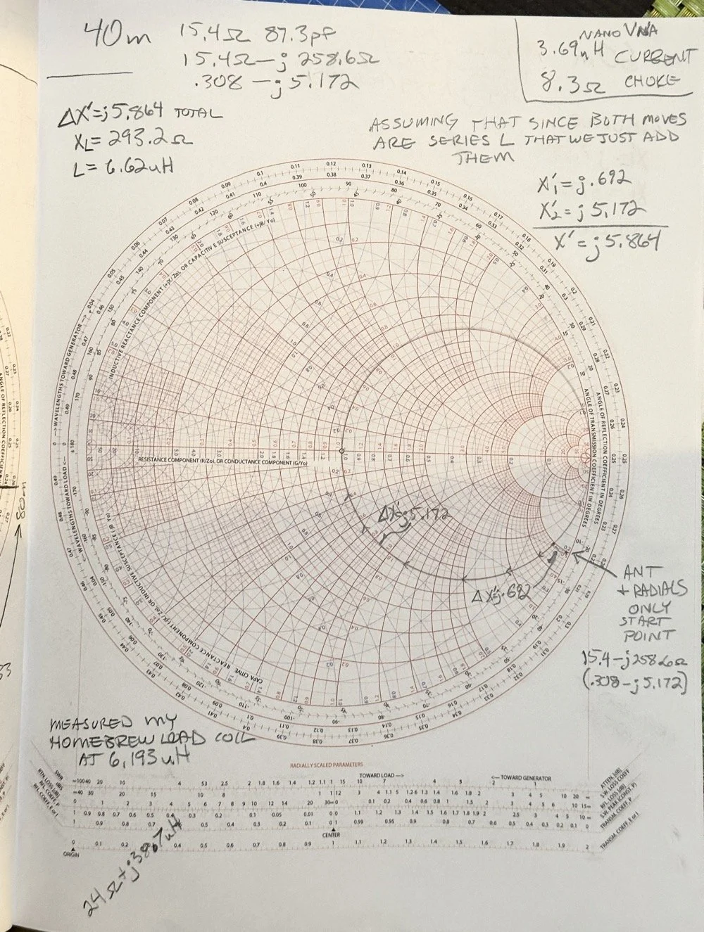
Smith Chart Exploration for Ham Radio: Building Impedance Matching Networks with DIY Inductors
Today finds the unsuspecting ham radio op perusing YouTube for something new to learn as it is really cold outside. He stumbles across a video about using a Smith Chart to match impedance and is intrigued…
What happens next is kinda terrifying…lol
Well to be honest, it is really kinda boring till you see how a smith chart sort of works and you start to learn how to use it to some degree. I have known about them for years, but have never understood how they work or even how to read them.
Today finds the unsuspecting ham radio op perusing YouTube for something new to learn as it is really cold outside. He stumbles across a video about using a Smith Chart to match impedance and is intrigued…
What happens next is kinda terrifying…lol
Well to be honest, it is really kinda boring till you see how a smith chart sort of works and you start to learn how to use it to some degree. I have known about them for years, but have never understood how they work or even how to read them. The other day though I landed on a video. This one shown below to be exact and I was hooked.
As you can see, if you watch this video, (maybe a couple of times), he explains it in simple enough terms that I actually understood what was going on finally! I did come into it with the understanding that the upper half was inductive and the lower half was capacitive from tuning my antennas with the nanoVNA. I would leave the smith chart on out of laziness and simply used the SWR graph to move the null to the operating frequency. But during this time, I started looking at the information presented on the display and noticed at times it would show capacitance and sometimes it would be inductance and also where the marker was sitting. This gave me the clue about what it was sharing with me. That was the extent of my smith chart knowledge though. At least it made sense to me. So the next logical thing to do was to order some smith chart notebooks from Amazon and a drawing compass so I could use said charts. While I was anxiously awaiting the new goodies to arrive, I started binge watching videos on smith chart use and taking away what I could from each video to add to what I already knew. By the time the paper arrived (I know I could have printed them off the web but the notebook format is really nice to be honest) {sarcasm}I was already a “master” at these “simple” charts… haha. {/sarcasm}
I will be honest with you. There is so much about these charts that I still don’t understand that it boggles the mind, but I have figured out how to use them for impedance matching and it is kinda awesome. I actually made the last few pages in my new notebook a cheat sheet based on the above video so I could reference it easily without having to watch the video over and over. I am absolutely going to build one of these fixtures when I get back home too. I would already have done it but I am not able to access my bench to put it together… So what follows is what you do when you don’t have that gear handy.
First things first, I bought a new toy. This is a 200 mhz “scope meter” but this one has another trick it can exploit. This is a actual dual channel oscilloscope AND it also has a arbitrary waveform generator as well! On top of the usual multi-meter functions as well. This thing has a lot to offer…till it doesn’t. It didn’t take long to figure out that the waveform generator doesn’t have the sweep function in it, this would have been nice to play with things. I can’t find FFT modes anywhere in it either so it can’t be a “poor man’s spectrum analyzer”. The little meter does have enough options to be really useful for what I was doing anyway so let’s get started… oh, it doesn’t come in this nice hardshell case. This is an Apache case from Harbor Freight. It is the perfect storage container in my opinion and I am happy to have it trimmed out like this. It didn’t take too long to figure out how to use the oscilloscope and I made a cheat sheet for it too so I can access useful features more easily in the future since a lot of it is hidden in menus due to the diminutive size.
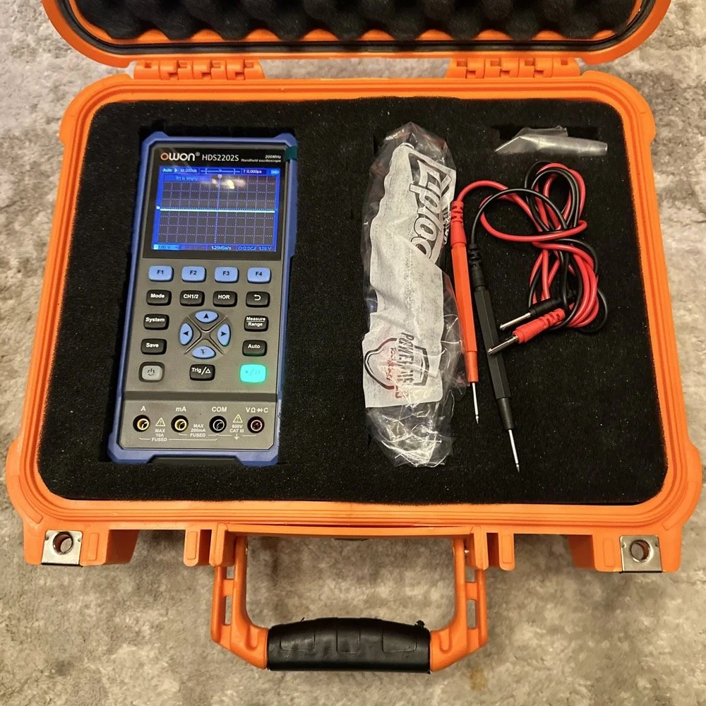
What you see here is pure desperation to see if I can make this smith chart stuff work for me. I am literally about to start making capacitors out of aluminum foil, a sheet of notebook paper and painters tape… Spoiler alert, it worked… You see, in another video I found on YouTube, there was this idea that you don’t need a LCR meter to measure your components as long as you have a known value device, a battery and some ingenuity. I also had a lot of time to play with this concept so here we are… I started by making a really big capacitor to start with to do a proof of concept and to see if there was enough capacitance to make this project work. Turns out there was way more than needed with the initial design, WAY more. So with the proof of concept made from three full size sheets of paper laminated with aluminum foil on one side of each one and then stacked so that the center sheet was one plate and the top and bottom were the opposite plate, I found I had made a .0034uF capacitor! This was more than enough to play with HF radio RF frequencies!!! Woohoo! Now this is all based on me being able to believe my new meter and later I find out that there is 17pf of stray capacitance in my meter and leads. Once I figure this out, and factor it into my math, it is all good but for now with this thing being 3408pf, I don’t think it is really a problem. The cigar box is there to use gravity to apply an even pressure to the “plates” and hold them at a consistent spacing as at this point, these were just three sheets stacked up. The top and bottom are connected to the black lead and the middle one is connected to the red lead. Also tested it with just on plate on the black lead and yep… capacitance went WAY down, so this style of capacitor worked pretty well to be honest. I could make it go up a good bit more by pressing on the cigar box too, I saw 5.0nF at one point while playing with it, that is crazy to me…
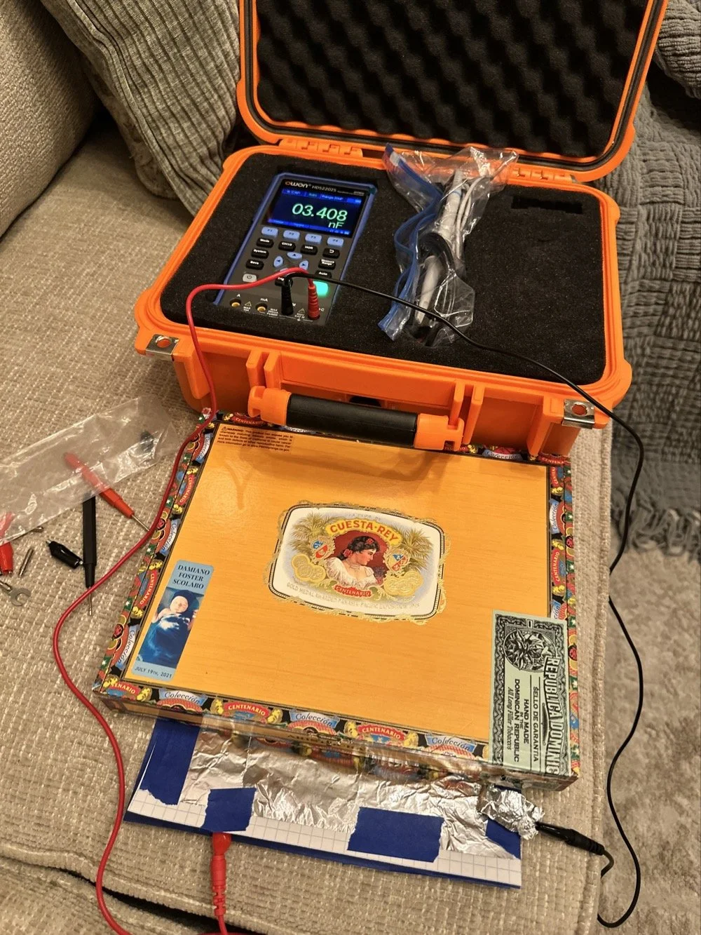
I had read somewhere about this idea to be honest. Well a cruder version of it actually. They made an impromptu antenna L network with two sheets of aluminum foil and a sheet of news paper or something like that. That made the capacitor and the inductor was wound on something found commonly in the house in the 1960s or 70s as well. They just used regular old romex house wire to make the inductor and it also worked just fine. Sometimes you just really need to have some “want to” and it can be done. I was a little more superfluous with my build as I didn’t need it to get on the air but rather as an experiment to see what I could learn.I honestly was really surprised to see how much capacitance I could get out of notebook paper and aluminum foil from the grocery store. This tells me that literally anyone that needs an antenna tuner, has one if they want it bad enough. You don’t have to have a Ten Tec 238 to be able to tune that random wire, you just need to gather some stuff you probably already have in the house…
Side note, I also finally acquired a new case for my POTA Scout 555 radio. I still need to finish the pockets for the band modules when I get home, but I now have it in a proper case and not just sitting in a cardboard box in the back of the truck! Also, I made another 60 meter contact today… to the same exact person that I made the first one with a couple weeks back! HAHA! I think we are the only two people on 60 meters CW in the mornings ever…
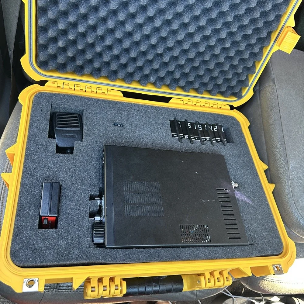
Here we see what I measured the other day while at a POTA park. What these numbers show is the antenna measurements for the band at the base of the antenna. I literally took the nanoVNA and adapted it to the antenna socket directly to eliminate the 50 ohm feedline from interacting with the measurement. As we will learn soon enough that you can use a piece of feedline (coax in particular) to move the base value around the smith chart should you need the starting point to be somewhere else. But I also learned something else about these starting point numbers below that I will share with you in a little bit.
At the top of the page, right next to the “40m” is what the nanoVNA reported that day at the park. (15.4 ohms and 87.3pf) you have to have two coordinates to plot anything on a chart so these are the two numbers you need to plot your starting point. Ignore the other notes as I am probably wrong on some of it and it actually makes more sense later. But the first thing I had to do was to turn these numbers into the proper numbers that the smith chart uses. This is called normalizing them. You see the chart is relative, you can assign whatever value you want to the center point on the chart and the rest of the chart is “relative” to this value. So if you were to work with 75 ohm coax and wanted to make an impedance matching network to work with it and having minimal losses, then you would assign 75 ohms to the center point. Since we use 50 ohms in almost all amateur radio (if not all) then our value is 50 ohms at the center point.
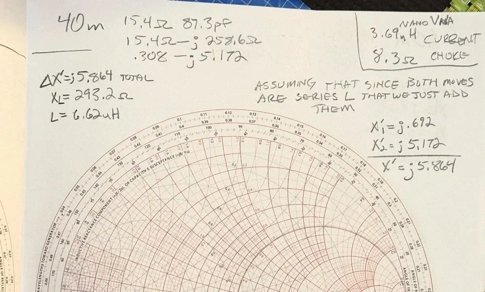
So here is my 80 meter plot (below) to get to a 50 ohm impedance from where it started at… yes… 1 ohm and 79.7pf capacitive! You see I am designing a matching network to couple my 50 ohm coax to a 18.4 feet tall telescoping vertical with a couple of radials thrown out on the ground. This is not even close to a matching antenna for the 80 meter band at all. Hence the terrible numbers to start with. Well, this was like those jokes you here from high school where you get something simple in the lecture in class about a subject then in the book it might show it with one more complication but the exam shows the Drake equation for the problem on the test! Well this is what happened to me as in the video above, the number in the video was closer to the middle of the lower half of the chart making for a more straight forward solution to the problem. I also did my admittance math wrong too if I am right…lol… since it is all inverted, but this doesn’t matter at this time. What you need to know at this point is that my problem lies outside the unity circle (that is the one I drew on the chart) and I need my “arc of movement” to cross this circle… it does but nearly at the infinity point (on the right side of the chart) which makes the math almost worthless… The reason the math gets pretty inaccurate is the numbers on the chart start getting logarithmic is value and so a small movement on the chart in this area makes huge changes in the values. You want your plot point anywhere else but here, yet this is where I am at in this blog post… haha
Knowing all this, I start this complicated, 3 position move to get me to the center of the chart. Mind you, I think this would actually work, but I am not sure if the math is mathing right at this time. (I am thinking the first move is a piece of transmission line to move the start point around the circle instead of an inductor and the second movement is also not a capacitor either so basically this whole thing is drawn wrong…lol) You will see why in a minute too as to why I dont know. The schematic for this movement is scrawled in the upper left hand corner of the notebook page if you wondered what it would look like to make this circuit. Two inductors and a capacitor to get to 50 ohms… how many antenna tuners have TWO inductors in them? I will help you out here… not many, if any. The number of inductors alone would make this a no go design for the most part unless is was going to be a one band wonder. Just remember I am pretty sure the math on this is wrong, the plot directions are correct, but I am thinking that the suseptance values are needing to be inverted to calculate the impedance for the two movements on the blue lines. Anyway, the point of this blog post is to show what is possible if you want to learn something new and it is not about the math around a smith chart…yet…lol I am diving back into the tutorials to figure out the blue part of the chart next.
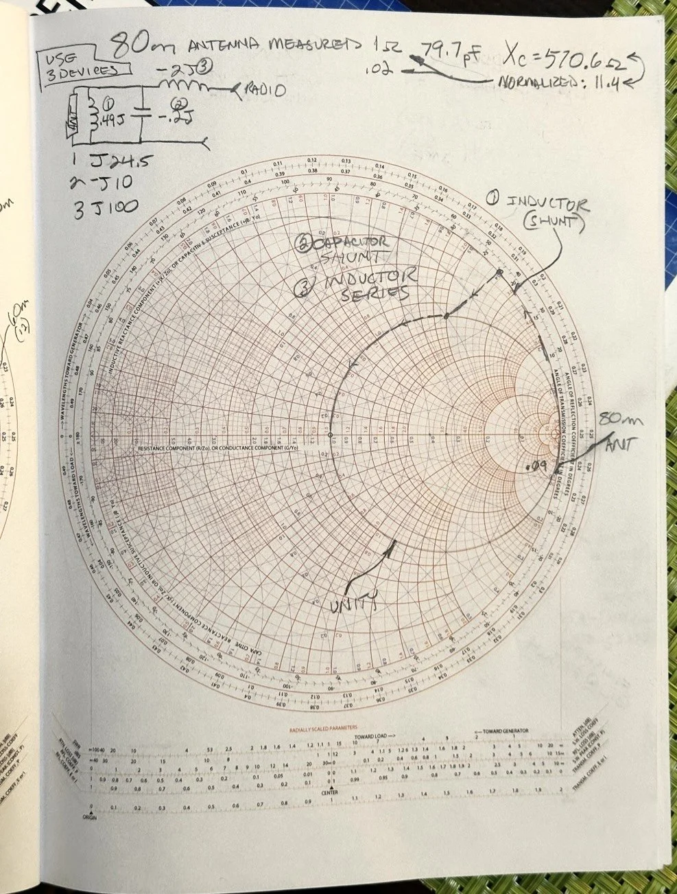
After I pulled my hair out for a while…wait, that don’t apply to me…I’m bald already… After getting over the frustration of trying to solve this problem, I redrew it on a fresh page and looked hard at it for a minute and had an epiphany… The plot point is not INSIDE the circle, or even anywhere closer to the middle of the chart at all, which would have been ideal, BUT it is really close to the unity line already. I mean REALLY close, so close in fact, I bet you could simply run around the unity line clockwise to the center point and just “eat” the misalignment on the horizontal resistance line of such a tiny amount and no one would even notice in the real world. You know what this matching network now looks like? A huge by large inductor is what, just a plain ole gigantic coil… Moving clockwise around the impedance lines (the red ones) indicates adding inductance to solve the problem. This is what all the antenna companies use when you buy a mobile 80 meter whip antenna if you think about it, just a huge load coil and nothing more. If you were to zoom in on this, I am guessing the resistive value when you get to the end of the arc, at the horizontal center line (which is the pure resistance line) would be something like 49.2 ohms or something close to that, literally less than 1.1 : 1 SWR maybe less to be honest.
Armed with this knowledge, I wanted to test this theory. So I now needed a way to make a coil to insert between the feedline and the base of the vertical to see if I had learned anything. Well I had this new scope / meter / signal generator widget and I had a way to make a capacitor, I then remembered a video where I guy showed how to measure inductors and capacitors with only a oscilloscope if you have one known device. Well, I have a capacitor that I made and I can measure it with the new meter, so that will give me the “known”.
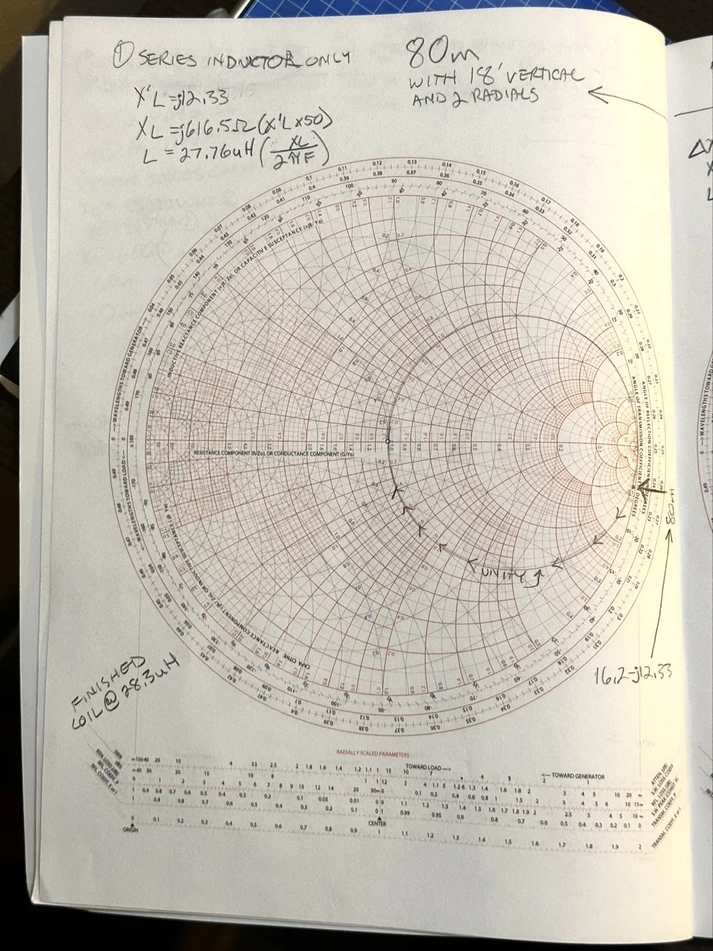
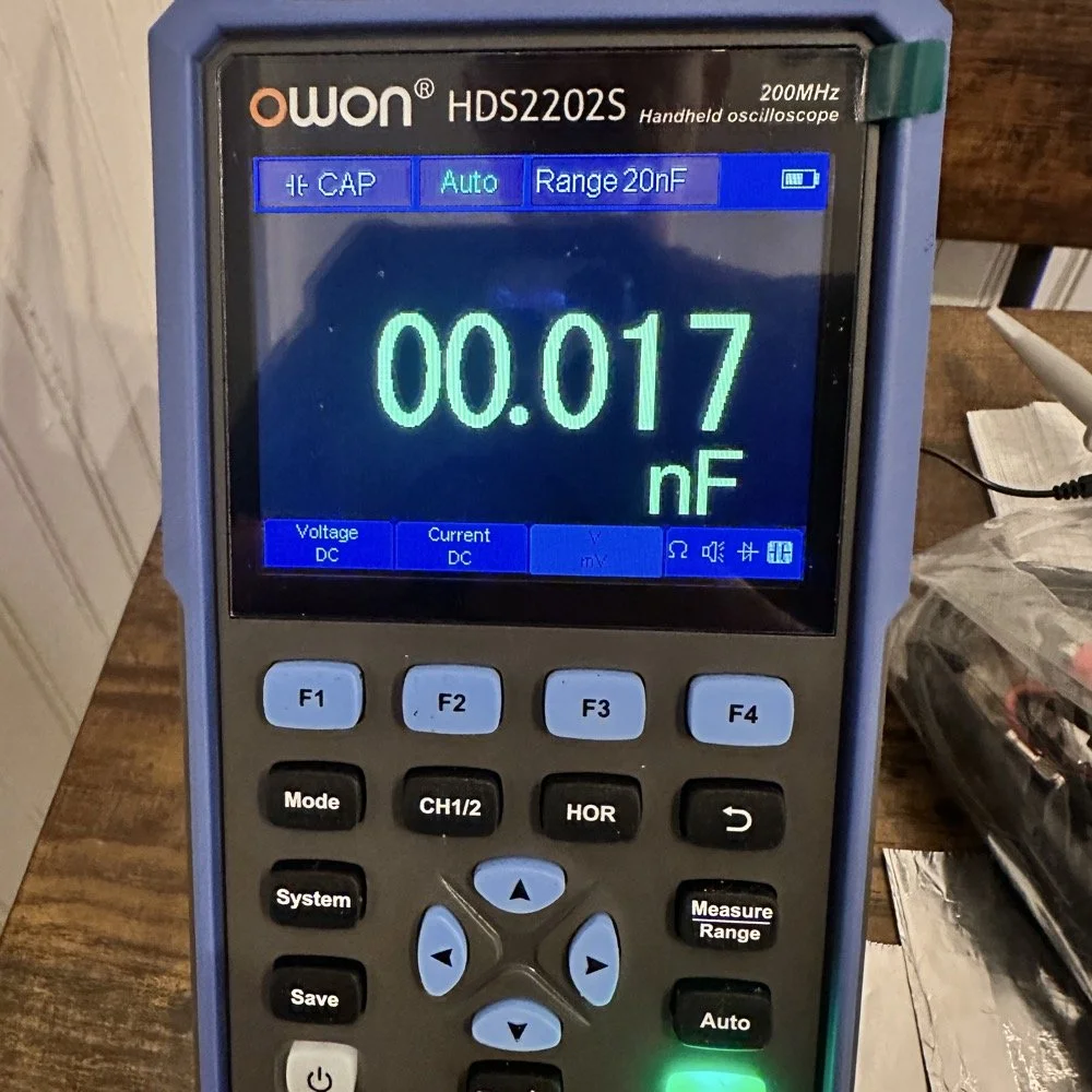
So I fire up the new meter and plug in the leads and find this. There is no way to “tare” out this number either so you simply have to subtract it from what ever you measure. I figured this would be pretty easy so I just went with it. Below is a photo while I was trimming the capacitor to a size I wanted. I was looking for 100pf and as you can see below on the meter, I was getting close. This is measuring right at 121pf in the photo. I would trim off the edge of the sheet and then check it again, rinse and repeat till it was close to what I wanted.
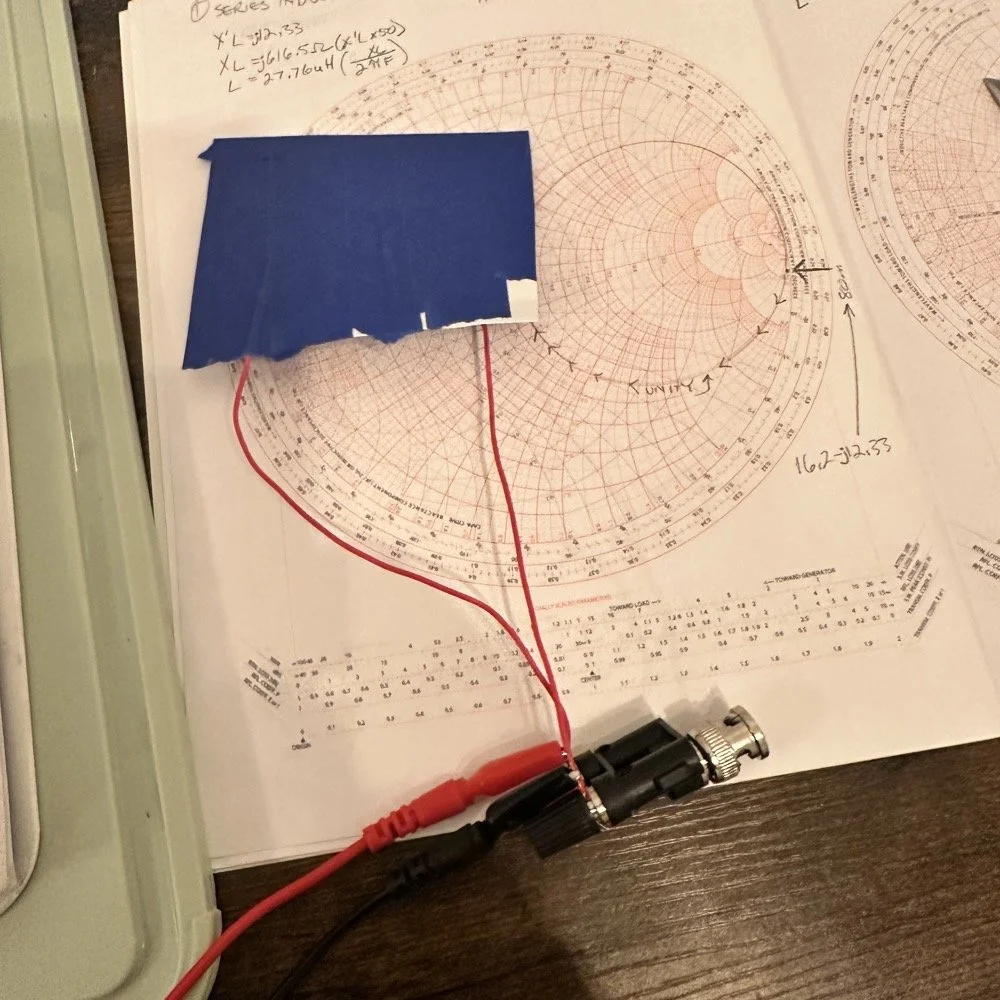
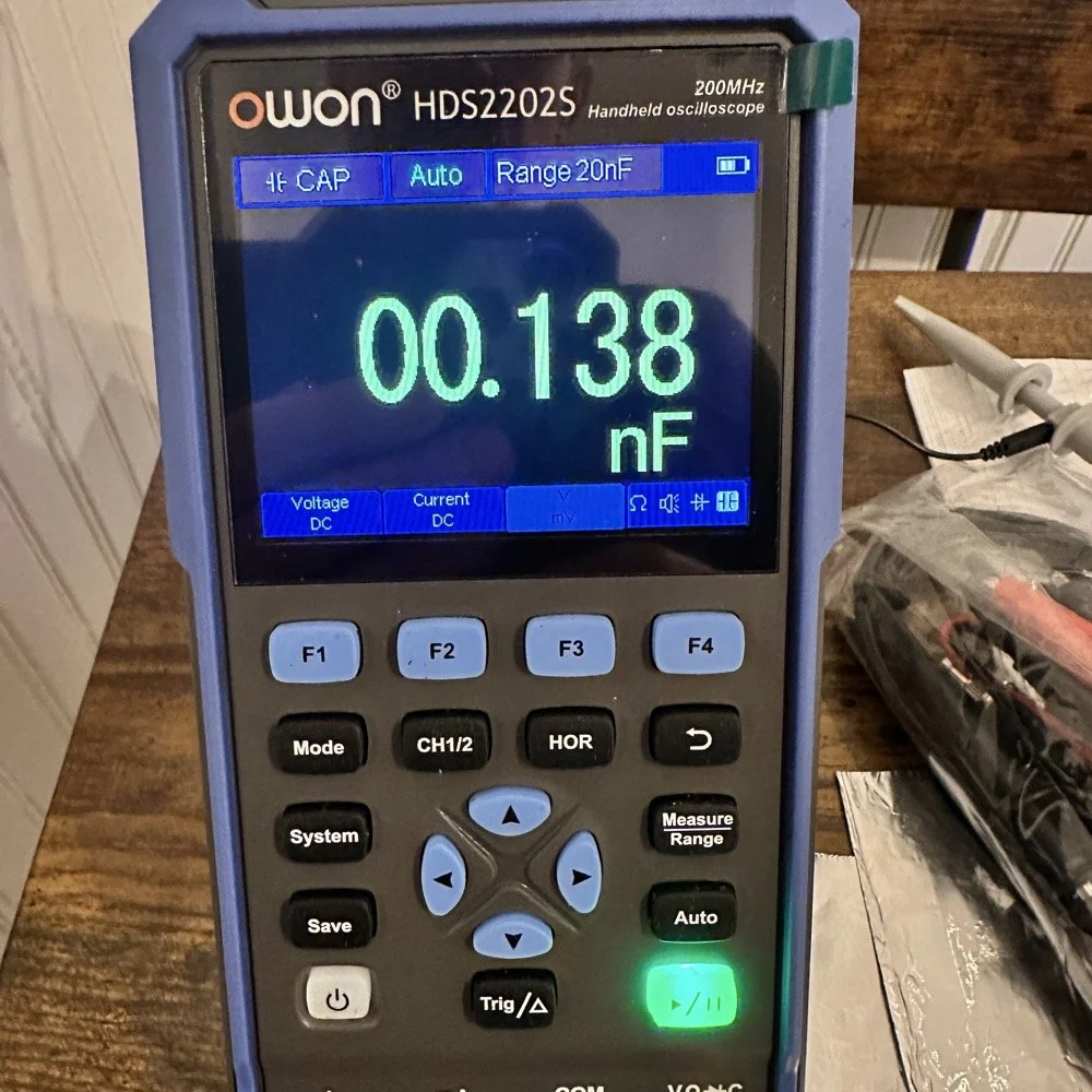
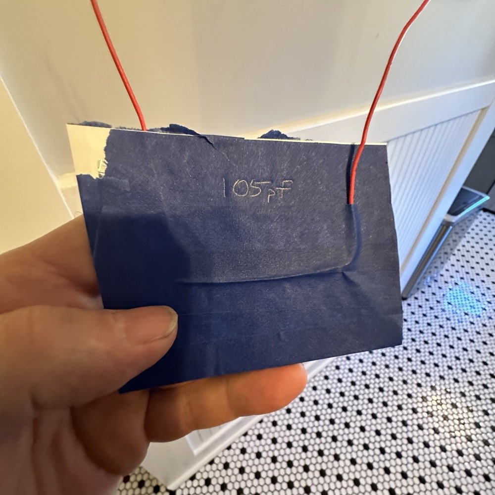
Once I had my brand spanking new capacitor made and trimmed to size (105pf), I setup a test fixture to do my test with. The test fixture is also expedient since it is all that I had was one of those “BNC to binding post” adapters and just used it as a sort of bread board to attach all the parts to the system. It worked, it was pretty janky, but it worked. All that we have here in reality is a parallel tank circuit. It will resonate at one frequency natively and I can measure that and then use a simple online calculator to see what the inductance is based on my capacitor value and the frequency of the tank circuit. How do I get it to resonate then? Simple, use a battery…
In the other video I had recently watched he showed simply setting the scope to trigger off of a voltage level close to the value of the battery which will allow the scope to capture the ringing of the tank circuit if you pulse it with a battery. I just took a AA out of my pocket flashlight and used it, set the trigger to normal and set the trigger level to about 1 volt and started touching the battery to the two red wires going out to the left in this photo below. This biased the tank circuit (simply applying a dc voltage across the capacitor and charging it) and I was rewarded with what you see below on the scope in the below photo. To be perfectly honest with you, I had done so much wrong in this process that I was honestly surprised that it worked. I even had to show it to Teresa and she had literally zero idea about what she was seeing here, but I had to show SOMEONE that it has actually worked!
The ringing the scope captured is nice and clean and I was able to measure the period of the sine wave at 172 nanoseconds. Transforming the time into a frequency is easy, you simply invert the number or divide 1 by .000000172 and you get 5,813,953 hz. This frequency is not relevant to the ham bands but is only useful in telling us what the value of the inductor is, which is what we want anyway. As you can see from the screen shot below, this inductor is 6.245 uH (micro henrys). I did the plot on the smith chart for 40 meters for this antenna and came up with almost exactly this number, I came up with 6.62uH on the math. This also makes sense as I did this physical coil for the 213” (17.75’) WRC vertical and not this one that is longer that I am using now 221” (18.4’). Another possible reason for the variation from the measured and the plotted values is that my capacitor value could be slightly different from being moved around or being in proximity to metal or some such. You could touch the capacitor with your finger tip and the value would change so this is probably part of the variation…
I made this actual load coil by guessing to be honest, I did use the nanoVNA as a SWR meter when I made it and I would take off a coil or two and measure it and I simply walked the null in on the antenna for 40 meters that day. Now I know how to use a smith chart to do that math ahead of time. That is pretty cool.
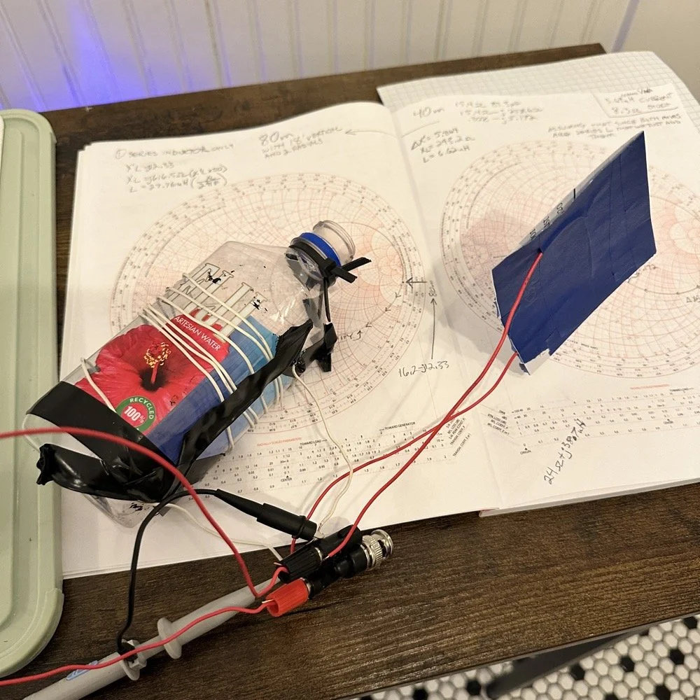
Literally using trash to resonate as a tank circuit is kinda cool to be honest with you. The wires for the capacitor are simply taped to the aluminum foil, nothing more as I didn’t have a way to solder them together or anything like that. This was truly a temporary test fixture for experimentation.
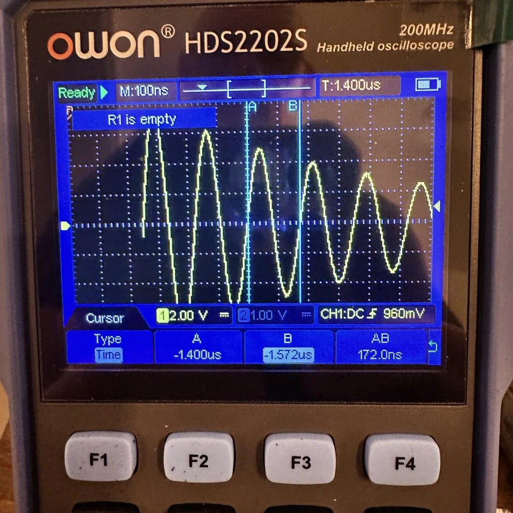
The next logical step was to make an inductor for 60 meters and to hook it up to the antenna and measure it with the nanoVNA to see how close I could get it. This is where things started to go south…
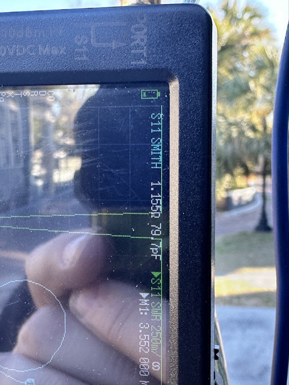
First of all, I had problems replicating the same resistance and capacitance from that day at the POTA park. The photo of the VNA above shows what I am talking about. Now it is 1 ohm… yeah basically a dead short for the RF. But more importantly it is different from the day of my test which was about 10 ohms (if memory serves me) but basically this doesn’t matter when you get to the region of the smith chart that this plot is landing in. The capacitance is what really drives this position between these two numbers and it was virtually the same. The amount of inductance will be more for 1 ohm but not a whole lot more.
Well what happened when I hooked up the coil and the vertical and stuff in the driveway was a whole bunch of nothing! It just made a circle around the outside of the smith chart, which is bad if you don’t know. You want your line to go through the center of the chart at the frequency you want to use and if it goes around the outside it ain’t going through the middle!
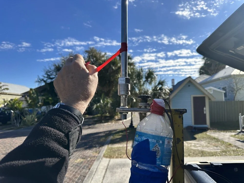
Deflated that I had probably done all that math wrong…again… I was about to throw in the towel when the wind blew and the plot on the nanoVNA moved towards the center! What just happened??? I start messing with this and that, as you can see in the photo above that the coil output wire is just poked into the coax port on the antenna. This has to be the worst way to make this connection, but if this is all you have, then this is what you do…
I could grab the vertical and that would make drastic changes to the smith plot, so I thought about moving the antenna without touching it and I found a roll of electrical tape and used that to tug on the vertical as it is in a QD mount (which is not a great connection to be honest that I have found). I even cleaned some stuff to no avail, but when I put the tape on the antenna and pulled it in certain directions, I would get the plot you see below. Notice the marker is at 5.340 mhz and at 55.2 ohms and just 1.49nf capacitive. This is less than 1.2 : 1 SWR and I am sure that it is off a little because of the system losses at this point. All the loose and dirty connections along with the random radial placement (I find this makes a pretty large difference with my systems) made getting repeatable results almost impossible. This told me that the coil worked though and that my math was not wrong! I had actually learned something here!
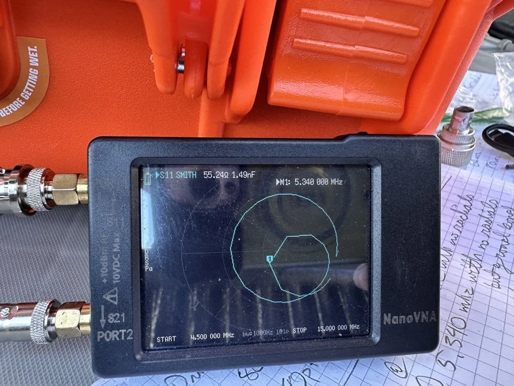
Once I figured this out and took a couple of photos for the blog, I tore the system back down and put it all away so I could get started on this write up about it. This has been an amazing process to do this and I learned way more than just how to do impedance matching with a smith chart. I learned that my system is way too inconsistent to simply make a coil and expect it to work in the system. If I had all the parts hard mounted in place with corrosion inhibiting paste on the connections then I could calculate this coil and it would drop right in. I was blown away by this and cant wait to find another use for my smith chart notebook. I hope this has helped you in some way either by simple entertainment or by learning something about smith charts and antennas, or maybe that there are YouTube videos about how to do this sort of stuff, either way, thank you for reading to here and I hope you come back for more of my ramblings in the future!
You can help support this website by using these Amazon Affiliate Links:
QRP/Portable Radios:
Antennas & Tuning:
CW Equipment:
Power & Accessories:
Organization & Transport:
BONUS ITEMS
73
WK4DS - David
![Building a 60m Band Module for Ten-Tec Scout 555: Crystal Selection & Filter Design [Part 2]](https://images.squarespace-cdn.com/content/v1/5d17806ce65eba00011667cb/1768486316134-5KK47YMDB3P45BK25B4N/IMG_1141.jpg)
Building a 60m Band Module for Ten-Tec Scout 555: Crystal Selection & Filter Design [Part 2]
I figured the the mixer’s bandpass filter would be the same as the IF filter but turn’s out I was wrong here. I looked at the existing part values on the chart for 40 meters and 80 meters (remember that part about not having a formal education in this stuff?) and simply decided that the inductors were again too big and I needed them to have a slightly lower value instead.
Well, if this is the first post of my blog you have found about the 60 meter band module, please Read Part 1 for the complete background on this project. or a lot of stuff is not going to make sense…haha.
The donor about to undergo surgery to become a 60 meter band module.
As you know from last week, I was able to get all the filters updated except the output bandpass filter for the mixer and changing the crystal, so let’s get into that today.
I figured the the mixer’s bandpass filter would be the same as the IF filter but turn’s out I was wrong here. I looked at the existing part values on the chart for 40 meters and 80 meters (remember that part about not having a formal education in this stuff?) and simply decided that the inductors were again too big and I needed them to have a slightly lower value instead. This is where things get engineery..is that actually a word? It should be. I started by simply using an online calculator to figure the values for this filter based on the chart from NA5N’s Website and my own simple math of a mixed product of 11.442 mhz. It falls right in the middle of the 80 and 40 meter LO frequencies on his chart. So now I needed a crystal…
Luckily I didn’t need matched sets like when making a crystal ladder filter so I was able to find 9.218 mhz crystals on Digikey for reasonable money. The calculated crystal frequency I came up with was 9.242 mhz to land at 5.300 mhz. This radio will absolutely transmit out of band and it is the responsibility of the user to stay in legal band space so I figured this would cover the entirity of the 60 meter band. The NA5N chart shows the PTO minimum frequency is 2.2 mhz so that is where I started my math.
2.200 mhz (PTO min.)+9.218 mhz (PTO XTAL)=11.418 mhz (LO) - 6.142 mhz (IF) = 5.276 mhz
The entirety of the 60 meter band is from 5.3305 mhz to 5.405 mhz so this will work perfectly fine.
All this math starts to make sense when you look at the chart at the bottom of this page. That is why I keep linking it…haha. So I build out the band pass filter and install the new crystal when it comes in and … nothing… Well, it did something actually. It would not lock onto the frequency at all, it would attempt occasionally, but most of the time it would just scroll numbers on the display of the radio. It obviously was not working. I was sure I had built the filter right… (turns out I was dead wrong…again…I am starting to see a pattern here…haha).
As I would soon find out, I built the filter for the 40 meter IF by accident. At this point I had a lot of numbers floating around in my head and scribbled on various pages laying around the bench and one was where I had done some of the math around the 40 meter circuit for some reason and I inadvertently used those numbers to make the inductors with. Couple this with a trip out of town for a week and you will see where I lost my train of thought. Once I returned from the trip I had just two days before leaving again to see what I could figure out.
Well, this is what I figured out.
What you see above is a frustration point to be honest. I studied the print long enough to realize I could bring the circuit to life if I had a signal generator and a power supply. To get this to work I soldered several small scrap clippings from component leads to the board in strategic places to be able to connect leads for various devices and you get what you see above. I immediately went down a rabbit hole on signal generators and ended up with a UNI-T UTG962E and it arrived THE DAY BEFORE WE LEFT ON OUR TRIP. I get it going and power up the circuit with the 10 VDC bus and then inject a 2.2 mhz signal from the brand spanking new signal generator into the line (simulating the PTO) to see what I would get at the output… well… nothing. I checked the crystal and I had a clean 9.218 mhz signal at about 700mV going into the mixer chip but my 2.2 mhz injected signal was 50mV (the signal level based solely on the output shown on the block diagram going into the receiver control board as the data sheet for the chip I found didn’t show a signal level threshold that I could find.). This was obviously too low and I started turning up the signal generator and nothing happened at first. I was at 700mV of signal level coming out of the generator and I was getting nothing at the output of my filter. So I start walking it back to the output of the generator. I didn’t have anything at the output of the mixer chip as it turned out, so I check the inputs to the chip on the chip directly and the PTO input was almost non-existent. Turns out that the output impedance of the signal generator and the input impedance of the low pass filter for the mixer chip on the board must be different as it was dropping the level pretty dramatically. (This is something else I have learned while doing this project, you have to observe the impedance between stages or it wont work. ) So what do I do to solve for this? (Remember again I have almost no formal education in this area of expertise) I simply put the scope on the output of the mixer IC itself and slowly start turning up the 2.3 mhz amplitude till Eureka! The mixer sprang to life and I had a product!
Note: I am using a different value here for the PTO reference signal because I didn’t notice that I had changed it till I got the mixer working. But it is fine as the PTO operates from 2.2 mhz up to about 2.7 mhz anyway. The key was getting the bottom of the mixed product below 11.425 mhz when the PTO is at minimum. This will allow tuning through the 60 meter band. But this is why the number in the photo below is 11.520 mhz and not 11.425 mhz.
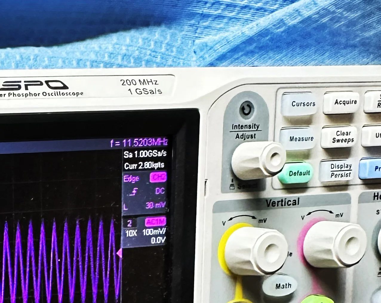
Now that I have a signal coming out of the mixer IC, I need to see what it going to the receiver control board. You see on the signal path drawing from the NA5N site that he states it should be 50 mV or so there. Well I had nothing coming out of the band module at all. I start looking at the filter and this is when I figure out the filter is all wrong. Back to the drawing board again. I take the week long break and during this time away I dwell on what I had learned and spend even more time trying to learn how this bizarre filter works. It looks somewhat like a regular band pass filter but there are elements that don’t make sense to me. I spent a considerable amount of time studying this problem and decided to order some inductors and when I get back I could replace my home brew ones and see if I had done something wrong there.
Fast forward a week and I went home and had about 5 hours total to figure the whole thing out or it would wait yet another week… I start by replacing the two home brew inductors with two 2.2uH inductors from the variety kit I ordered. Still didn’t work, so there must be something wrong with the capacitors too. All of the caps at this time were class 2 capacitors so that would turn into a problem as they warmed up, but this thing was not working even when it was cold, so the values were wrong is all I could figure. The most logical thing was to strip them all out and start over. I had now gotten my hands on some NPO caps too, this allowed me to build out the filter completely with the correct rating capacitors thereby giving me the confidence that once it is working, it will hold value.
My first batch that I bought was a literal double handful of random NPO capacitors (and a few other ratings mixed in for fun) thrown into a box from eBay. I knew what I was getting so I also picked up some divider boxes to sort them when I got time. Now they are all sorted and I know where to find what when I need it. Of course, I don’t have every conceivable size to choose from but I do have a large assortment and can get by with most projects with what I have. Things like this are what I wished I had learned in trade school… I guess I should have chosen college instead…you know what they say about hindsight though...
The photo of the board above that shows all the leads connecting to temporary test points I soldered to the board has these capacitors on it. They are temporarily soldered on as I am experimenting with various values in different locations to see what will get me to where I need to go.
I tried to use the online calculators but this filter doesn’t fit into any of those models and all the outputs from those tools were not working for me. It looks like the coupling capacitors are also used to also limit the signal level from stage to stage as well. Correct me if I am wrong in this assumption, but tiny little 5 and 8 pF capacitors are not letting a lot of energy through them, even at HF frequencies and there are two in this filter circuit. I can only assume that they are also using these to match impedance as well or a larger value would couple the stages with more signal. Anyway, I was stumped and asking the internet for help is literally begging to be slandered and chastised for being stupid, so I didn’t even bother with that option. That only left experimentation and experimentation is what I did. I put all sorts of outlandish caps in this filter and found success doing it this way. It took me a few hours, not gonna lie, knowing how to calculate these sorts of things would have been immeasurably easier, but I was able to get the signal on the output trace of the band module and it had decent signal level too! Honestly, I am going to revisit the output signal level when I get back home (I may have already done it by the time this goes live on my site) and see if I can attenuate the level somewhat as it is higher than what the base of Q16 on the receiver control board shows in NA5N’s pictogram.
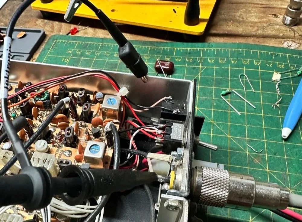
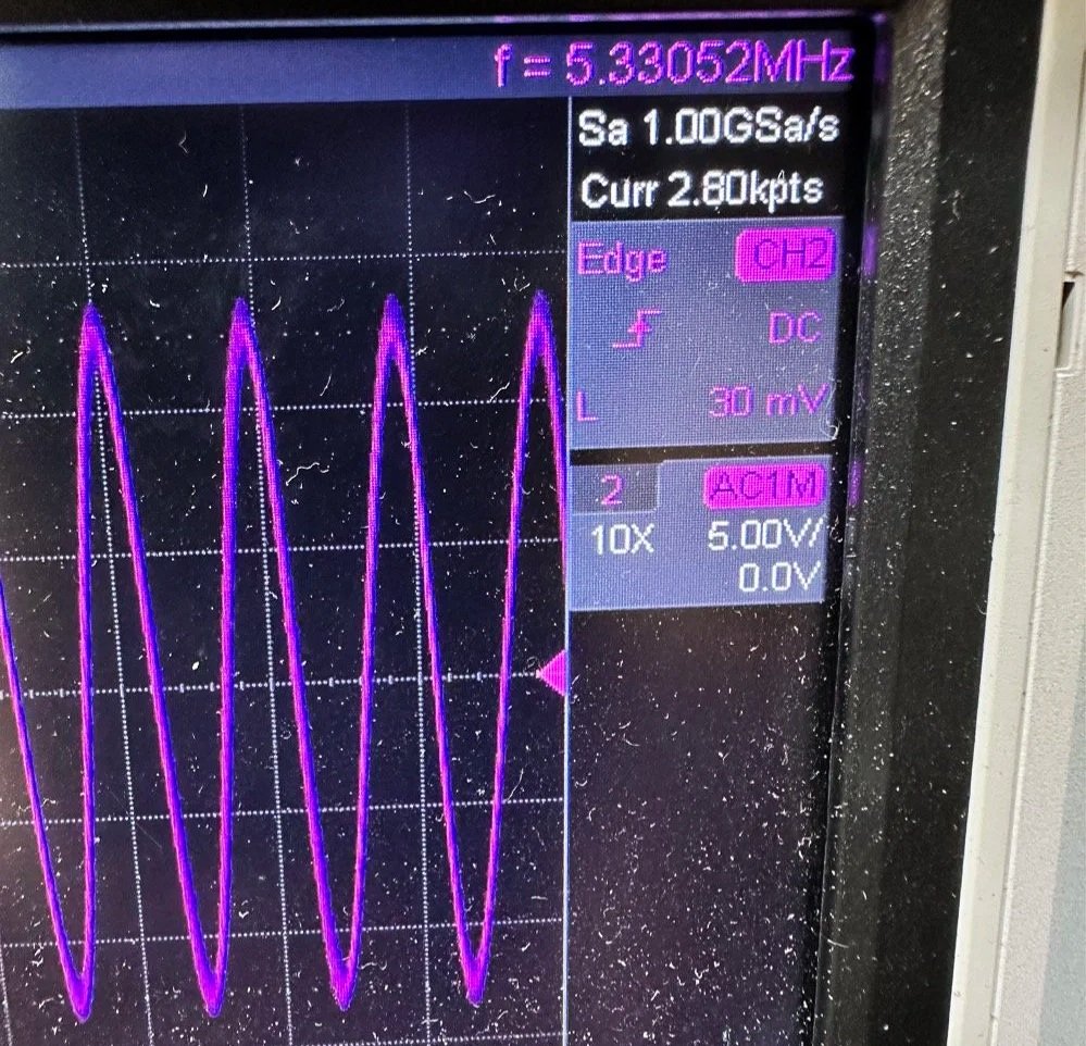
What you are seeing above is the output of one of my Argo 556 radios that I used as a test bed to check the signal levels and such to see what was going on with it. As you can see I simply connected to the output of the radio and looked at the signal going into a 50 ohm dummy load. I did the math (I know, I know… this has not been a great idea for me in this blog post… lol) and it comes out to about 1.8 watts and not 5 watts for this radio (I have not attempted to turn up the transmit power on this unit yet either so it might simply be turned down or something like that. Let me know if my math is wrong here, but 27 volts peak to peak and 50 ohms should give me a power level of 1.82 watts at the antenna connector?
Power= peak voltage (13.5volts) divided by the square root of 2 and then that is divided by resistance.
All that aside, I took the newly minted 60 meter band module up to the shack and setup a Scout 555 and connected it to my home antenna. Tuned the antenna up and started looking for a QSO. I promptly found one and had a short ragchew with VE3USP in Ontario despite some QSB along the way. It works perfectly too. I do have to dial up 600 hz to be on frequency as it is a Scout 555 after all, but that is not a problem!
So I am not completely finished with this module as of yet. I still want to look at that output filter from the mixer and tune it some more. It is close, but it is not right as the signal level is too high. I found I missed a couple of capacitors when I dismantled it to clean it that need to be NPO capacitors instead of what I currently have in place as well. I would also like to improve upon my terrible painting skills if I could figure out a way to do it…lol Seems acrylic craft paint might not be the best solution here…
Next week we get into what happened when I took it to a POTA park… hint: I brought it back home and got inside a little more to fine tune it…. I discuss this next week and show you what I came up with for the mixer output filter ultimately.
To read the other parts:
- Part 1: Initial Conversion and Filter Design
- Part 2: Crystal Selection and Mixer Circuits
You can help support this website by using these Amazon Affiliate Links:
QRP/Portable Radios:
Antennas & Tuning:
CW Equipment:
Power & Accessories:
Organization & Transport:
BONUS ITEMS
73
WK4DS - David
![Converting Ten-Tec Scout 555 to 60 Meters: Complete Band Module Modification Guide [Part 1]](https://images.squarespace-cdn.com/content/v1/5d17806ce65eba00011667cb/18e0d4d9-ed31-466a-884c-4a94776d9a58/IMG_1197.jpg)
Converting Ten-Tec Scout 555 to 60 Meters: Complete Band Module Modification Guide [Part 1]
You see it was starting to look pretty daunting since I didn’t understand what the reason for the odd frequency crystal was and that there were 4 tuned filters in each band module. Also the crystal value just didn’t make sense on the surface.
When I first decided I wanted to make a band module for the Ten Tec Scout 555 that was able to get on 60 meters, I had no idea what really was involved.
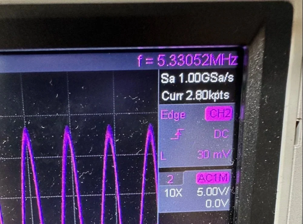
A little backstory here is kinda needed, you see the Ten Tec Scout 555 has become one of my favorite radios for POTA operations and I even find myself setting one up in the shack to tinker with from time to time. I own 3 Scouts and 2 Argos at the time of this writing if that tells you anything. I don’t know if it is the simple elegance of the radio or the fact that it can operate on almost all of the HF bands in such a small form factor, but I love it. Well there are a few things for sure that draw me to this radio like the fact that these radios have the now infamous Ten Tec full QSK (full break in) keying. This keying works flawlessly too by the way. Another reason for such love for these radios is the amazing receive they have even for such a compromise design. With headphones (or even those little earbuds), it is pretty easy to hear stations in the edge of the noise floor and make contact with them.
Well, if you noticed I said… almost… all the HF bands… This is because we have been granted, by the IARU, some space in the 60 meter band as secondary users.
Some of this band space is open to use with power levels up to 100 watts too. (There has been a recent change that modifies the allocation to allow a bandwidth section that is non-channelized but limits the power to 9.5 watts ERP so play in this area carefully. Basically this new region is a QRP only region for now.) Aside from that though, the Ten Tec Scout 555 can operate quite legally in the other 4 sections… or it could if… there was a 60 meter band module… You see this 60 meter band allocation happened after the Scout 555 production run had ended, so Ten Tec never made a factory band module for the 60 meter band that I am aware of.
I started this journey by digging through the owners manual for the Scout as Ten Tec always shipped complete schematic diagrams with their radios. Sometimes there would be missing insignificant data, but you could trouble shoot the radio just fine with them. Once the radio diagrams were located, I started looking at how the band modules made it change bands.This turned out to really be quite simple but I was missing one or two critical values. You see the Ten Tec Scout 555 band modules have a crystal in them and the frequency on the crystal didn’t make sense…at first.
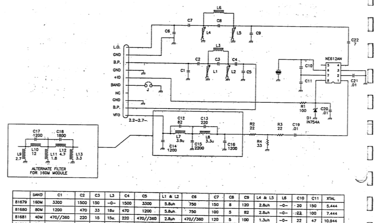
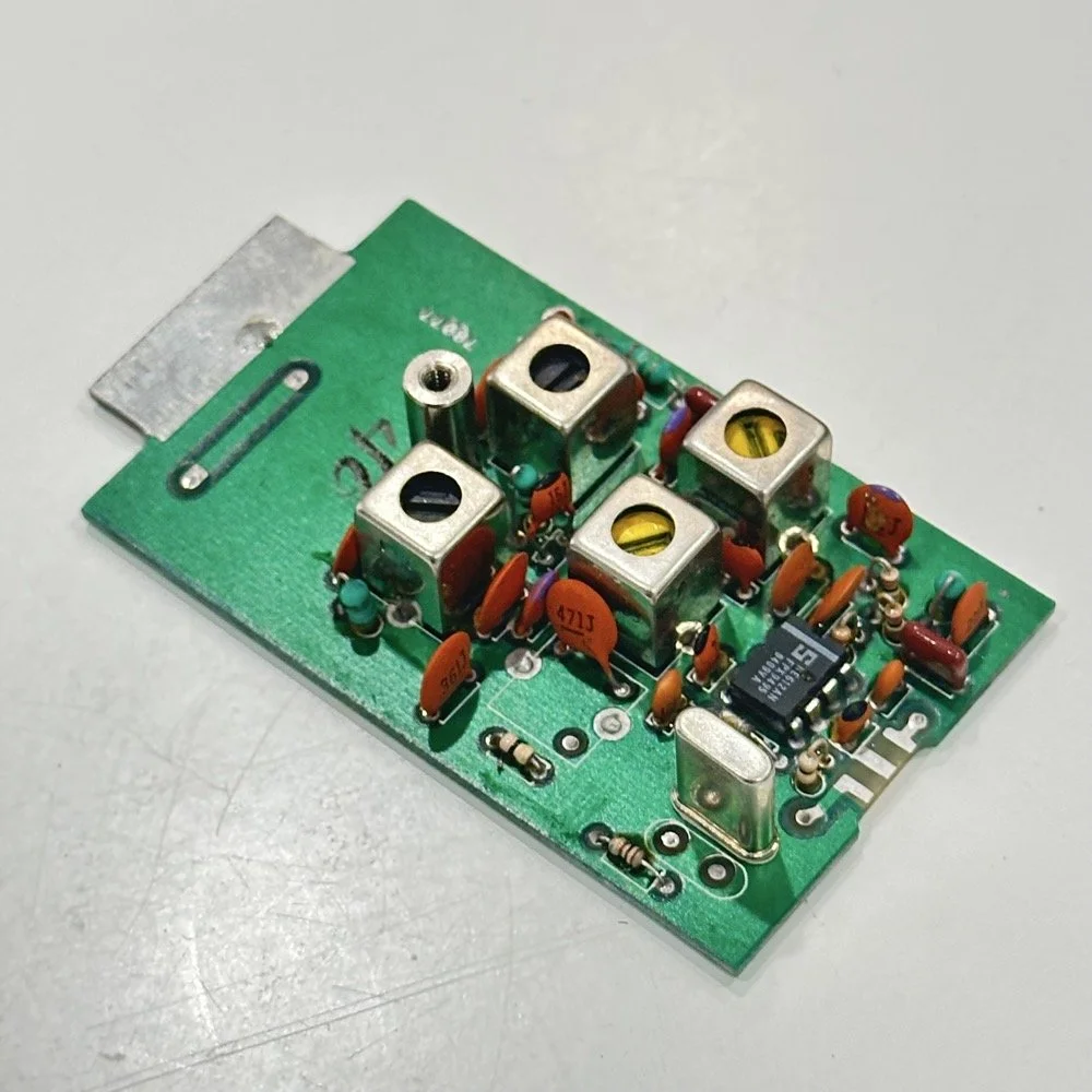
Above is the schematic and a photo of the board that goes with it showing the crystal that I couldn’t understand. This is what tells the radio what band it is on. Looks pretty straight forward at a glance, doesn’t it? Well look at that XTAL value at the end of the chart for 80 meters. Yeah, it takes a 7.444 mhz XTAL to get to the 80 meter band. So I figure the PTO is something like 3.0 mhz so it can get the first negative harmonic when mixed or something like that…nope…turns out I was totally wrong…
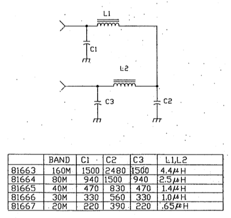
This is the other half of the band module. A classic low pass LC filter and that’s all. This is the output filter that the 50 power amp sends the RF to before it goes to the antenna. Below is what this part of the module looks like. These inductors and capacitors are shielded as they are delivering and filtering considerable power and could interfere with the small voltage levels on the other board that sits right beside it if they were not in the “can” or otherwise known as a ground shield. I don’t know why there is a hole in the shielding either as there is no adjustable parts inside the “can”. I chose this particular 80 meter band module for another reason as well. I have been inside this filter circuit before. When I acquired this module, the fellow I got it from told me it was dead and gave it to me. Turned out to be a broken lead on one of the inductors in this can. It took me a while to desolder this monstrosity to be able to access the parts inside of it. But persistence paid off as I was able to get it repaired and back in operation. I took a lead cut from a transistor and soldered it to the wire on the inductor and simply re-soldered it to the board and it came right back to life. So if you have a module that just stops transmitting all together, I recommend you pull the lid here and look at the inductors to see if one is broken free from the board, that might be all that is wrong with it. I also hot glued the toroids in place to help prevent this from happening again. Anyway, back to the project at hand…
I also looked inside several band modules to see what the differences were and I found some interesting things when I did. For starters, the 10 and 12 meter band modules both use the same circuit boards. They just leave out the second crystal and the switch parts for the second crystal and put a crystal in it for the 12 meter band only when configured for 12 meters. I guess, to be fair, I should have also figured out how the PTO worked as well then I could have figured out the reason for the odd crystal values, but here we are…
Another thing I found was that the engineers at Ten Tec used whatever circuit board blanks that they had on hand to build the band modules apparently. I say this because I found 10m circuit boards (the ones meant for two crystals and the switch) fleshed out with parts to make them into 40 m band modules. (Like the one in the photo above) They apparently just used whichever ones they had on hand at the time. Needless to say, what I thought was going to be simple was starting to turn into a pretty major endeavor.
You see it was starting to look pretty daunting since I didn’t understand what the reason for the odd frequency crystal was and that there were 4 tuned filters in each band module. Also the crystal value just didn’t make sense on the surface. The values were all over the place. I was about to throw in the towel calling it just too complicated, even though the parts count in a band module is really low…till I found two things. One was I looked up what the “555 timer” on the board actually was (Here is a hint, it aint no timer) and the other was NA5N’s website.
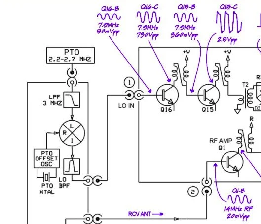
Excerpt from NA5N’s website showing the level of detail these drawings contain.
NA5N’s Scout 555 page is a figurative gold mine of information with just plain cash money piled on top of it, (just to drive this point home take a look at the piece above I grabbed for reference). I can not thank him enough for this information as without it I would not have been able to get this project working as quickly as I did. He also has some really interesting mods he has done to his own radio as well. If you want to perform his mods on your Scout, he gives you detailed information on what is done and literally how to do it…step by step almost. The greatest part of his page though is his info graphics he has built and placed there. These graphics show all sorts of information that the radio schematics leave out.
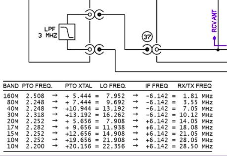
This and MUCH more is available on the NA5N website.
Things like the frequency path (pictured above) through the radio in a chart so you can understand how the engineers at Ten Tec arrived at each band frequency with these plug in modules and a PTO. Complete with oscilloscope test point and what you should be seeing at these points! Like I said, a gold mine buried in cash money…
Based on his chart I went through the band module and looked at the filters for the various circuits and decided (more like assumed based on the values of the parts) that I could simply re-tune an 80 meter module and “push” it up to 5.3305 mhz easily enough and without too much fuss…nothing could have been further from the truth.
So I start tinkering with the filters and piping them through the nanoVNA into the s21 input so I can see the filter shape and all is well from what I can see. Turns out the low pass 80 meter band module filter cut off frequency was about 5.5 mhz or so to start the rolloff so the 60 meter band was still in the pass band! One down three to go! Next I figured out that the PTO is the same for every module since it is part of the radio and not in any of the modules so that filter also didn’t need any mods. This left two filters to re-tune, just so happens it is the two with the adjustable inductors in them. So I start with the LO BPF (Local Oscillator Band Pass Filter) that filters the signal passing through the radio from the antenna. Why they call it the same thing as the LO BPF that is in the output of the mixer chip is beyond me, but here we are… This didn’t go well as I was not able to get enough adjustment out of the inductor slugs to get the passband up to 5.350 mhz, shoot I couldn’t get it to tune up past 4.5mhz if memory serves me. It was far enough that I couldn’t get it work so I looked at what I had and decided to wind some air-core inductors to a lower value and see what I could do like that.
Well, to be honest, I don’t know how I was so successful here. Maybe it was the sheer audacity in the fact that I was woefully unskilled in building filters for HF or the mind boggling lack of knowledge of how filters work and how to make them, but I got it almost perfect on the first try! I made a couple different inductors by winding magnet wire on a 1/4-28 bolt (that’s a little over a 6mm bolt for the rest of the world) and the threads made getting good tight coil layers easy. I borrowed my friend’s LCR meter and measured them and blissfully declared them good to go at 2.0uH each. Did I mention this is a budget LCR meter and I have no way of knowing what the level of calibration is for this part of the meter? I also learned later that I can measure my inductors with a signal generator and a oscilloscope. Guess who now owns a signal generator as well as an oscilloscope...
Once wound and “measured” in the board they went! I then tinkered with the capacitors till the pass-band looked close to what I thought it should look like. (I had also learned from the wonderful world of youtube that I should see less than 1dB of loss in the pass-band and the 3dB cutoff point is where the filter technically is measured..typically.) As I mention in a bit, I used the wrong kind of capacitors (the little blue ones) to start with, although the module did work like this, I updated it with NPO capacitors ultimately as well.
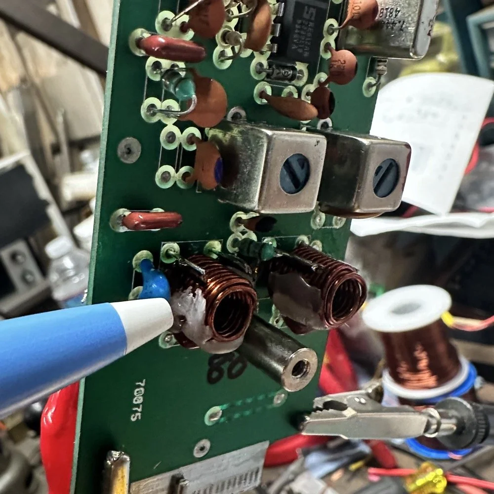
I went down a long path of learning on this project, if you haven’t already noticed from the inserted comments in the story. I have very little formal training in Electrical Engineering, you see I went to a two year trade school back in the 1980s and basically got the “intro to electronics” that EE’s would get before learning things like matching the impedance of the filter to the next stage and to use temperature stabilized capacitors in RF filters so they don’t move the pass-band around when they get warm. NPO capacitors have become my best friends here…lol. A hint for my peeps who also didn’t study RF in college, look at the circuit board above that has the crystal on it. You will see the little capacitors on that board and some have little painted tops on them. This indicates NPO capacitors when the letter designation will not fit. I have now purchased a lifetime supply of these caps off of eBay…haha.
Anyway, now the pre-amp band-pass filter was functioning like it should. One to go…
Tune in for part two where we get into the problems I had to solve to get this module working and how well it works now that I have figured out my mistakes.
Continue reading the series:
- Part 1: Initial Conversion and Filter Design
- Part 2: Crystal Selection and Mixer Circuits
You can help support this website by using these Amazon Affiliate Links:
QRP/Portable Radios:
Antennas & Tuning:
CW Equipment:
Power & Accessories:
Organization & Transport:
BONUS ITEMS
73
WK4DS - David
![Multi-Mode POTA Activation: Penntek TR-35 CW & HT FM on 4 Bands at Sitton Gulch [K-2169]](https://images.squarespace-cdn.com/content/v1/5d17806ce65eba00011667cb/19188a17-7511-4f72-9997-c058e4aec3ea/IMG_7809.jpg)
Multi-Mode POTA Activation: Penntek TR-35 CW & HT FM on 4 Bands at Sitton Gulch [K-2169]
I made over 20 contacts in short order with the Penntek TR-35 radio in bare bones configuration today so that I could get it up and running faster. This radio is a gem to use like this with a simple set of headphones and I dont mind operating like this one bit. This actually makes it easier for me to hear the calls to be honest about it.
Today I wanted to work an activation but I also wanted to grab a couple more bands as well so I hatched a plan to grab some VHF and UHF bands on FM Simplex if my friend KG4WBI happened to be home.
Today was also cold, which you can not see in the photos, but trust me…it was pretty cold. Since it was so cold, I opted to operate from inside the truck and setup a hamstick on 20 meters (I was being lazy today and didn’t explore the other bands) as I wanted to get the activation completed in about an hour since I had to be in Chattanooga for lunch. The 20 meter band will usually guarantee that to happen for me on CW, so I started there.
I noted in the below photo that the one shorter radial had to be pulled taught and the this is where the counter weight was at that held it in position. This is of little consequence other than I am starting to wonder how much capacitance I am getting at the end of the radial from these stainless steel weights at the end of each radial? They are not connected physically to the conductor but are probably capacitive to it through the wire insulation. I used speaker wire for these radials and it has worked really well over the years. I think the next deployment is going to have a smith chart plot where I take the weight off and just tie it off to a stake of some sort. Maybe a chop stick since there is really no tension on these radials. That way I can see just how much capacitance these weights are adding and I can also see if it is helping or hindering performance.


In these two photos I tried to capture something that was of interest to me, today the 20 meter hamstick seemed to tune much better with one of the radials drooped down to the ground and not outstretched like the other one. The one that is pulled taught is the one that is shorter due to the wire breaking over the years and me twisting it back together by hand so I could use it. With this setup, the nanoVNA said the SWR plot was 1.1:1 and it sounded like it on the air! The stations were booming in! I was getting reports back from many stations of 599 with my little Penntek TR-35 radio too!

Once I got everything setup and tuned, I hopped on 20 meters CW to see what I could scare up. Well that turned out to be a great idea as i quickly had a good pileup going and had great fun working through it.
I made over 20 contacts in short order with the Penntek TR-35 radio in bare bones configuration today so that I could get it up and running faster. This radio is a gem to use like this with a simple set of headphones and I dont mind operating like this one bit. This actually makes it easier for me to hear the calls to be honest about it.
Being cold like it was today, I decided to operate in the truck so I could stay warm and could feel the key in my hand unlike the trip to DeSoto Falls state park recently…lol.

Once I was finished with activating on 20 meters CW, I thought I would try to work my friend KG4WBI who lives a few miles away from this location. I knew he had the ability to work me on all three VHF and UHF bands that my HT can transmit on, so I hopped on my trusty HT and gave him a yell on his repeater the KG4WBI/R 1.25meter machine.
He was, in fact, home and he was more than happy to hop on simplex for a few peer to peer FM QSOs so I could add a few more contacts to the log as well as a couple of new bands as well. In the above photo, I had walked across the parking lot to the building in the background that you can see in the photo above. It is behind the white truck in the antenna photo. This spot gets most of the stuff out of the way so I had the best chance at a contact with a HT. Turns out it worked great on 2 meter and 1.25 meter, but 70cm just would not work from here with all the trees in between us. So I gave up on that band and went back to the truck to pack up and head on to a lunch date I needed to be at.
On my way to the truck I had an epiphany. I could just drive down to the lower lot and walk out to the northern most viewpoint on the canyon edge and it should give me clear enough line of sight to make the contact! I would still be WELL within the park bounds and it was the same UTC day. So I packed up the HF gear and headed down to the canyon rim. Called Roger on the repeater again and informed him of my plan, which he agreed to merrily. So we switched over to simplex again and I put in the 70cm call frequency then called Roger’s callsign and he immediately came back with a 59 signal report! Success!!! 4 bands again!!! Woohoo!
The lower photo is me down by the canyon rim where I made the 70cm contact. Don’t I look happy… lol.

I wanted to share this activation with everyone as it highlights a part of POTA that alot of people overlook. Well, actually two parts… one is that it extends to ALL hambands and the second is that you can absolutely use your HT to make short range contacts on FM and they count just as much as those great distance HF contacts. Dont discount 2 meter SSB either. There is plenty of people there too.
Anyway, it was a great day for radio and I appreciate yall coming along for the ride.
You can help support this website by using these Amazon Affiliate Links:
QRP/Portable Radios:
Antennas & Tuning:
CW Equipment:
Power & Accessories:
Organization & Transport:
BONUS ITEMS

Elecraft T1 Antenna Tuner Review: Field Testing with 41' EFHW at DeSoto State Park POTA
I wanted to put the Elecraft T1 automatic antenna tuner in “remote” location mode to experiment a little with it. This meant placing it at the antenna feed point (that is the BNC to Banana plug adapter you see below. I simply tied the 41’ wire to the red and the 9’ counter poise wire to the black and then ran a COAX from ABR Industries to the radio. I like this coax as it has the common mode choke preinstalled so I dont have to add my other one to the system.
I finally bit the bullet and bought me one of these amazing little tuners! The Elecraft T1 automatic antenna tuner is a marvel of modern engineering and I dont know why I waited so long to get one. I took it with me today to test out and see if it would do what I needed…

Today saw me at DeSoto State Park which is located atop Lookout mountain in the NE corner of Alabama. This park is beautiful an was built during the Great Depression by the CCC (Civilian Conservation Corps) and most of that stone work is still there today. The photo below shows the original entrance to the park and the stone work at the entrance is still there. Today, you enter the park from a different road for most stuff but this road it still open to use and I love going this way just to see these vintage masonry works.
If you are interested in learning more about this park just follow this link to the State park website.


Once on location, I set out to put a 41’ random wire into the nearest tree to the truck so I could tune it to all four bands in the Penntek TR35 radio if I wanted to and kept me from having to dig out the hamsticks and all that hardware. I tied the lower support rope to the door handle of the truck them threw the line over the limb I am pointing to in the above photo and got almost all of the antenna in the air before getting into the branches. It was not shorted to anything, but it was in the branches so I was glad to have a tuner handy to dial it in.
I wanted to put the Elecraft T1 automatic antenna tuner in “remote” location mode to experiment a little with it. This meant placing it at the antenna feed point (that is the BNC to Banana plug adapter you see below. I simply tied the 41’ wire to the red and the 9’ counter poise wire to the black and then ran a COAX from ABR Industries to the radio. I like this coax as it has the common mode choke preinstalled so I dont have to add my other one to the system. This cleaned up the install greatly, but did create one little problem… I had not made up a remote “tune” switch yet so I had to get creative with the tuning process. Since the whole thing was on the truck bed cover, I was able to get the CW key over to the tuner so I could key the transmitter and hit the tune button at the same time.
I already have a plan on making a cable that will allow me to tune the antenna remote from the radio in the future.I will share that once I get it put together, but rest assured that it wont be a long time…lol.

I setup the whole shebang today with my homebrew S meter and the auxiliary system box I made up for the Penntek. You dont know how hard it is to get the display to show the whole frequency during the daytime with an iPhone. HaHa. The refresh rate and the shutter speed are so different that you have to time it to get the whole number to show up. You can see the Elecraft T1 in the background where I had it tied to the antenna. You can also see how I have just slid the key over to tune it for the next band change as well. If you will simply plug the paddle into the straight key input, one of the paddles will act like a straight key allowing you the key the transmitter for tuning purposes.
To be honest, I have used this input in the past when I was trying to use a cheap eBay paddle I had bought to test out for travel. One arm literally broke off and I laid it on it’s side and used the other paddle like a straight key to finish the activation. You do what you gotta do I guess…
Another thing is that it finally turned off cold here. it took it till mid November to find us, but winter is here now and it was kind of all at once too. Like last week it was in the high 60s and low 70s and now it is in the 20s and 30s all day. The cloak in the sun is wonderful though and will keep me warm just fine for things like this. This cloak is make of wool so it is incredibly warm and can quickly become too much if I am active much at all.


Today also saw the deployment of the Gemini travel key as the Penntek has two keyer memories and I dont need the PicoKeyer to work this radio. I could still use the PicoKeyer if I just used the straight key input, but the internal memories do all I need and I like have them in the radio. It just makes the whole system smaller an more compact.


I know that I failed to number the contacts, but this is because I had such a strong run on 20 meters and didn’t have time to write down the numbers. It is over 40 contacts and that is a great day for me in the field! Once I moved to 17 meters I could have wrote them in, but at this point I didn’t see any reason to start so I just omitted them this time. It didn’t matter as I still have a great time and the hunters seemed to enjoy the day too. Thanks for following along and a I hope to see you again soon!
You can help support this website by using these Amazon Affiliate Links:
QRP/Portable Radios:
Antennas & Tuning:
CW Equipment:
Power & Accessories:
Organization & Transport:
BONUS ITEMS
72
WK4DS
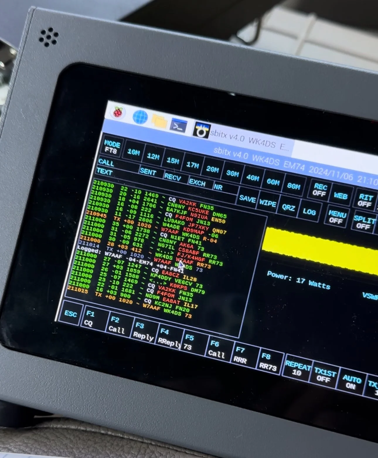
sBitx V2/V3 CW Problems: Why I Switched to Ten-Tec and Penntek for POTA Operations
When I first got this radio, I found it had some keying problems on CW but I just adapted to them and used it anyway. These problems are in how the software monitors the CW circuit and keys the radio and such. Turns out that as the radio heats up, the problem tends to get worse causing me to have to slow down the keyer to be able to send accurate code. Even with these tactics, I still send many mistakes towards the end of an activation due to the lag in the keyer.
I have an interesting relationship with this radio…

When I first got this radio, I found it had some keying problems on CW but I just adapted to them and used it anyway. These problems are in how the software monitors the CW circuit and keys the radio and such. Turns out that as the radio heats up, the problem tends to get worse causing me to have to slow down the keyer to be able to send accurate code. Even with these tactics, I still send many mistakes towards the end of an activation due to the lag in the keyer.

The reason I currently dont use it for SSB is the audio is terrible and I need to trouble shoot that on the bench to see what is going on there. At first it had a weak microphone element so I made a preamp to correct for this but it still doesn’t seem to work all thatwell. Based on all this, I have not used SSB. (I do plan to revisit the SSB circuit to see if I can get it right)
As I also own several portable Ten Tec and Penntek radios that work wonderfully for SSB and CW, I threw in the towel and just started carrying one of those as well as the sBitx. It doesn’t take long to change out the radios since they are so small and light and I really like the break in on Ten Tec radios (the Penntek has wonderful break in too). Another huge plus is that the filtering on the Ten Tec radios is much better than the sbitx in my opinion. Now to be fair, the sBitx filtering is good, but the Ten Tec radios are just better. The Penntek TR-35 suffers the same problems that the sBitx suffers from. Strong, nearby stations will dull the receiver sensitivity.

What I have found that helps in the scenarios is to simply move. There is nothing an overloaded front end can do to help this problem. I do like the features that are available in CW on the sBitx though. Things like the memories and how easy they are to employ is awesome. Another thing is the waterfall is real nice that runs right alongside the CW decoder which has helped me a couple of times. I dont watch the decoder much, but it is nice to be able to see it match what I copied at times for call signs and such. Another great thing about the sBitx is the touchscreen. Not needing buttons is real nice. The only part of the experience that is honestly lacking in CW is the keying problem. Once someone solves this problem, this will be a game changer for a radio. I am still experimenting with different cooling solutions to keep the machine cooler to see if I can get the keyer to work better.

As you can see, this machine makes for a great FT8 field radio. The lack of a need for an external computer is a huge benefit when it comes to this. I just wished the dev team could sort of the CW keying problem this radio has that makes it less than ideal for this application at this time. One thing I plan to do soon is to set it up and see how running QRP power only helps alleviate the heat problem by not running 20 watts on 15 meters and building up the extra heat. This may solve most of my problems but the radio is designed for more transmitter power so I want to access that power.. Another option is to use a keyboard to send the code as it generates the code internally in software instead of polling the IO architecture to get the keying input. This is fun to me too but a nice key is also fun to use. So till the dev team does come up with a solve for the CW keying problem, I will relegate this radio to keyboard CW and FT8 (and maybe even SSB once I address the audio problem again)… But the main reason I wanted the radio to start with was the built in FT8 function that it has, so in that regard I have a great radio that I love to deploy!
If you are considering getting one of these radios, just be aware that it is far from perfect and it is literally made for experimentation. As long as you keep your expectations in reasonable bounds, this radio can be a lot of fun.
You can help support this website by using these Amazon Affiliate Links:
QRP/Portable Radios:
Antennas & Tuning:
CW Equipment:
Power & Accessories:
Organization & Transport:
BONUS ITEMS

Multi-Band POTA Strategy: Ten-Tec Scout 555 + sBitx FT8 on 15m/17m/20m/40m
The location is all too familiar, but I set out to do a sort of special operation today. I wanted to complete a POTA activation using two radios, 3 modes and 4 bands in one sitting. This doesn’t sound like a tall order but since I am operating inside the truck cab, this does involve a little logistics to not just have stuff piled everywhere while I am operating. As you will see in the photos below, I still ran into this problem somewhat, but it was manageable.
Today was a fun day…

The location is all too familiar, but I set out to do a sort of special operation today. I wanted to complete a POTA activation using two radios, 3 modes and 4 bands in one sitting. This doesn’t sound like a tall order but since I am operating inside the truck cab, this does involve a little logistics to not just have stuff piled everywhere while I am operating. As you will see in the photos below, I still ran into this problem somewhat, but it was manageable.
I setup at the disc golf parking lot again, but this time there were quite a few people there and some of them actually quizzed me about what I was doing. One gentleman, Jerry as noted in my log, actually chatted for a good bit about how he has been looking to get into ham radio but the Atlanta area is kinda tough on locating local hams for some reason. I gave him a card and told him to email me and I would give him as much info on it as I could find to get him on the right path…
As you can see in the photos, I set up ham sticks and this time I started on 40 meters FT8. I wanted to get the FT8 portion of my “sprint” if sorts out of the way first as the other two modes were going to be on the Ten Tec Scout 555. I had recently activated with it and it was acting up with chirping on CW and reports of RF noise on my audio on SSB. I attributed this to poor connection of the 20 meter band module as it was fine on 15 meters. Armed with this knowledge, before I left out for the park, I took the radio to the shop and use the Deoxit for gold contacts and a tooth brush to clean the contacts on the band modules. I even wetted one module pretty good and used it to “clean the contacts in the radio by plugging and unplgging the module a bunch of times.
This improvised procedure worked as I got good reports and the CW ran flawlessly as you will see later. Deoxit is magical stuff, if you dont have any, it is work your investment to grab a small can of it.


I really enjoy using this radio for my FT8 operating and with the upgraded finals and RF deck, it runs flawlessly now with SWRs in the 2:1 and even slightly higher range without problem. Today saw SWR levels on transmit of about 1.7:1 and it happily skipped right along making several contacts in a row at one point.
After completing 6 QSOs on FT8 I figured it was time to get the Ten Tec Scout 555 out of the case and see what I could scare up on CW.
The 40m Ham stick that I have must have a really high Q as it is very narrow banded. So I have it tuned for the CW portion of the band and the SWR in the SSB area can be quite bad at times. For this reason, I chose not to hunt any SSB contacts on 40 meters today. Once on CW (this was about 1/2 hour later as this is when I talked to Jerry) the band must have been closing or the band noise was getting so bad that I could not hear many stations. I was able to work Alabama and Tennessee before the call signs faded into the noise. That is something you will learn pretty quick about HF radio propagation, if you want to work closer in stations, use the lower bands, but if you want to reach the west coast from Georgia on a ham stick, use the higher bands like 15 and 20 meters. When 10 meters is open I have worked other continents with ease… Don’t discount those higher bands, they are truly magical.

In the above photo I have the CW key and keyer staged but not connected. The mouse is actually driving the FT8 machine and makes working FT8 so much easier to be honest.

In these two photos you can see what you have to work on constantly. The above photo shows the cable that came with my Ten Tec Scout 555 when I bought it. This is a common issue you will find with home shop made cables. These were stripped back way too far and as I used the cable, the conductors started breaking and I was beginning to worry about blowing fuses.
I happen to own a tool that is designed to remove these pins from the connector, so I am able to dismantle this connector properly. I dismantled it, then took it apart and cleaned it up, properly stripped and re-soldered the pins, then put heat shrink tubing on it all to insulated and protect it better. Now I am not so worried about it either shorting and melting the wire or blowing the fuses and shutting down the activation over something as simple as a cable…


Once I finished on 40 meters and had two modes in the bag on one band, I switched over to 15 meters CW to see what was happening there. There was a contest going on so it was a little crowded and I didn’t understand the exchange so I didn’t jump into the contest, but rather setup on a clear spot and calledCQ and worked a couple of stations there, one station of which is DX!!!
At this point. I got a phone call from KG4WBI about a completely unrelated matter, which we discussed and I told him to fire up his HF rig and we would see if ground wave would make the trip to his house from the park so I could get Georgia in the log as well as a 2nd mode on 15 meters! Well, it worked just fine and we had a great QSO on 15 meters SSB before he had to sign off and go run errands. So having confidence that SSB was going to work better I started calling CQ on SSB.
I got literally zero replies to my calls… so I went hunting instead. I found two more ops that could hear me and I was able to bag a couple more QSOs and these were Park to Park contacts to boot!


These three photo show me installing the band module into the Ten Tec Scout 555 transceiver. It really is that simple to change bands on this radio. Now to be fair, this is not as simple as just turning a knob, but it really isn’t that bad.
To remove the module you pull out the bottom of the little lever on the front of the module and it will pop out enough to be able to slip it out, then you grab a different one off of the pile and stick it back in the slot in the radio. Push it to seat it and then your ready to go.
At this point, I switched over to 20 meters and since the PTO (notice it is not a VFO) was still up in the SSB area, I decided to see if I could hunt some contacts with that mode. I landed one contact in SSB on 20 meters and was happy to get them in the log.
After working the one lonely SSB contact on 20 meters, I decided to give CW a try as well… Remember me mentioning a contest? Well, it was here too. It was going strong as well and because of this I was only able to work one contact on CW as well. If nothing else it netted me another band!

My last stop of the day was 17 meters. The 17 meter band is a WARC band and therefore it is off limits to contesting. Now, to be fair, POTA has been called contesting of sorts, but as of right now it is not considered a contest but is more in the spirit of something similar to a rare DX station activating on the same band and developing a huge pileup there. So I proceeded to hunt me an empty spot (18.078mhz) and started calling CQ.
This is when things literally took off! I netted a whole page of contacts in about a 1/2 hour span of time! What a day! 4th band in the books and I was stoked!!! 17 meters must have been where all the POTA ops had went due to the contest and I didn’t get the memo…lol. The Scout worked flawlessly after the cleaning and I cant be happier now with the old girl.

One of the great things about 17 meters is the propagation is really anybodys call. I worked Hungary at one point as well as California, Alaska and Idaho, then there is a ton of east coast stations too, it was everywhere today on 17 meters. Ham radio is so cool…

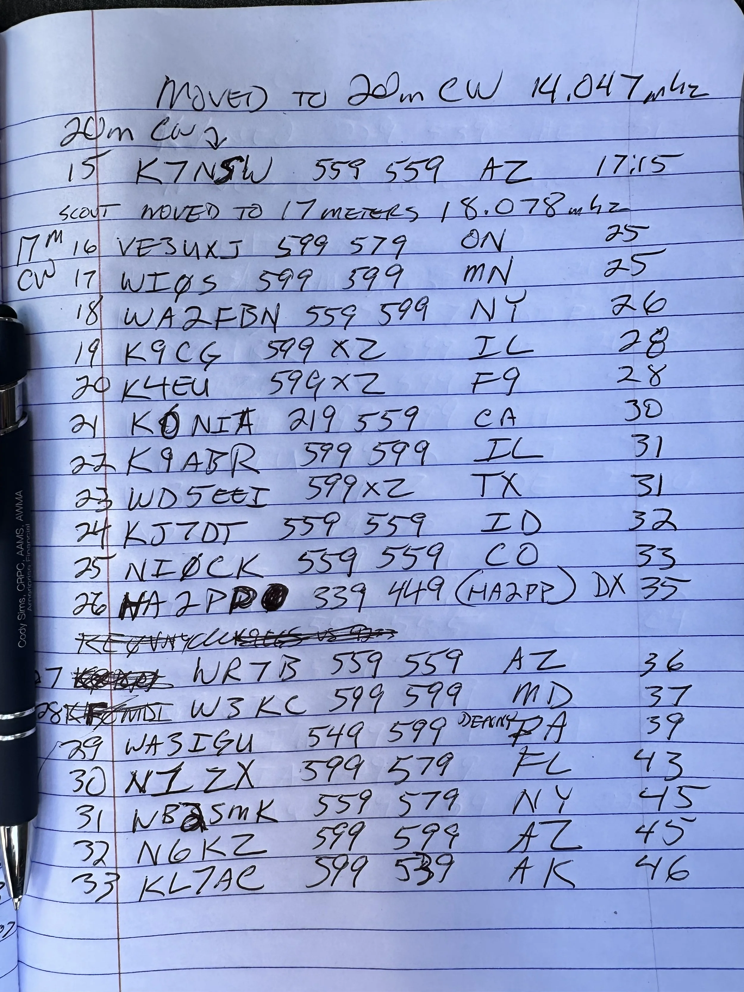

Before closing today I wanted to mention that Aaron KV9L and I have a youtube channel and we just hit 2000 subscribers (as of this writing)! If you are into ham radio and watching videos about it, then we would love for you to come over! I am currently doing a series of short form videos that are teaching CW one letter per day. There is no limit to the number ofd times you can watch them so I am hoping these become long term training aids for people.
Once I get the letters, numbers and punctuation done, I am going to start doing words next. After words will come sentences so we will see how it goes. Anyway, I just wanted to thank the 2000 people that made us as successful as we are!
You can help support this website by using these Amazon Affiliate Links:
QRP/Portable Radios:
Antennas & Tuning:
CW Equipment:
Power & Accessories:
Organization & Transport:
BONUS ITEMS
73
David -WK4DS
![Ten-Tec Scout 555 POTA: 74 CW Contacts at Raccoon Creek WMA [US-9875]](https://images.squarespace-cdn.com/content/v1/5d17806ce65eba00011667cb/fe9e1368-6e59-44e9-9c7e-d01d02e14fe8/IMG_7569.jpg)
Ten-Tec Scout 555 POTA: 74 CW Contacts at Raccoon Creek WMA [US-9875]
As you can see from the QSO map above, the bands were alive and well on this day from Raccoon Creek WMA (US-9875). The calls just kept coming in and I finally had to got QRT, with people still calling, and pack up as I had to meet the wife for a dinner date! I normally clear the little pile up I will draw in and then I can simply power down. I really felt bad about having to shut down with stations still calling me. I now know what those rare DX station feel like… It is surreal to experience that to be honest… especially from Alabama.
Today got so fast paced that I forgot how to do CW properly! Let me explain…
As you can see from the QSO map above, the bands were alive and well on this day from Raccoon Creek WMA (US-9875). The calls just kept coming in and I finally had to got QRT, with people still calling, and pack up as I had to meet the wife for a dinner date! I normally clear the little pile up I will draw in and then I can simply power down. I really felt bad about having to shut down with stations still calling me. I now know what those rare DX station feel like… It is surreal to experience that to be honest… especially from Alabama.
You see, today I activated US-9875 Raccoon Creek WMA and I went at a different time of day. I wanted to spend several hours here today as I dont get over to the area often and I wanted to try to get as many contacts as I could in the afternoon. My goal was 60 QSOs today which is way more than I usually worry about, but like I said, this park is a solid 40 minutes in one direction and I dont go this way too often so I wanted to “make it count” if you know what i mean.
I rolled into the WMA at about 14:30 local time and set out to build the radio down by the Tennessee river. This is a small parking lot at the end of one of the gravel roads into the WMA and a lot of locals come to this spot to fish in the river from the shore. Did I mention it started raining right after I got the antenna setup and I got into the truck? Well, let me tell you, the rain set in and it didnt stop the whole time. I even broke down the antenna and stuff out in the rain today!!!


The above photo shows what the station looks like right before I plug all that stuff in and turn the power on. Everything I need to get on the air is in that pile for both SSB as well as CW. To be fair, I can get by without the Picokeyer and the 1/8 mono to 1/8 mono cable and I could simple plug the paddle right into the radio and it would work just fine. So there is really excess here above what is absolutely needed.
I did get the nanoVNA out and look at the antenna to make sure the rain didn’t do something to it like push it out of band due to the conductivity of the wet earth or what ever. Turns out it was just fine… It was a little low with the water on everything but the null was really close to the bottom of the 15 meter band edge so I used it and didnt worry about it. If you will notice, it was only 1.233:1 SWR at the band edge so it was plenty happy and we never checked it again after this on 15 meters. When I switched to 20 meters, the SWR had moved up to about 1.8:1 or maybe it was at 2:1 but I ran it and as you can see in the log, that didn’t seem to matter at all.

I setup shop on 15 meters SSB for a change and wanted to see what I could get before 15 faded out, but I noticed almost immediately that the ALC light wasn’t coming on at all when I would transmit audio. This lamp should just blink on the energy peaks but it wasn’t coming on at all. I messed with the mic gain and nothing. I did notice that I could wiggle the cord at the plug and it would make all sorts of stuff happen. This pointed me to the connector being faulty somehow but workable to some degree.
I made a few contacts with it like this and basically yelling at the radio would barely get the ALC to illuminate. I asked the last person for a report and they told me the audio was muffled and weak. Armed with all this knowledge, I decided to open the connector and see if a wire was broken. Well, they were not broken…but they were also not connected either. There were two cold solder joints from the factory…figures. I got a pretty decent photo of the green wire in the below photo. Well…that shuts down the SSB portion of this activation so onto 15 meters CW!

The 15 meter band has two things that make it unique. It is quieter than the lower bands for me and the “skip distance” is MUCH further with mobile, or improvised antennas. I didn’t make many CW contacts on 15 but check out the locations! Washington state is pretty common for me on 15 meters, in fact the entirety of the western United States is easier for me to work on 15 meters during the day. But a lot of people apparently don’t know this so lots of times the band will be open but there wont be anyone on it. Case in point today, I worked 4 ops in 11 minutes of calling CQ.
After vacuuming the bands of CW ops, I moved to FT8 to see what was happening and this is my “yardstick” of how open the band is. Turns out it was REALLY open! 15 meters FT8 netted a nice dozen contacts and got me almost half way to my original goal of 60 QSOs! This didn’t take long either and just goes to show that the higher bands are great if you will just go check them.

I had switched radios to use the sBitx V4 (I did the software upgrade and got some new features like the color coding of FT8 information you see below) You can also see that I was transmitting with 17 watts too. This is not precise, but it is close and I use it for my logbook notes.

After finishing on 15 meters I moved down to 20 meters to finish out the day. The sun was starting to set at this point and I knew 20 meters would serve me better at this point. after hunting W9XT, I set up shop on a clear frequency and started calling CQ, this is when things got a little crazy. I had a nice little pileup form pretty quick that took me about half an hour to clear, then nothing… It must be band fading at this point as the stations just vanished. I figured I would switch over to FT8 for a few minutes at this point too and see what I could get in that mode. I didn’t mention that I used the sBitx for CW at this point and to be honest, I dont think I will use it for CW seriously till there is a software change to make it work better. If you try to use it much past 18WPM it is like it fights you and induces mistakes for some reason. The people smarter than me in the email reflector seem to think is has to do with how the software scans the inputs on the radio, but I do know it will induce mistakes in your sending if you are not very attentive and send a very specific way. It will work if your careful and go about 18WPM max. I can use a keyboard to send CW but that really isnt all that much fun to be honest.
I struggled with FT8 today on 20 meters for some reason. The QSO could not complete to the 73 so it would not autolog the QSO. It would also not finish the exchange many times either. I could get it to send the signal report then they would send back and they would just get stuck in that step and never move past it. It got really frustrating towards the end, but I did manage to net some contacts here too.
At this point I had made 48 contacts which is a phenomenal day out for me, but I wanted 12 more to have that 60 that I started out my goal with! So at this point I move back down into the CW portion but this time on the Ten Tec Scout 555 instead since the CW mode on it works beautifully.


It took me a couple minutes to switch the radios out and to find a clear frequency and get started, but once I did, it didn’t take long to get a HUGE PILE UP going!!!! I got so excited during this part that I was racing the clock to see how many I could work before having to shut down the radio and go home as I was almost out of time. I started rushing the closing and it was here that I got sloppy with my CW. You see, I normally use QRP power levels for the most part, just the sBitx and the Ten Tec Scout are QRO by the rules and the sBitx is borderline to me. I will usually turn the power down to 5 watts or so anyway to preserve the finals in the radio but today I had the Scout and it is set at 50 watts and is not easily field adjusted from that power level.
As the pile up raged on, I got so lost in the process that I started sending 72 intermingled with contacts getting 73 instead and finally someone stopped me and asked why I am signing both modes and this is when it hit me. I had been running on autopilot about half the time just logging contacts and the muscle memory would just send the 72 and I would not even think about it. I would then called QRZ and get another call, rinse and repeat… Here is the next problem for me. My ragchew copy and my POTA copy are very different levels. He sent me the message at the speed I was working POTA contacts. Your brain will learn how to copy the formatted style exchanges without even thinking about it. I know that I am going to get a two letter state after the signal report and I can copy callsigns really well for some reason up to about 25 WPM, but send me a full sentence question and it breaks my brain. I cant copy half of it without writing it down. I can ragchew comfortably at 18 WPM max at this time, but if you ask me a question about my radio or something that isn’t part of the usual banter in a POTA contact and I am lost… I apologized for this mistake I had been making for probably 20 minutes without even realizing it and it was really close to when I had to leave anyway so I went ahead and called QRT to get the radio put away as it was raining really well at this point too…
To everyone that reads this that I didn’t get to work on this day, I am sorry to have to had shut down the rig and leave, I was having a wonderful time and wanted to stay longer!!!


The moral of this part of the story is dont get in such a hurry that you cause confusion with the hunters, take your time and be sure in what you are actually sending out over the airwaves.
On a brighter note, I got my 60! and 14 more!!! I dont know how long it has been since I got that many calls in the log in one day. Until next time I hope to work you on the air!
Read more Ten-Tec Scout 555 POTA activations:
- [Another Scout 555 POTA post]
You can help support this website by using these Amazon Affiliate Links:
QRP/Portable Radios:
Antennas & Tuning:
CW Equipment:
Power & Accessories:
Organization & Transport:
BONUS ITEMS
73
WK4DS - David