WK4DS Amateur Radio Blog
Search Posts
Finally got my sBitx V2 radio…so I went to a park!!!
Quick synopsis is I like it. Read on to see why.
When you see this radio, you think it is like one of the big name machines. It is not. It is actually so much more because of the nature of the project that it comes from.
The HF Signals sBitx V2 is an evolution in their radio designs and brings so much to the table that is cant be described in one blog post…well maybe…I can write as much as I want in one post…lol.

The TR-35’s magic is the lack of menus.
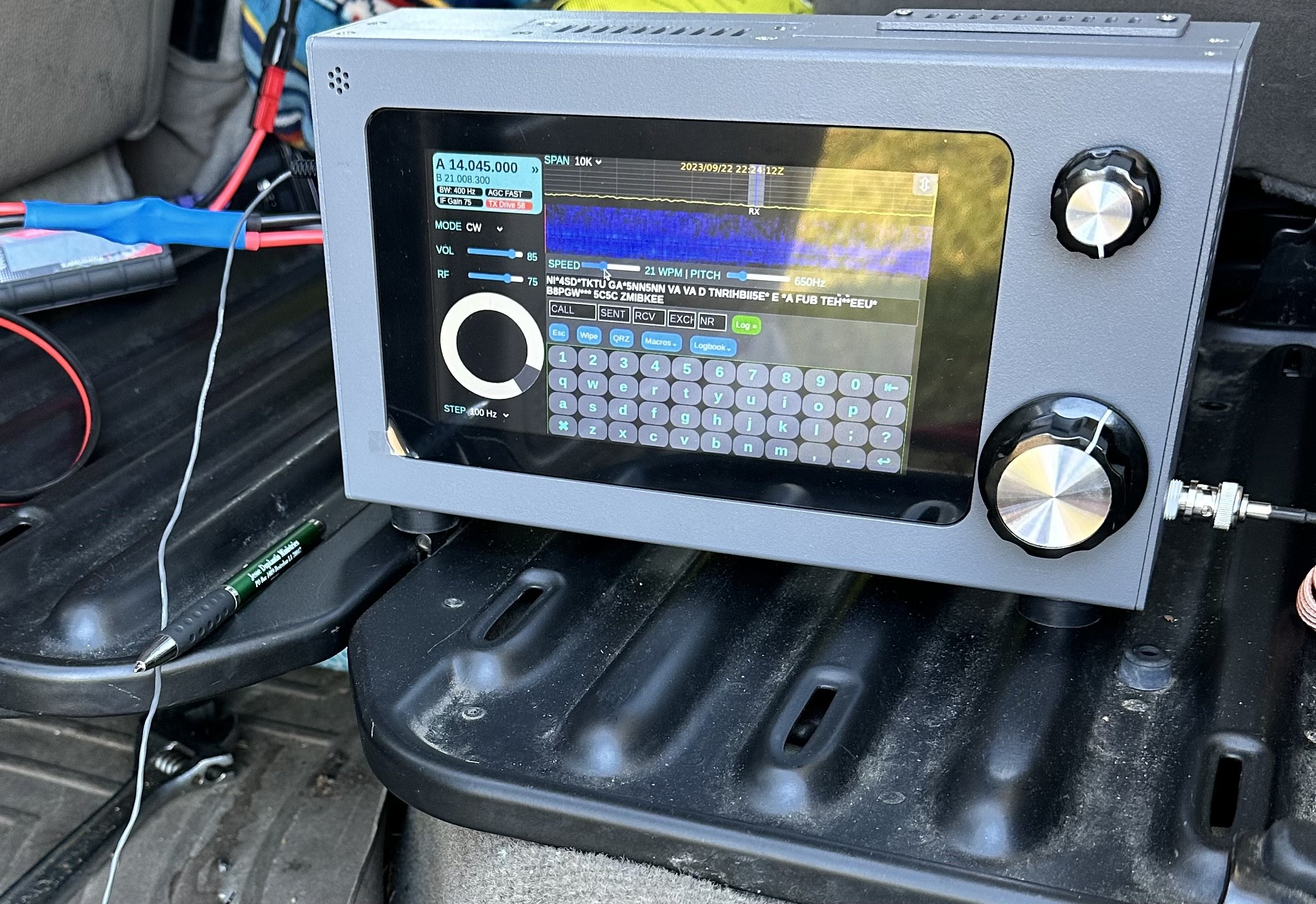
The first thing you notice it the lack of buttons or switches like my Penntek TR-35 has on it in the photo above. There are simply two knobs and a display and that is all you are greeted with at first glance.
Well this is a kind of sleight of hand trick as the display is actually a touch screen and almost all of the controls are driven from this display. In fact, what appears to be at AF Gain (volume) knob, is actually like the multi-function knob on my Ten Tec Omni 7 being selectable for an array of things it can control.
Both knobs are also push buttons and the smaller one defaults to volume control if pressed, but the larger (VFO) knob doesnt appear to do anything when pressed, I can not find anything in the literature describing it so it is there for tinkerers from what I gather. You see, this is an open source SDR, this menas you can download the source code and if you are savvy with coding, you can add features or modify how the radio works to suit you. This is the point of the whole project to be quite honest. This radio does work, but it is not as polished as a big brand machine as it is intended for the owner to go inside and play with things, like add circuits or modify existing ones or even write new features to add to the radio outright. You can literally download the schematic and the actual source code from their GitHub… What ever you want to do, this radio is fully “unlocked” so that you can do it.
Enough about the radio in general, how did it do on the first outing to a POTA park? Well, it did really well, I did power it from the truck battery which means I had to setup in the truck somewhere so the power cable would reach the connection I have in the truck. (I finally added a power pole cable inside the truck cable that is fed directly from the batteries so losses are a minimum.
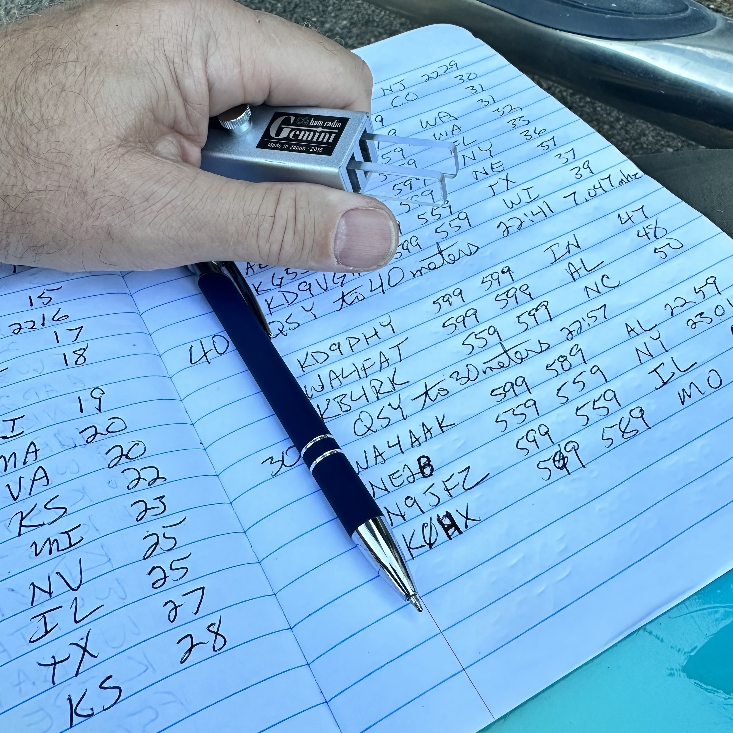
Back to what I was saying, I got to K-2169 and setup in the truck so I have somewhere to sit this time as I planned to stay a while today and didn’t want to have to stand up the whole time. It took me a few minutes to get it all organized, but once I did, everything fit quite well. I wanted to use my N3ZN key, but to be honest, this arrangement literally made it impossible, so I defaulted to the little travel key I have used so much over the last year. I didn’t have a table top that was convenient to setup the other key on and I even tried to sit the N3ZN key on my clipboard, but it was just too difficult and I kept running into problems trying to use it. Hence you see the Gemini cw paddle in my hand for this activation.
Once I settled on the key and radio, I chose 15 meters to get on the air, the band was wide open and even the propagation report said it would do well… Well, FT8 was rocking pretty strong (I tend to use these guys for my beacon report on a band), so I move down into the CW area and start calling CQ…and I call and I call…and nothing. Seems either no one was on the band or they simply could not hear me. It did appear that the band was fading in and out pretty bad though as the RBN would give me a great report one minute and then it would go 3 minutes without a single update. So after what seemed like an eternity on 15 meters, calling CQ with no answers I caved and went down to 17 meters to see what I can scare up.

The hamstick collection at this point. 15 (Green), 17 (Brown), 20 (Yellow), 30 (Blue) & 40 meters (Red) are all represented here (well, 30 meters was on the truck when I took this photo)

So since I had not edited the memories in the sBitx V2 yet for my use, I planned to use the PICO Keyer I picked up a while back, well it worked somewhat, I think it had trouble keying the radio because the radio is looking for contact closure and not a semiconductor so it would work, but it was introducing errors into the code pretty bad. I finally threw in the towel and just used the key the whole time and ran with it. This turned out to work really well though and I really didn’t mind it after all. Once I got home I built a complete set of memories for the keyer complete with all sorts of messages. You get as many memories as you want, they are in sets of twelve, I tested this by copying the CW1 memory and renaming it then I edited the messages and saved it, rebooted the radio (just as a precaution) and the new set of messages were right there in the drop down menu! They are really simple to edit, but you need a keyboard to do it. I didn’t take one with me on this trip hence I didn’t bother with trying till I got back home. If there is demand for it, I will detail how I added a memory and show how to edit the messages and the message names as well.

So I ended up using almost 4 Amp Hours of energy on this activation. Not bad for over 50 contacts in the log. I am happy with that! When I am going to be at the park for a while, I will get all the antennas out and sort them by band like you see below. Well, they are not sorted at this point, but imagine that they are for the story. Then I can change bands quickly and easily as I will lay them near the mount for the truck. The 2” PVC pipe is maxed out too. I don’t think I can get another antenna in it at this point. If you plan to run hamsticks, I recommend that you get some sort of tube to store them in to protect them. They are not very durable in construction so it would be best to try to store them in a way that will make them last.

You see, I know the radio is transmitting as I have been using it at home for the past week or so before taking it to the field. So I get down to 17 meters, find a clear frequency and start calling CQ here. Well things pick up for me here as I get a few answers so I know the radio is in fact working as it should and I didnt do something to it while I had it taken apart… More on that later when I talk about the mods I did to this radio right out of the box.
So after messing around on 17 for a few minutes I hit a dead spot, so I figure it is a good time to QSY down to 20 meters and see what I can find down there. Well, I found all the ham radio ops in the United States and some from across the Atlantic too! I proceed to make over FOURTY contacts in an almost continuous stream in about as many minutes! I was busy! The radio was working great too. At this point, I clear all the callers and decide to try the lower bands for a minute and see what I can do there.

So I hop on 40 meters first as this antenna has consistently been on the upper edge of SWR for my operating preferences, and the sBitx agreed with it showing about 2.1:1 while I was there. Also of note is that the radio self adjusts the output power based on band and SWR from what I can tell. I was running about 20 or so watts on 20 meters and wihtout changing the power setting at all, jumping on 40 meters netted me 9 watts output into the 2.1:1 SWR where on 20 meters I think the SWR was closer to 1.2:1… So I turned up the drive some in an attempt to get the power out consistent across the whole activation. I didnt get it past 15 watts if I remember right… But it was enough to make a few contacts and get some in the log from more local hams as the 20 meter band hops right over the closer states.
Then I finally moved up to 30 meters to see what it could do as well since that was the only antenna I had not tried yet. Well, 30 meters also did not let me down…like 15 meters did… haha. I got it on the band with good SWR and output power and easily made several QSOs on that band to finish up the HF portion of this activation.
The next part is just for fun, but I also recently got a new HT (Handy Talky) radio and was playing with it while out on this day. So I called into the KG4WBI/R 1.25m repeater to see if Roger was monitoring and he was. So then I asked him to switch his radio to VFO and simplex so we could make a 1.25m FM UHF contact. 5 watts was more than enough to make the trip the roughly 3 or so miles it was to his house from my location! So I netted 54 contacts on this day on 5 bands and two modes. I had a great activation and the sBitx pulled quite a long shift on it’s first outing.
Now to discuss some issues I found with the new radio that I am going to look into solving or upgrading. The first one is actually really easy, it needs a fan… or two. The heat sink got SO hot in the two hours I was in the field operating at about 20 to 25 watts. REALLY hot, the whole radio was hot actually and I think this is what made it start doing the next issue..

This is something I noticed after a while, when the radio is getting really warm, it starts to “stutter” in the refresh rate of the screen. I am thinking this is due to thermal throttling of the Raspberry Pi processor in an attempt to prevent sudden death from overheating. I confirmed this was not due to ram overflow by swapping the Pi out with a second one I own that has 8GB of onboard ram and it did it too with minimal use “on the air” back in the shack at home. So my solution is two fold, one is to install a fan on the main heatsink for the power amplifier in the RF deck and a second fan pulling air through the radio chassis where the Pi is located in an attempt to cool the processor as well. I know this will increase current draw from the battery, but I am not concerned with this as my activations normally don’t run over two hours at a time and this limits amp hour usage to usually no more than 3 or 4 amp hours, which even my smaller battery can handle at this time. If adding the fans runs the draw up to 5 amp hours or even 10 in an activation, then I will just take a bigger battery since this is not a backpacking radio in my book. Also, it did work at 25 watts down to 15 watts, depending on band and SWR, for the whole activation. If I were to just turn the power down to 5 watts, it probably wouldn’t get warm enough to matter on the power amplifier considering the size of the heat sink on it. This means I will probably install a small toggle switch to manually cut the power to the fans should I want to run it at true QRP levels in the field. I also plan to wire the fans through a circuit that will automatically turn them on and off as needed to prevent them from just drinking the battery dry when they are not needed. This involves a small temperature sensitive resistor called a thermistor in a voltage divider and a transistor to flow current to the fan. This way if the radio doesn’t get very hot, it wont come on at all. I think I did the math on this device and it will bias the transistor base at about 105F degrees, which is about right for it to protect the electronics. The processor cooling fan could be done the same way (and probably will) but I don’t want this fan to be very large so I am searching for a small 12 VDC fan for this application and also I want to see if I have room to install the processor heatsink, which is not currently installed. This alone will help tremendously, but with long activations the heat will eventually soak the heatsink and we will be right back to square one. This is why I want to add forced air flow to the system…
Even with all the heat buildup, the radio trucked right along and I put over 50 contacts in the log on the first outing! I even got some from overseas in the log!!! It is always good to get some DX in the logbook. I really liked this radio for a station that will be near the truck. The reason for this is that it is fairly large and heavy compared to my other radios, well maybe the Argonaut 5 is similar in weight. This is one of the reasons the Argonaut 5 doesn’t go on activations that stray far from the vehicle too. That guy is heavy, and it is a fairly fragile radio like the sBitx V2. So who knows what I will end up using it for, but for now, it will be one of my POTA radios.


All that aside, the radio works really well for the most part and over time this will be a wonderful little rig to run on activaitons. I plan to get it going on digital modes as well so I can work contacts on FT8, PSK31 and RTTY as well since it does all those modes natively and without the need for an external computer. This was one of the main reasons for getting this radio, I really didn’t want to have to bring an additional computer to the field to do digital modes… Anyway, with all that said, I packed up and on the way out found a few deer wandering around the area and I was able to get a photo of one of them. That was just icing on the cake for a day with so much activity and fun and getting to use my new radio. So until next week, get your radio out and go make a contact with it!

So I have had this nagging thought about toroids.
I have wondered if the hype about certain “mixes” of core materials made THAT much of a difference in things like common mode chokes and such.
FT240-43 Ferrite Core
Well, it turns out, yes…it matters alot. Like more than you could imagine kinds of alot. Let me share my experiment numbers with you.

T130-2 Powdered Iron Core
So to do this test, I used my nanoVNA and the S21 input set to LOGMAG so I can measure the difference between port 0 and port 1 in dB. I also swept the entire HF band space to get points from 1.8 mhz up to 29.7 mhz.


Note this test isn’t to determine which setup is the better setup, (well maybe it is if I am being completely honest) but rather to see if there was enough of a difference to warrant getting the specific composition toroid. If you will notice, the ferrite choke is much larger, this is because I learned from my mistake with the powdered iron version I used in the beginning. I struggled to get 14 turns of RG174 through the powdered iron core so when I ordered the ferrite core, I made sure it was big enough. Lol. My QRP setup for POTA is not ultralight weight, super minimalist portable but rather a “drive the pickup truck to the park and setup near the truck” kind of portable. I also learned when the ferrite core arrived that it would hold quite a few more turns of coax. Well… following my “more is better” philosophy I figured out what length would basically fill the toroid and that turned out to be 6 feet of coax. Hence the ferrite core has 30 turns of RG 316 coax on it.


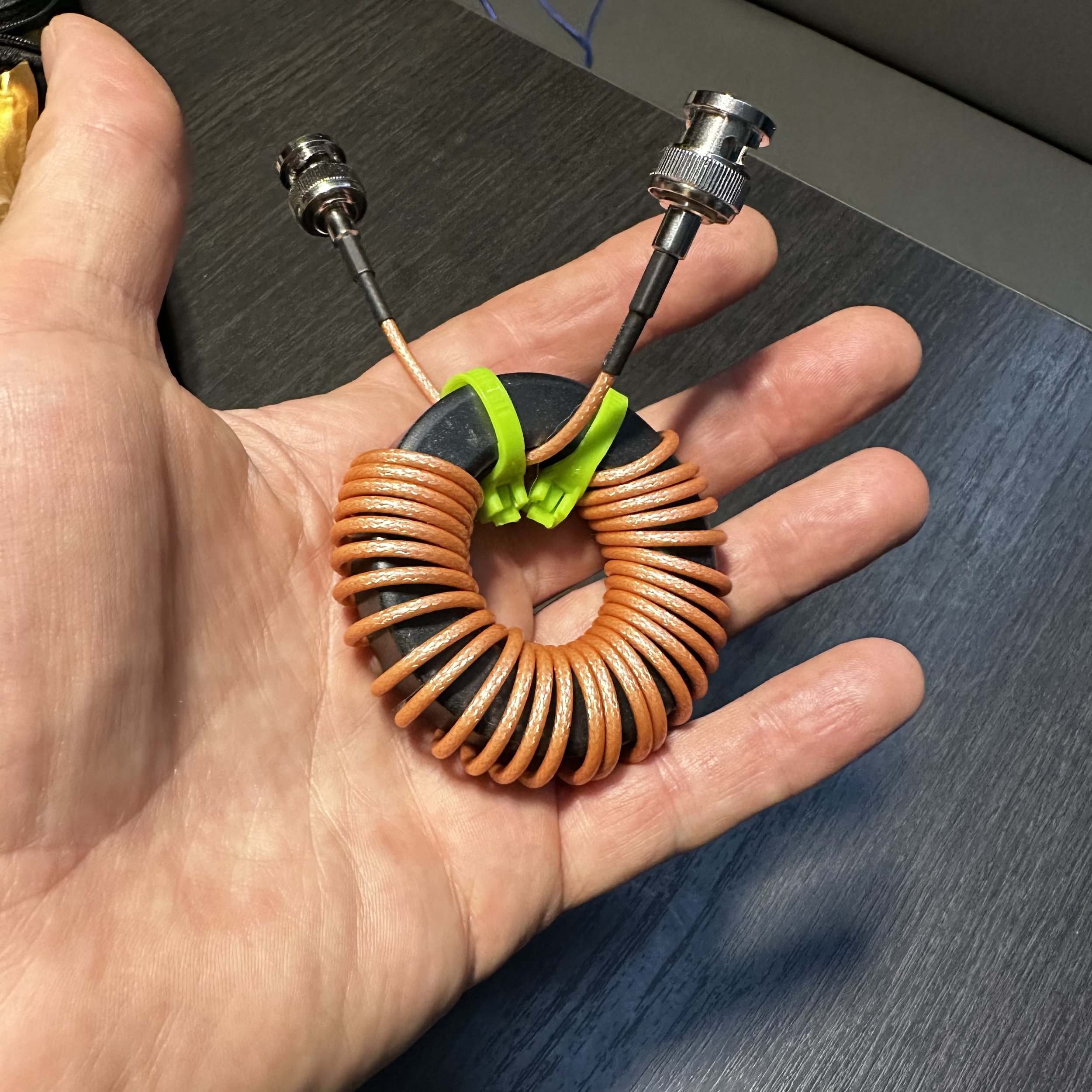
The next thing I needed was a way to actually test the common mode current suppression. You see common mode current flows on the outside of the coax shield only.
This in turn required me to make up a cable that would allow me to connect the coax shield of the choke to both the port 0 and the port 1 inputs on their center pins while coupling the input shields together from those ports.
Enter Youtube at this point on how to use the VNA to perform this test. Of course, the test isnt 100% accurate as I couldnt perform the calibration correctly with the built up cable installed, but it does give me a close approximation to the performance I can expect.
As you can see from the picture above I simple cut a short jumper in half, soldered the shields back together and then soldered the center conductors to the shields attachments of two BNC connectors so I can pass the test signal over the shield only of the cable under test. This works surprisingly well but it is fragile so at some point I plan to put this in a simple project box.

The first one to test was the powdered iron core, which is the one currently in use in my POTA kit. I had bought this core with not much though being put into it. An RF choke is an RF choke is an RF choke was the thought process here. So I added it to my coax and happily used it for a while but occasionally got unwanted dits and dahs on my code if the coax was near the key cable. I noticed I could simply reposition the coax and it would stop causing interference. This made me question the choke’s effectiveness and here we are now. The VNA is set to 10dB per division and the whole amateur band with 1.8 mhz on the left and 30 mhz on the right. To save you from squinting I made a chart at or close to the bands I use to see the relative suppression and it is below for this choke.

As you can see from the chart, it works really well on 17, 15 & 12 meters but not really well past those. I dont know why it produces a 54dB null on 15 meters but that is kinda awesome. The performance on 1.8 mhz though is abysmal and I am guessing this is why I was getting RF induced into the keying line on 40 meters with only 13dB of suppression. So then I put the new ferrite choke into circuit and the waveform and chart are below.


Holy moly what a difference! The first thing I noticed was how broadbanded it was and the next thing was how low the waveform was! The poorest performers were the high and low portions of 10 meters and they still almost made 30dB!!! Wow! That 80 meter null is phenomenal and has me wanting to try a hamstick on that band. So this simply proves conclusively that I am an idiot and should have listened to start with…
Following my idea of “more is better” I decided to couple both chokes in series to see if the deep null on 15 meters from the powdered iron core and the 80 meter null from the ferrite would simply “add” together for some sort of magical double dip monster choke.


Well…It didn’t go quite to plan. There are two distinct dips… Instead of adding the two plots, it seems to more have averaged them together. This result is kinda disappointing to be honest. I was hoping to get over 50dB on two bands, but so is life. I am sure there is solid math somewhere that explains this in detail, but I honestly don’t know it, this is why I like to experiment and tinker with things. I can still learn something even if I dont have all the background (like the math knowledge) for a given idea. Also a quick note, my note at the bottom is wrong as it improved 17 meters as well. But it was late and I was getting tired. Lol.
In conclusion, if you plan to make a common mode choke for your HF coax, use the 43 mix ferrite for good performance across the band. Also, I didn’t try varying the number of wraps either. This will change the performance characteristics of the choke as well, so at some point I will probably do that but for now, I will just get on the air with my new choke and be happy.
I hope this helps someone on their common mode choke journey and keeps them from having to learn the same things I did the hard way so until next time, get on the air!!!