WK4DS Amateur Radio Blog
Search Posts
So I have had this nagging thought about toroids.
I have wondered if the hype about certain “mixes” of core materials made THAT much of a difference in things like common mode chokes and such.
FT240-43 Ferrite Core
Well, it turns out, yes…it matters alot. Like more than you could imagine kinds of alot. Let me share my experiment numbers with you.

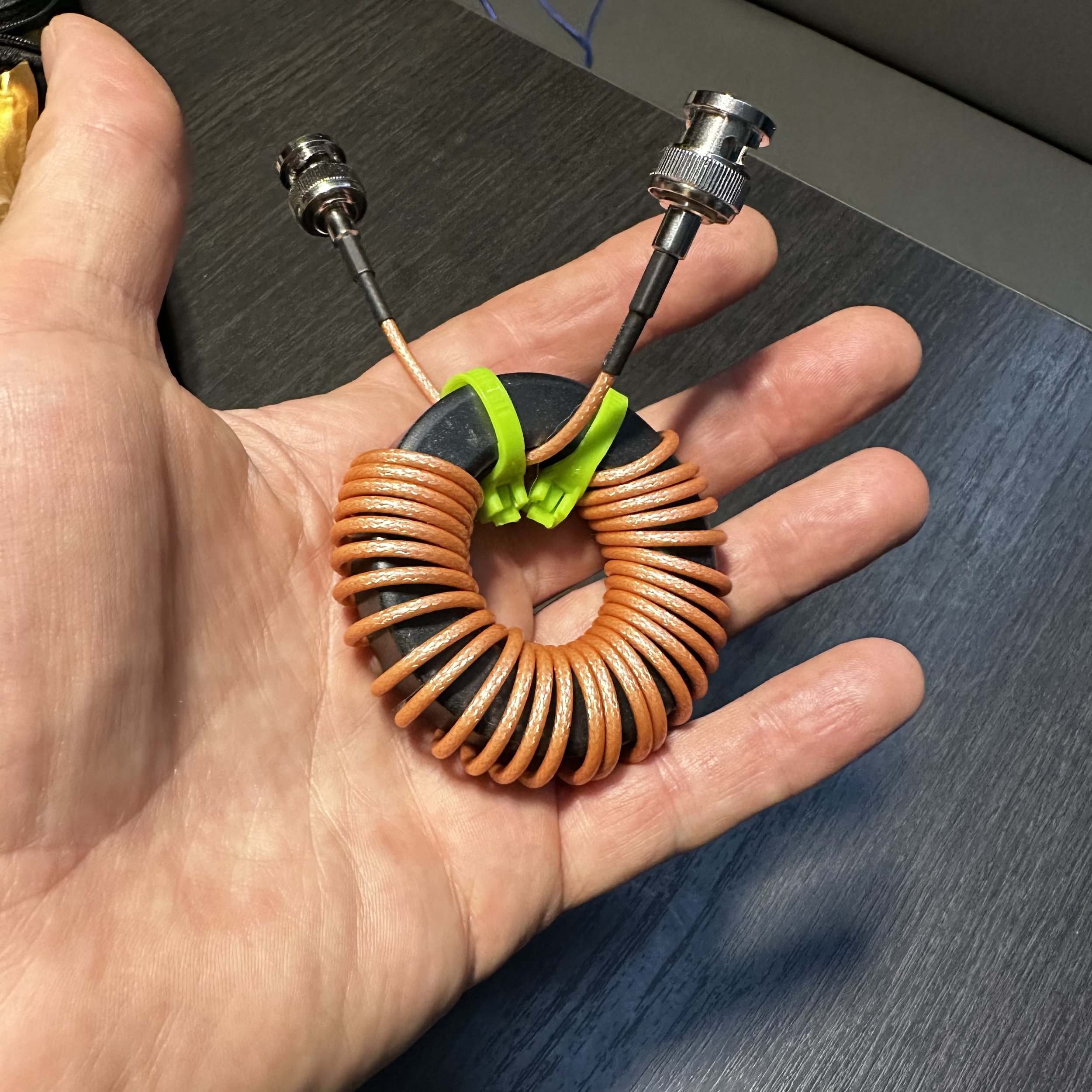
T130-2 Powdered Iron Core
So to do this test, I used my nanoVNA and the S21 input set to LOGMAG so I can measure the difference between port 0 and port 1 in dB. I also swept the entire HF band space to get points from 1.8 mhz up to 29.7 mhz.


Note this test isn’t to determine which setup is the better setup, (well maybe it is if I am being completely honest) but rather to see if there was enough of a difference to warrant getting the specific composition toroid. If you will notice, the ferrite choke is much larger, this is because I learned from my mistake with the powdered iron version I used in the beginning. I struggled to get 14 turns of RG174 through the powdered iron core so when I ordered the ferrite core, I made sure it was big enough. Lol. My QRP setup for POTA is not ultralight weight, super minimalist portable but rather a “drive the pickup truck to the park and setup near the truck” kind of portable. I also learned when the ferrite core arrived that it would hold quite a few more turns of coax. Well… following my “more is better” philosophy I figured out what length would basically fill the toroid and that turned out to be 6 feet of coax. Hence the ferrite core has 30 turns of RG 316 coax on it.


The next thing I needed was a way to actually test the common mode current suppression. You see common mode current flows on the outside of the coax shield only.
This in turn required me to make up a cable that would allow me to connect the coax shield of the choke to both the port 0 and the port 1 inputs on their center pins while coupling the input shields together from those ports.
Enter Youtube at this point on how to use the VNA to perform this test. Of course, the test isnt 100% accurate as I couldnt perform the calibration correctly with the built up cable installed, but it does give me a close approximation to the performance I can expect.
As you can see from the picture above I simple cut a short jumper in half, soldered the shields back together and then soldered the center conductors to the shields attachments of two BNC connectors so I can pass the test signal over the shield only of the cable under test. This works surprisingly well but it is fragile so at some point I plan to put this in a simple project box.

The first one to test was the powdered iron core, which is the one currently in use in my POTA kit. I had bought this core with not much though being put into it. An RF choke is an RF choke is an RF choke was the thought process here. So I added it to my coax and happily used it for a while but occasionally got unwanted dits and dahs on my code if the coax was near the key cable. I noticed I could simply reposition the coax and it would stop causing interference. This made me question the choke’s effectiveness and here we are now. The VNA is set to 10dB per division and the whole amateur band with 1.8 mhz on the left and 30 mhz on the right. To save you from squinting I made a chart at or close to the bands I use to see the relative suppression and it is below for this choke.

As you can see from the chart, it works really well on 17, 15 & 12 meters but not really well past those. I dont know why it produces a 54dB null on 15 meters but that is kinda awesome. The performance on 1.8 mhz though is abysmal and I am guessing this is why I was getting RF induced into the keying line on 40 meters with only 13dB of suppression. So then I put the new ferrite choke into circuit and the waveform and chart are below.


Holy moly what a difference! The first thing I noticed was how broadbanded it was and the next thing was how low the waveform was! The poorest performers were the high and low portions of 10 meters and they still almost made 30dB!!! Wow! That 80 meter null is phenomenal and has me wanting to try a hamstick on that band. So this simply proves conclusively that I am an idiot and should have listened to start with…
Following my idea of “more is better” I decided to couple both chokes in series to see if the deep null on 15 meters from the powdered iron core and the 80 meter null from the ferrite would simply “add” together for some sort of magical double dip monster choke.


Well…It didn’t go quite to plan. There are two distinct dips… Instead of adding the two plots, it seems to more have averaged them together. This result is kinda disappointing to be honest. I was hoping to get over 50dB on two bands, but so is life. I am sure there is solid math somewhere that explains this in detail, but I honestly don’t know it, this is why I like to experiment and tinker with things. I can still learn something even if I dont have all the background (like the math knowledge) for a given idea. Also a quick note, my note at the bottom is wrong as it improved 17 meters as well. But it was late and I was getting tired. Lol.
In conclusion, if you plan to make a common mode choke for your HF coax, use the 43 mix ferrite for good performance across the band. Also, I didn’t try varying the number of wraps either. This will change the performance characteristics of the choke as well, so at some point I will probably do that but for now, I will just get on the air with my new choke and be happy.
I hope this helps someone on their common mode choke journey and keeps them from having to learn the same things I did the hard way so until next time, get on the air!!!