60m Band Module Part 5: SSB Operation
If this is your first time seeing this project, please go back and take a look at the full series so you will be up to speed on this project.
- Part 1: Initial Conversion and Filter Design
- Part 2: Crystal Selection and Mixer Circuits
- Part 3: Field Testing and Troubleshooting
The Single Side Band Problem
Today, we are taking a look at the TenTec Scout 555 60m band module that we built and figure out how to make it work on single side band properly. This band module was created by using a donor 80 m band module and from there things were changed and re-tuned to make it work on the 60 m amateur radio band.
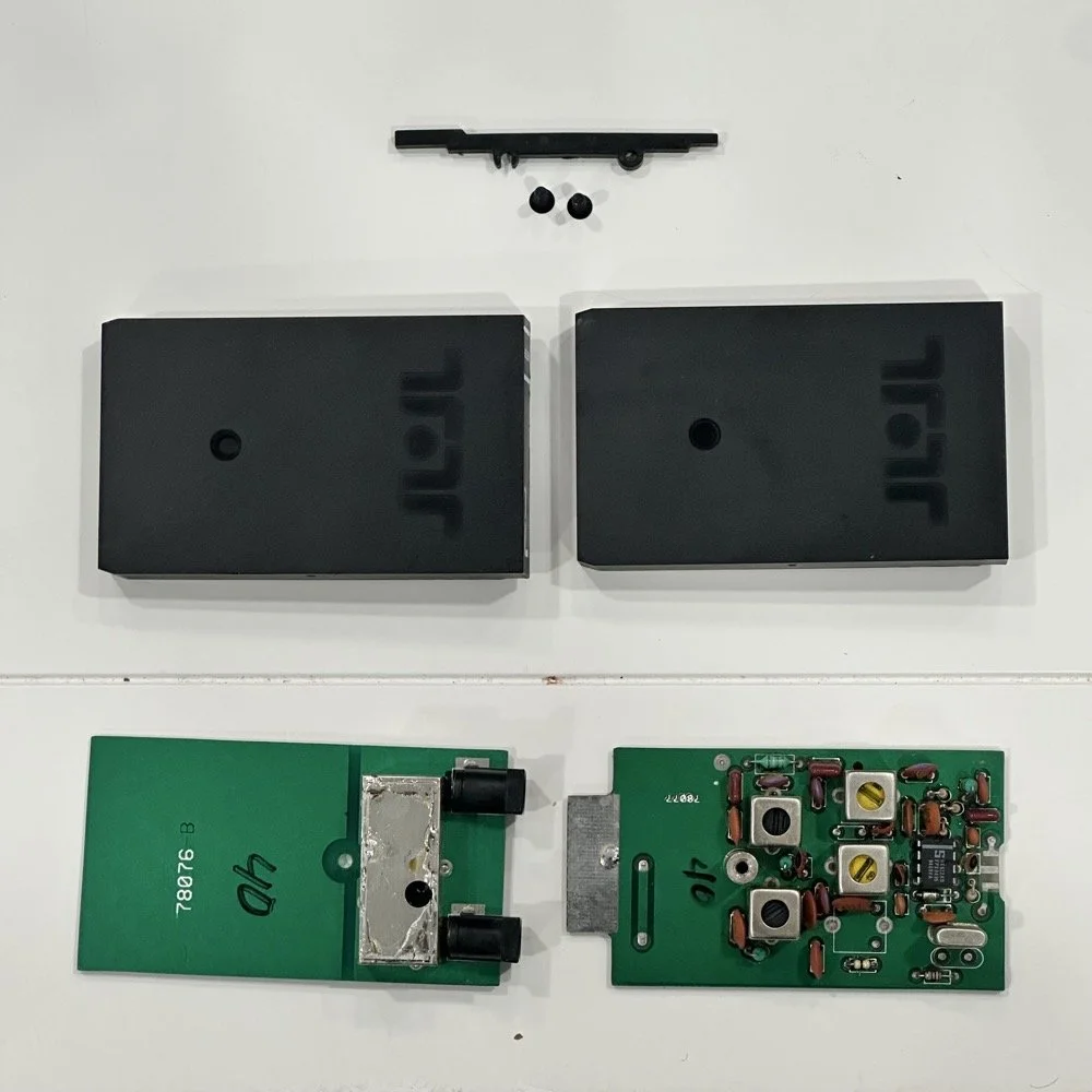
One thing that has turned up though is that the 80 m band module operates on lower side band. To get the side band correctly oriented for the 60 m band I need it to transmit on the upper side band. This is not the normal convention for amateur radio operation though. The normal convention is as follows; bands 30 meters and lower, such as 40, 80, 160 and so on, will use lower side band. All bands 20 meters and above use upper side band instead. Someone a long time ago decided this was how we will do things going forward and here we are. Well for some reason, the 60 meter band is not like the other lower bands. It is using upper side band so I have to figure this out. The next step I have to do is figure out how the radio determines what band module is installed, and which side band it chooses. The radio automatically chooses either upper or lower side band, depending on the band module in use. So something is either telling the radio to monitor the actual frequency or it is looking at the band modules themselves and it is determining it that way somehow. All we have to do is figure out how it’s determining it and tell it to choose something different. Simple enough.
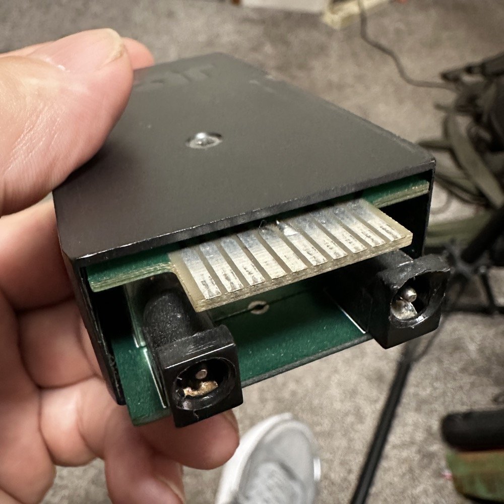
40 meter band module showing the soldered in ground jumper installed on pin 6.
Finding what triggers the shift from upper to lower side band
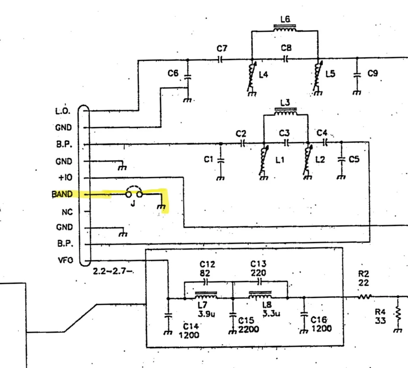
Everything we need to figure this out is in the TenTec Scout 555 owners manual. The manual has an complete set of schematic diagrams on the radio inside. I first start by looking at the band module schematic itself and found that there is a pin marked “band” with a jumper shown on it. This is a very suspicious connection and has me very interested in this particular pin. So this is where I’m going to start my journey since this sounds like it is what tells the radio which band the it is operating on. The next thing I had to do was figure out where it went in the radio, so I dig out the prints and found what follows…
The first image is an exert from the schematic of the band module itself showing pin 6 “band” being grounded with an optional jumper.
Band Module Edge Connector Pinout showing Pin 6 as the “Band” pin.
The next stop for this circuit is the Low Level driver board and it lands on a pin on connector 48.
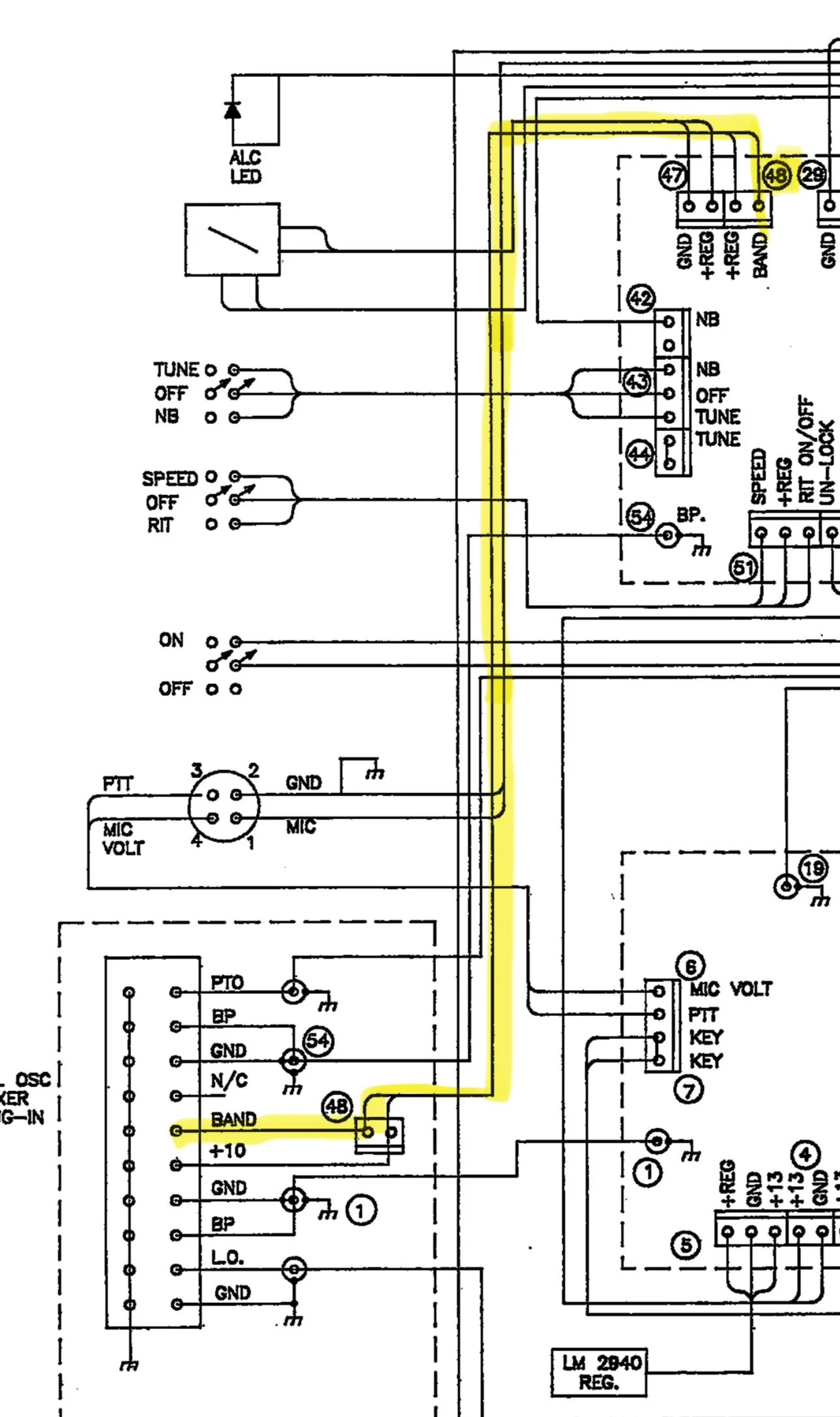
Section of the Low Level Driver Board Schematic showing the path from the “band” pin on the module edge connector up to a pin on cable 48.
It then travels along cable 48 over to the Low Level Driver board.
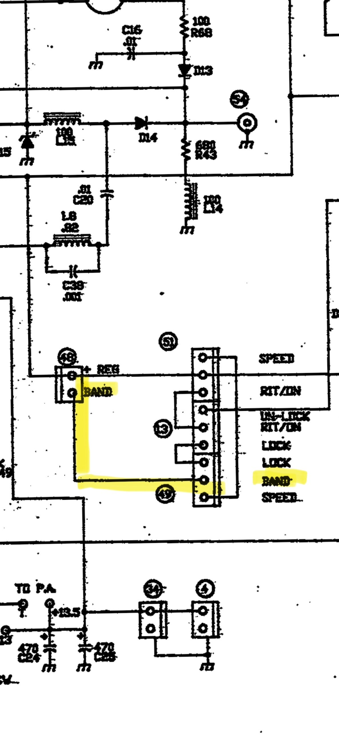
Low Level Driver board wiring showing connector 48 and 49 for the “band” selector.
The next place it went was from connector 48 to connector 49 on the low level driver board where it exited the low level driver board. I am going to be honest here, this wiring makes no sense other than to add two points of corrosion with bayonet connectors that are not needed. There was no reason to goto the LLD board just to exit the board without doing any work with this signal from the band module. Yet, so is life…
It leaves connector 49 on the low-level driver board and goes to the Logic board. Once on the logic board, it goes to pin 10 on the PIC16C57 controller Chip. This chip is probably being used to control all sorts of stuff, but this pin is being pulled low when the band module is grounded and it is being pulled high through R14 (4.7K ohm) resistor when the band module is not jumped to ground.
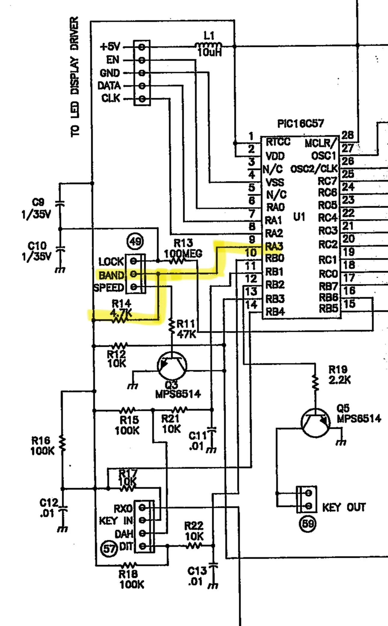
After tracking it down to the PIC controller, I have come to the conclusion that if you pull this line low (tied to ground), it determines one side band mode and if it is left ungrounded, it is pulled high by a pull up resistor to set another side band mode. So I went and retrieved my multi-meter and checked a full set of band modules to see and this is what I found:
10m - open
12m - open
15m - open
20m - open
30m - shorted
40m - shorted
80m - shorted
160m - shorted
60m Single Side Band on a TenTec Scout 555 is hard!
Once I saw this pattern I knew that this was how it knew what each mode needed to be. It had no way of knowing which band, but it knew which side band mode…or so I thought… As fate would have it, I learned something else today. I took my 60m band module to the workbench and de-soldered this ground contact so it would transmit on upper side band. Knowing that I didn’t touch any of the other stuff in the module I merrily trotted back to the shack to test it out.
Turns out more happens with the radio than just choosing the side band… Turns out there is a second thing that happens when you cut this trace. You see when you look at the chart of the frequency path on the NA5M website, you see that 30 meters and below, the 6.142mhz IF is subtracted from the Local Oscillator sum and 20 meters and above it is added. So when I cut the trace, the radio now transmitted on 17.616mhz and not 5.332mhz! Yeah, sure, now I had upper side band but now I was on the other end of the world from where I needed to be… Little good having upper side band does me if I am off frequency by over 10mhz!!!
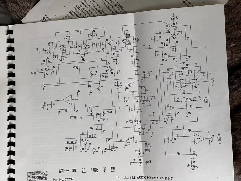
I figured out the following:
The band module has a pin on the edge connector that when grounded, makes the radio operate on lower side band and it subtracts the 6.142mhz IF from the signal. When it is open, the exact opposite happens. So what I need is for the radio to be like a “low band” module for the mixer, but use upper side band for the voice and some of the data modes. This is the problem I need to solve and the answer was on YouTube. After looking at the problem for a while and understanding how the two sidebands are literal mirror images of each other spaced out from the center frequency. I finally found a fellow ham from Australia that had the answer. Simply flip the audio frequencies only and adjust the radio as if it were lower side band. This sounds silly till you see his video. I currently have center tapped audio transformers on the way so I can build a circuit that mixes a 2500hz tone with the audio stream as the audio passes through a diode ring mixer. This will invert the frequencies when it does this. If his video is not fake, I will have solved the SSB problem on the Scout 60 module. Sure it will take an homebrew external converter module, but at least it will work! I have to invert the audio on both transmit and receive so I have to control the microphone input as well as the speaker output. The speaker is easy as I can simple grab the headphone jack audio and process it to a set of headphones or external speaker, but I will have to put microphone connectors on the unit as well so I can intercept the audio from the microphone as well as have it trip a relay when you press the “push to talk” button. All of this should be pretty easy to accomplish so I am confident this will work.
So here is the plan, I want to use that pin right beside the “band” pin on the module edge connector to ground it. Then I can route that to a new plug on the back of the radio to allow me to control a relay with it. This will “enable” the reversing circuit to get the audio corrected for use with this module. Since all the other band modules don’t use this pin, it will only work with the 60 meter module. This is if I have to build the circuit outside of the radio too. If I can get it to fit inside the radio, then I can make the whole thing look original and not need a small adapter to correct the sound and microphone audio. Other wise, I will be piping it through a converter box with the ring mixer in it and a relay to switch the path from transmit to receiver.
The TenTec Scout 555 owners manual has a lot of the information that I need to make this happen, but it doesn’t tell you everything. It mostly describes circuits so you understand what your adjusting it, to trim it back in and get it running right.This means you have to figure out what is going on with the circuits so you can understand how to modify them. This is the hard part for me. For now, at least, the SSB problem remains. I hope to be able to solve it, but right now it looks a little unlikely…unless you know something that I dont and see it in the photo of the schematic above.. haha. If you see a possible solve, please email me or leave a comment and lets talk about it, I am really enjoying this project and would love to get that one last mode to work right.
You can help support this channel by using these Amazon Affiliate Links as well:
QRP/Portable Radios:
Antennas & Tuning:
CW Equipment:
Power & Accessories:
Organization & Transport:
BONUS ITEMS (Optional 16-20):
73
WK4DS - David