WK4DS Amateur Radio Blog
Search Posts
60m Band Module Part 5: SSB Operation
Getting SSB to work on a converted band module for 60 meters is tougher than I thought. It takes mods in the radio too…or it is not possible at all. One or the other is the fate of this TenTec Scout 555 HF radio and the 60 meter band module project.
If this is your first time seeing this project, please go back and take a look at the full series so you will be up to speed on this project.
- Part 1: Initial Conversion and Filter Design
- Part 2: Crystal Selection and Mixer Circuits
- Part 3: Field Testing and Troubleshooting
The Single Side Band Problem
Today, we are taking a look at the TenTec Scout 555 60m band module that we built and figure out how to make it work on single side band properly. This band module was created by using a donor 80 m band module and from there things were changed and re-tuned to make it work on the 60 m amateur radio band.
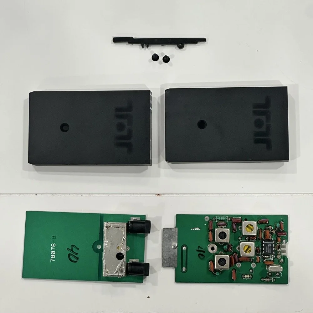
One thing that has turned up though is that the 80 m band module operates on lower side band. To get the side band correctly oriented for the 60 m band I need it to transmit on the upper side band. This is not the normal convention for amateur radio operation though. The normal convention is as follows; bands 30 meters and lower, such as 40, 80, 160 and so on, will use lower side band. All bands 20 meters and above use upper side band instead. Someone a long time ago decided this was how we will do things going forward and here we are. Well for some reason, the 60 meter band is not like the other lower bands. It is using upper side band so I have to figure this out. The next step I have to do is figure out how the radio determines what band module is installed, and which side band it chooses. The radio automatically chooses either upper or lower side band, depending on the band module in use. So something is either telling the radio to monitor the actual frequency or it is looking at the band modules themselves and it is determining it that way somehow. All we have to do is figure out how it’s determining it and tell it to choose something different. Simple enough.
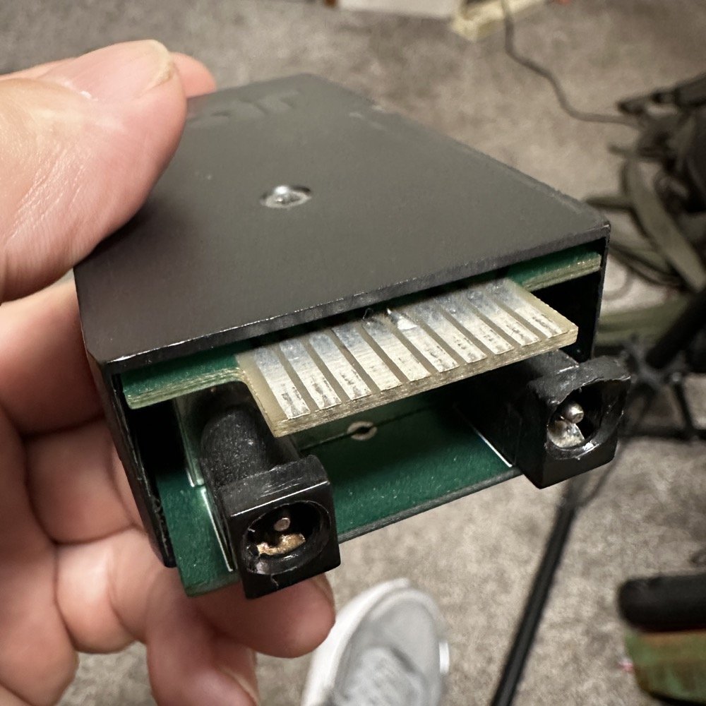
40 meter band module showing the soldered in ground jumper installed on pin 6.
Finding what triggers the shift from upper to lower side band
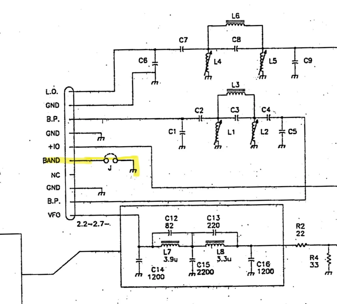
Everything we need to figure this out is in the TenTec Scout 555 owners manual. The manual has an complete set of schematic diagrams on the radio inside. I first start by looking at the band module schematic itself and found that there is a pin marked “band” with a jumper shown on it. This is a very suspicious connection and has me very interested in this particular pin. So this is where I’m going to start my journey since this sounds like it is what tells the radio which band the it is operating on. The next thing I had to do was figure out where it went in the radio, so I dig out the prints and found what follows…
The first image is an exert from the schematic of the band module itself showing pin 6 “band” being grounded with an optional jumper.
Band Module Edge Connector Pinout showing Pin 6 as the “Band” pin.
The next stop for this circuit is the Low Level driver board and it lands on a pin on connector 48.
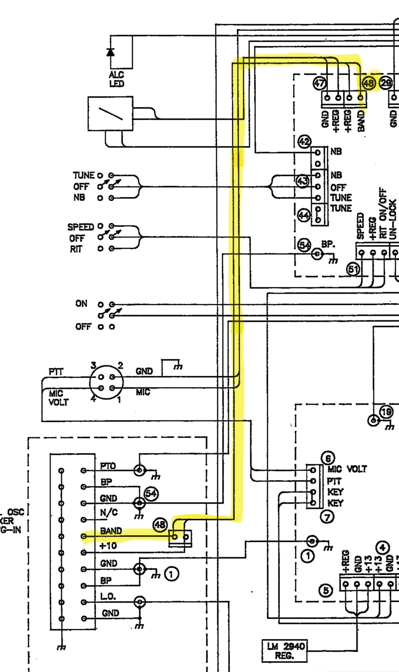
Section of the Low Level Driver Board Schematic showing the path from the “band” pin on the module edge connector up to a pin on cable 48.
It then travels along cable 48 over to the Low Level Driver board.
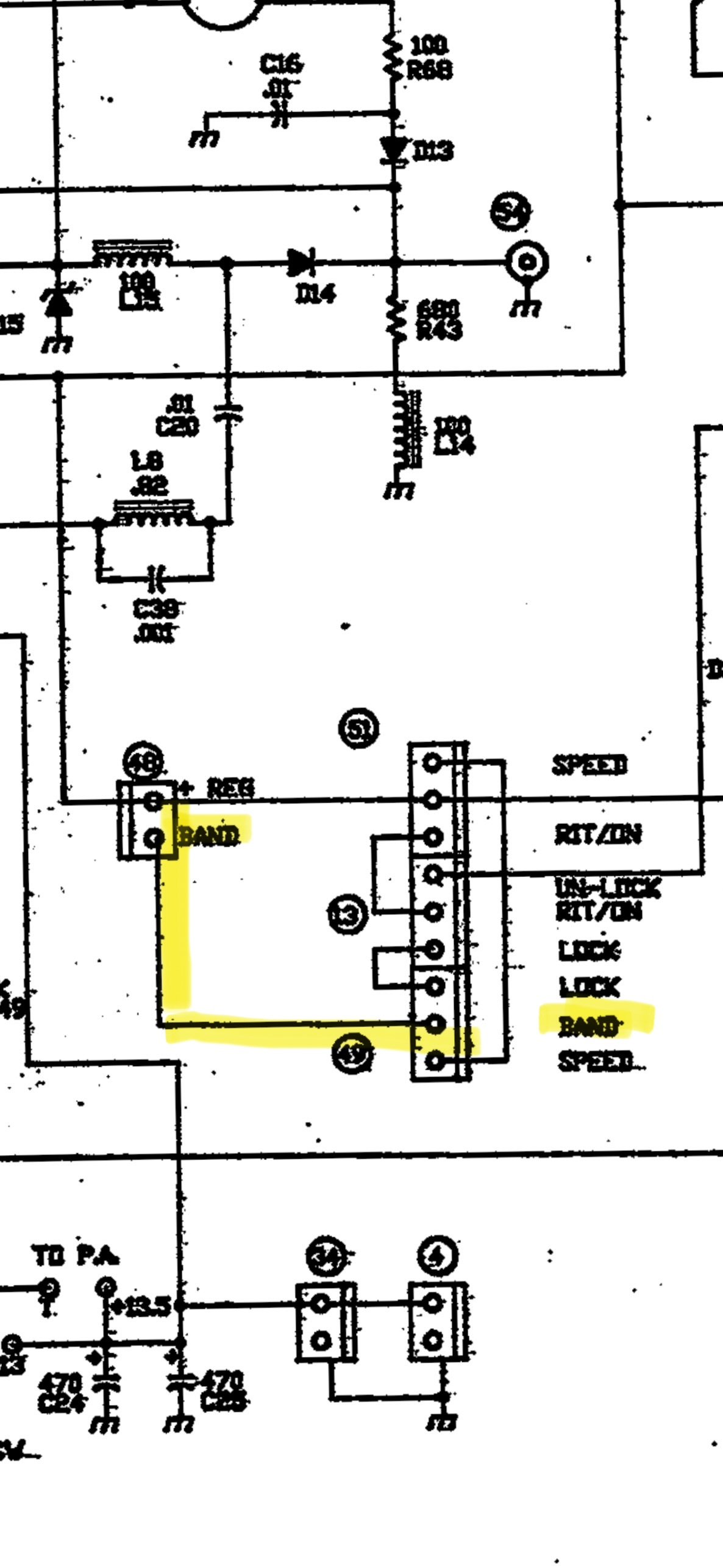
Low Level Driver board wiring showing connector 48 and 49 for the “band” selector.
The next place it went was from connector 48 to connector 49 on the low level driver board where it exited the low level driver board. I am going to be honest here, this wiring makes no sense other than to add two points of corrosion with bayonet connectors that are not needed. There was no reason to goto the LLD board just to exit the board without doing any work with this signal from the band module. Yet, so is life…
It leaves connector 49 on the low-level driver board and goes to the Logic board. Once on the logic board, it goes to pin 10 on the PIC16C57 controller Chip. This chip is probably being used to control all sorts of stuff, but this pin is being pulled low when the band module is grounded and it is being pulled high through R14 (4.7K ohm) resistor when the band module is not jumped to ground.
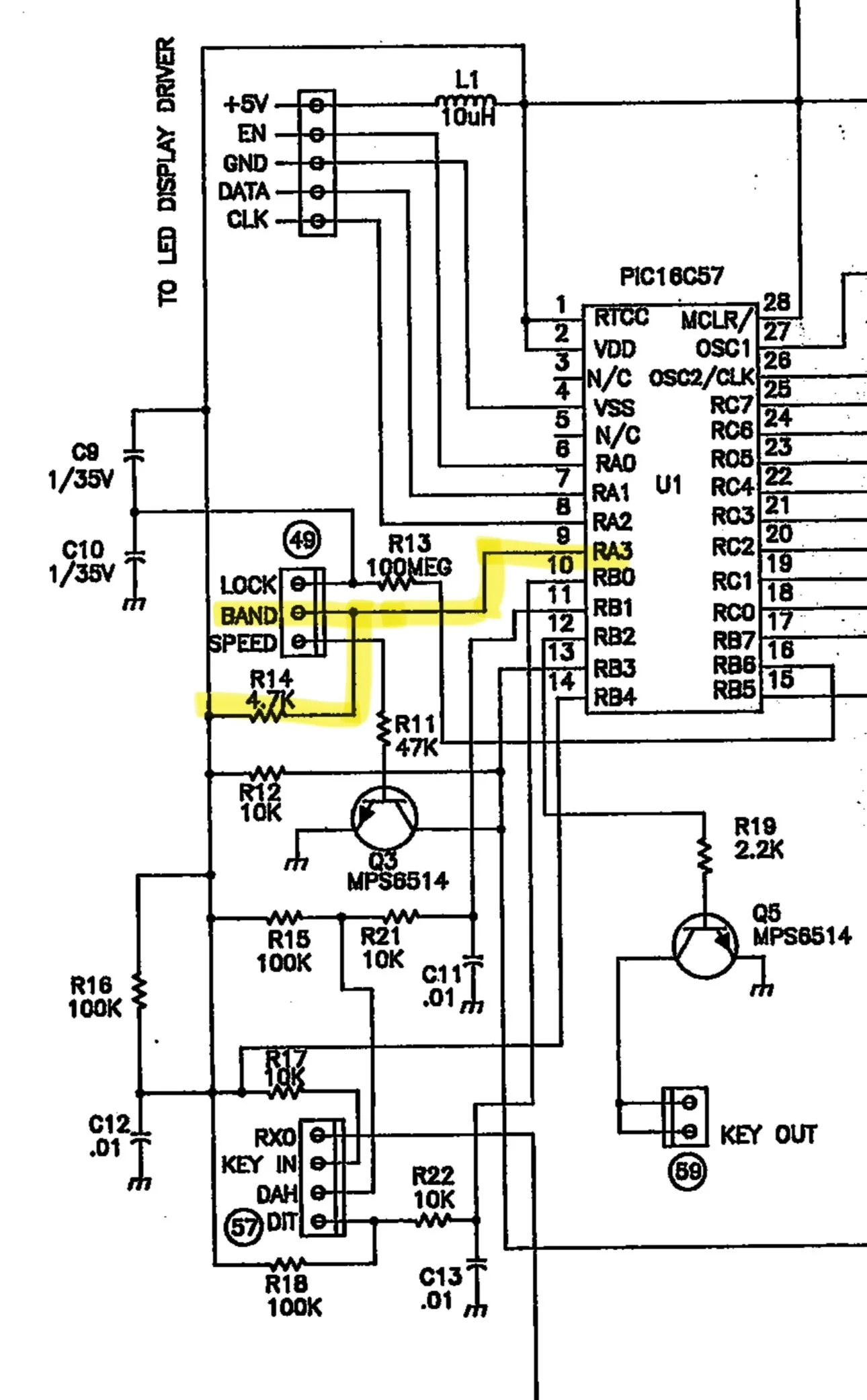
After tracking it down to the PIC controller, I have come to the conclusion that if you pull this line low (tied to ground), it determines one side band mode and if it is left ungrounded, it is pulled high by a pull up resistor to set another side band mode. So I went and retrieved my multi-meter and checked a full set of band modules to see and this is what I found:
10m - open
12m - open
15m - open
20m - open
30m - shorted
40m - shorted
80m - shorted
160m - shorted
60m Single Side Band on a TenTec Scout 555 is hard!
Once I saw this pattern I knew that this was how it knew what each mode needed to be. It had no way of knowing which band, but it knew which side band mode…or so I thought… As fate would have it, I learned something else today. I took my 60m band module to the workbench and de-soldered this ground contact so it would transmit on upper side band. Knowing that I didn’t touch any of the other stuff in the module I merrily trotted back to the shack to test it out.
Turns out more happens with the radio than just choosing the side band… Turns out there is a second thing that happens when you cut this trace. You see when you look at the chart of the frequency path on the NA5M website, you see that 30 meters and below, the 6.142mhz IF is subtracted from the Local Oscillator sum and 20 meters and above it is added. So when I cut the trace, the radio now transmitted on 17.616mhz and not 5.332mhz! Yeah, sure, now I had upper side band but now I was on the other end of the world from where I needed to be… Little good having upper side band does me if I am off frequency by over 10mhz!!!
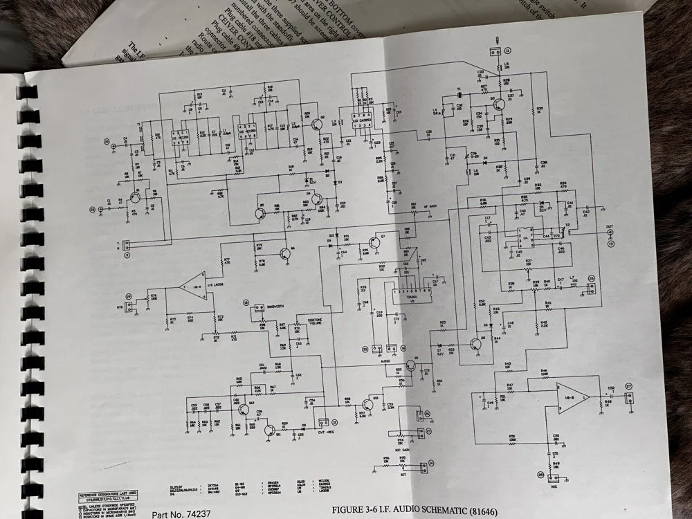
I figured out the following:
The band module has a pin on the edge connector that when grounded, makes the radio operate on lower side band and it subtracts the 6.142mhz IF from the signal. When it is open, the exact opposite happens. So what I need is for the radio to be like a “low band” module for the mixer, but use upper side band for the voice and some of the data modes. This is the problem I need to solve and the answer was on YouTube. After looking at the problem for a while and understanding how the two sidebands are literal mirror images of each other spaced out from the center frequency. I finally found a fellow ham from Australia that had the answer. Simply flip the audio frequencies only and adjust the radio as if it were lower side band. This sounds silly till you see his video. I currently have center tapped audio transformers on the way so I can build a circuit that mixes a 2500hz tone with the audio stream as the audio passes through a diode ring mixer. This will invert the frequencies when it does this. If his video is not fake, I will have solved the SSB problem on the Scout 60 module. Sure it will take an homebrew external converter module, but at least it will work! I have to invert the audio on both transmit and receive so I have to control the microphone input as well as the speaker output. The speaker is easy as I can simple grab the headphone jack audio and process it to a set of headphones or external speaker, but I will have to put microphone connectors on the unit as well so I can intercept the audio from the microphone as well as have it trip a relay when you press the “push to talk” button. All of this should be pretty easy to accomplish so I am confident this will work.
So here is the plan, I want to use that pin right beside the “band” pin on the module edge connector to ground it. Then I can route that to a new plug on the back of the radio to allow me to control a relay with it. This will “enable” the reversing circuit to get the audio corrected for use with this module. Since all the other band modules don’t use this pin, it will only work with the 60 meter module. This is if I have to build the circuit outside of the radio too. If I can get it to fit inside the radio, then I can make the whole thing look original and not need a small adapter to correct the sound and microphone audio. Other wise, I will be piping it through a converter box with the ring mixer in it and a relay to switch the path from transmit to receiver.
The TenTec Scout 555 owners manual has a lot of the information that I need to make this happen, but it doesn’t tell you everything. It mostly describes circuits so you understand what your adjusting it, to trim it back in and get it running right.This means you have to figure out what is going on with the circuits so you can understand how to modify them. This is the hard part for me. For now, at least, the SSB problem remains. I hope to be able to solve it, but right now it looks a little unlikely…unless you know something that I dont and see it in the photo of the schematic above.. haha. If you see a possible solve, please email me or leave a comment and lets talk about it, I am really enjoying this project and would love to get that one last mode to work right.
You can help support this channel by using these Amazon Affiliate Links as well:
QRP/Portable Radios:
Antennas & Tuning:
CW Equipment:
Power & Accessories:
Organization & Transport:
BONUS ITEMS (Optional 16-20):
73
WK4DS - David
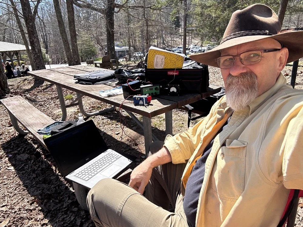
Over 80 POTA QSOs in “less than ideal” conditions…
I activated US-2169 (Cloudland Canyon State Park) and made over 80 CW contacts despite lawnmowers, kids, and Murphy's Law doing its best to sabotage the activation. Here's what happened when "less than ideal" conditions tried to stop me!
Let’s talk about something that not a lot of people consider…what do you do when you get to a park and things are not like you imagined? Do you turn around and leave? Do you complain to park management? Do you setup and “get your ten” as fast as possible? What? Leave it in the comments what you do when you have problems like I did today?
POTA Park Conditions
Here is the setup, today I went to US-2169 (Cloudland Canyon State Park) to get on the air with my little Penntek TR-35 QRP radio and found some interesting things happening at the park today. As you can see below the weather was basically perfect for a POTA activation today. It is still early spring here so the top of the mountain is still not showing much signs, but the valley is getting ready…so to speak. Some trees are turning green and some of the dogwood trees are starting to bloom so we are getting started. The temperature was nice in the mid 60s today and it was sunny so it was really nice. I Did find the direct sun to be annoying to be honest as it kept causing a lot of glare on my computer which made it hard to see at times, but I powered through this first obstacle…
My POTA station for today consisting of the Penntek TR-35, the Begali Traveler CW Key and my Dell Inspiron computer for logging.
The next thing I ran into was the kids, there were so many kids in the park today, it must be some spring break or something as there were a lot of groups of children like you see in the photo above (in the background) and they were…well…being kids… This in itself isn’t a problem, but I failed to bring any sort of flagging tape to mark my coax with so I was constantly looking over my right shoulder to make sure no one was about to walk into it. Actually, I only had to do this for a little while as there was something else that happened a little later that basically ran the kids off for me… haha. The lawnmowers…
The POTA HF Radio System Setup - Reliance Antenna
Anyway, let’s look at the antenna setup today to see what made it work so well. I started with two throw lines today so I could elevate the whole antenna off the ground. You see, I was using the Reliance Antenna Bugout 40m EFHW again today and wanted to replicate what I had back in Florida.
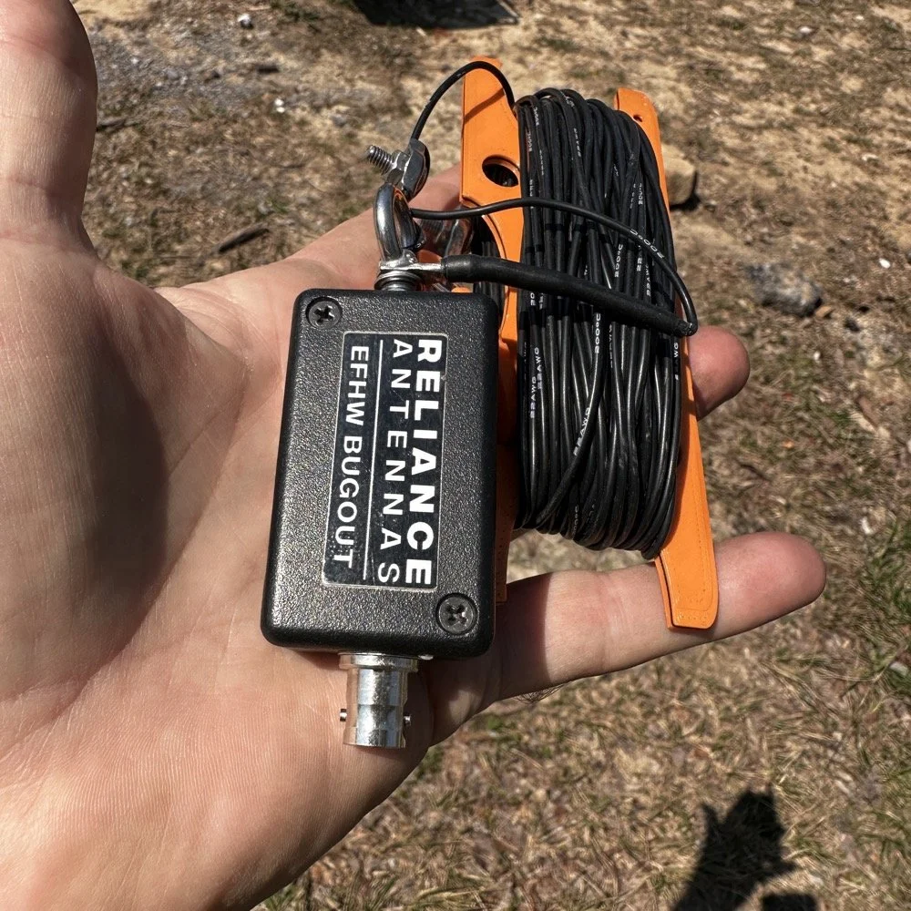
Today saw me use the Reliance Antenna Bugout 40m EFHW antenna to great effect even with all the problems.
I threw a line about 15 feet up over a large limb on the nearby tree to create the first point and this is where the coax went up to the transformer. I didn’t use a tuner today so I stayed on 20 meters the entire time today.
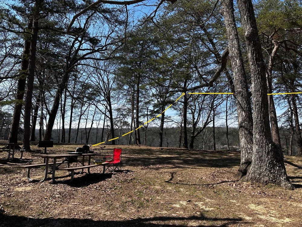
POTA antenna installation showing the 1st elevated point of the antenna transformer from the operating position.
I ended up tying the antenna lift rope (it is actually a small cord but you get the point) to the grill right behind the table to the left in the above photo. I used a Velcro tie to attach the end of the coax to the “possibles” bag on the table as it is heavy and the coax is really light and I figured it would hold it just fine…which it did. Next came the haul line to lift the antenna into the distal tree with the high end about 30 feet up. I use a stainless steel throw weight that I made in the machine shop so I can send this thing into the stratosphere if I want…haha. The wide angle photo below shows where the antenna was in the trees. You can also see another family at the picnic table in the background… more kids… haha. The good thing about using two haul lines in that the entirety of the antenna is WAY above where anyone could even get close to it. I was also using QRP power so there was no danger of RF issues here. The height is also beneficial for propagation and we will see a little later that it did in fact help.
Now, this antenna doesn’t have a counter poise of any kind so it uses the coax shield for the counter poise. To keep the stray RF out of the radio, I use a special coax from ABR Industries that has a ferrite common mode choke in one end. I simply put this end on the radio side and this allows the antenna to access the coax shield for counter poise use and also it keeps the common mode currents out of the radio… At least that is what I hope is happening, the strategy seems to work so I am running with it.
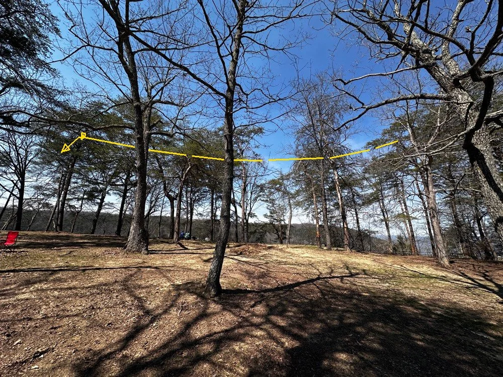
Position of the 40m EFHW antenna today for my POTA activation. Well above the ground!
POTA Activation Highlights
So once the radio was all put together and powered up on the table, I connected the speakers from my custom built project. This is a power pack with a 3aH Bioenno battery in a project box with a power-pole receptacle and a set of speakers so the Penntek TR-35 can be used like a regular radio since it has no internal speaker. I like running it like this if the ambient noise level is low enough as it allows the people around me to hear the CW as well. This sometime sparks interest and people will come over and ask me about what I am doing. A perfect5 opportunity to share with someone about amateur radio.
I started listening around a little and found 14.061mhz was clear after listening for a while. I have found that I will hunt me a clear frequency then get out the logging computer, boot it up and get the software running and ready to use, then I will spot myself on the POTA app all prior to sending that first CQ call. If you do any of this after sending that first call, you had better finish before the radio memory buffer does… that is all I have to say about that…lol. Just like clock work, I got an answer on the very first call too! I worked about 15 or 20 stations in pretty short order and then the QRM started. Someone decided that a QRP operator in the QRP portion of 20 meters activating a POTA park with a valid callsign was completely unacceptable for some reason. At first (read that as “for the first 5 full minutes” I actually thought they were just either missing me and sending their call twice or couldn’t hear me or something. You see, I was working stations the whole time! haha. So I finally stopped and listened and this person was sending real CW so it was someone who went to the trouble to actually learn it. But here is what they were doing, they would send a random letter, wait 3 to 4 seconds and send another random letter and then wait some more then do it again. All it really did to my normal QSO pattern was have me simply send everything twice as the spacing they were using allowed for this perfectly. Then I would send a CQ out of my keyer memory as the Penntek TR-35 has 2 keyer memories built into it. As soon as the CQ would start I could hear them in between my characters trying to jam me, so I would simply hit the keyer a second time and let it send the WHOLE message again and by then they either realized I was using a memory keyer or got tired of competing with a machine and would stop…till I would send a signal report. LOL. Remember what I just said about the cadence and my tactic to combat it? Well, I think they finally gave up at around QSO number 50 or so.
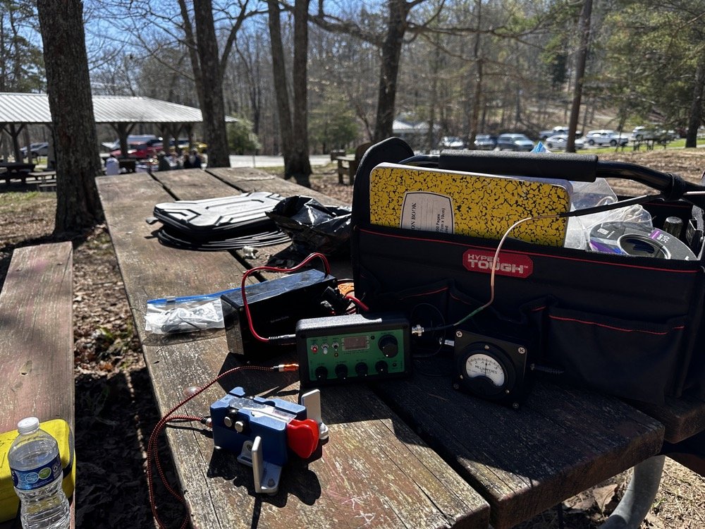
POTA station consisting of the Penntek TR-35, homebrew “S” meter, homebrew powerpack with speaker, Begali Traveler CW key and Relianca Antenna wtih ABR Industries Coax
Murphy’s Law at Work during a POTA Activation
That’s right, I made about 30 contacts while the QRMing op was actively trying to sabotage my activation. lol. So while this was going on, there was another “storm” brewing in the background… the lawnmowers had arrived…

State park grounds keepers doing lawn maintenance.
They had been in the distance, but at this point they were starting to get closer and closer… At this point I am starting to think that these guys have been hired by the guy messing with me on the air! It was like they had been signaled or something. Just about the time the QRM vanishes, they show up!ll, to start with they were mowing over on the far side of the area so it was mildly annoying but not a real problem for my operating…but then…
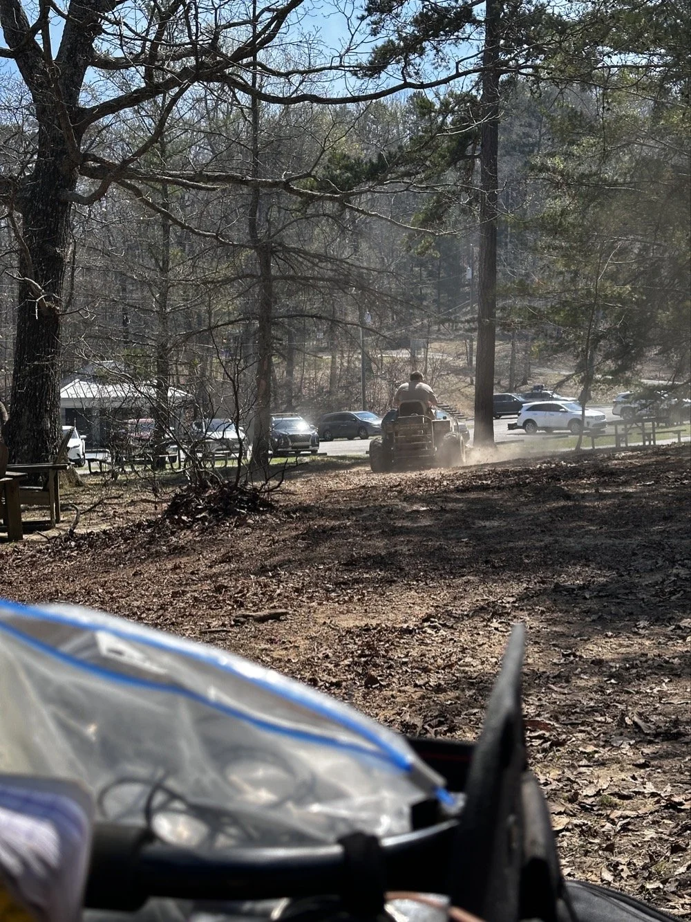
State park employee doing lawn maintenance while I activate POTA at US-2169 Cloudland Canyon State Park.
You guessed it, they felt it imperative to cut the dead leaves in the picnic area RIGHT BESIDE ME!!! Do you see any grass in that site?? I sure didn’t, but he sure was mowing it! Good grief, this is starting to get out of hand at this point and the sound of the engines was so loud that I had to resort to ear bud headphones to be able to hear. This did mitigate almost all of the noise from the mowers but it didn’t do anything for the dust cloud they were stirring up. Good grief.
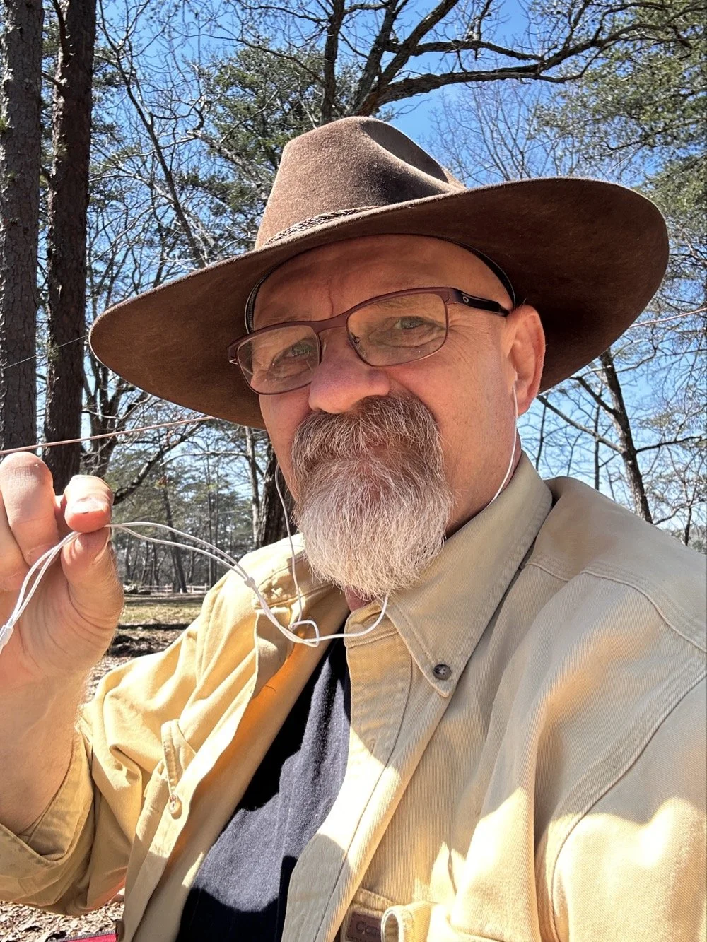
David - WK4DS resorting to headphones due to high noise in the local environment during POTA at Cloudland Canyon State Park
By this point I had almost 80 QSOs in the log so I set a goal of getting 80 counted QSOs to go towards my goal of 10,000 which meant accounting for the dupes in my log, of which there were many today. You see I had been there for several hours at this point and some stations had wandered by me a couple of times. I know I worked one station 3 times today, but so is life sometimes. I no longer tell people I have them in the log, I automatically assume one of two things have happened.
The first one is that I could have gotten someone else’s call wrong and therefore I now have the legitimate call on the hook at that moment. (very possible with my poor hearing at times) The second is that they simply don’t realize I have them in the log. So I work them again and log it again and simply let HAMRS record it as a dupe and move on with life. It doesn’t hurt anything to log them again, other than the time it takes, so I simply complete the QSO as if it was the first time. No harm, no foul.
CW and North America came in clutch for this POTA Activator today!
Today saw me work over 80 calls and of those exactly ZERO were outside of North America. I worked a couple of Canadians but other than that, the rest were US operators only. Not a single DX station at all. It could be one or more of several factors I guess. I did put over 80 calls in the log for today and that is a great day despite all the various things that attempted to stop me. haha. In the end, it was still a wonderful day and I had a great time with my tiny little Penntek TR-35, my Begali Traveler CW Paddle and the Reliance EFHW 40 meter antenna. What a great little setup! Portable, light weight and best of all, it works! What do the old timers say? “Five watts and a wire…” Yeah, it will absolutely work if you will go when the bands are open and just try…
You can help support this website by using these Amazon Affiliate Links:
QRP/Portable Radios:
Antennas & Tuning:
CW Equipment:
Power & Accessories:
Organization & Transport:
BONUS ITEMS
72 - WK4DS (David)