WK4DS Amateur Radio Blog
Search Posts
I have a Penntek TR-35 QRP radio and it keeps growing...
So in this installment of how do you make a tiny, compact QRP radio MUCH bigger, I set out to add an S meter to the system! Now were talking!… or maybe more accurately were using CW … since it is a CW only radio. Anyway, I have been wanting an S meter for this little radio for a long time and then when the ham who invented this radio came out with the next generation (TR-45L) it had an S meter!

Pictured above is the new S meter and beside it is the power pack/speaker assembly, and in front of that is the Penntek TR-35 radio.
Now to be fair, I do have this radio kitted so that I can travel with it very efficiently. I have a kit that has everything I need, but nothing in the way of “frills” and this kit works great. It is small enough to pack in my carry-on bag and even has a power pack too. (Not the one pictured in the blog post but a smaller AA battery tray that holds 10 batteries.)
When I set out to add the S meter to the kit, I started looking for something small that I might could build directly into the radio housing. When I looked into how the radio is actually built though, this turned out to be less than ideal. You see the radio is one circuit board and it is connected to the front panel with ALL of those switches and knobs! Who wants to do all that work for a simple S meter install??? Well, as it turns out I would be that guy. The build to add the S meter as a stand alone part of my little kit was a lot more work than I thought it would be and then there was the trouble shooting and such… lol. Such is life and I now have a really cool, vintage S meter for my tiny station that I am putting together.

The S meter project I chose to build is brilliant to be quite honest. I am not sure who designed it first but I found the schematic on SeekIC.com and proceeded to build it based on this print, substituting parts as I needed due to what I had at hand. Since I did this, it took some experimenting to get the meter to read like I wanted as the final amplifier stage needed the gain adjusted and since I didn’t have a pot big enough, I had to swap resistors till it worked… but it worked. Sadly, I didn’t document the build at all, nor did I bother to even take photos of the internals for some reason, but suffice it to say that I am happy with the result.
Below is my heavily noted printout of the circuit from SeekIC.com. I initially built it without thinking about what was happening and it worked very poorly. This is my fault as I should have looked at the circuit more closely and realized what was going on and that I was misreading things in several places. The three resistors that have the arrows now have the decimal drawn in them. When I first printed the schematic so I could take it to the shop to build it, the decimal points didn’t show up and this meant I thought these resistors were 10 times larger values that what was supposed to be in these locations. This made for some really strange wave forms and the output only going up to .2mA on the meter with VERY strong signals on the radio… I knew something had to be wrong so I started looking at the circuit and figured I had some trouble from my substitution of the two transistors so I looked there first. That was when I noticed the voltage divider for the base of the 2N2222 (this is what I used instead of the 2N4401) was way off for a simple emitter follower amplifier. Then I really looked at the print and realized the number spacing was different on some of the resistors. Like the 15K and the “16K” which after looking more closely was actually a 1.5K… Then I went around the print and found two more like this realizing that I had this thing setup to fail right out of the chute. Back to the shop, modify the resisitor values in these locations and try it again.
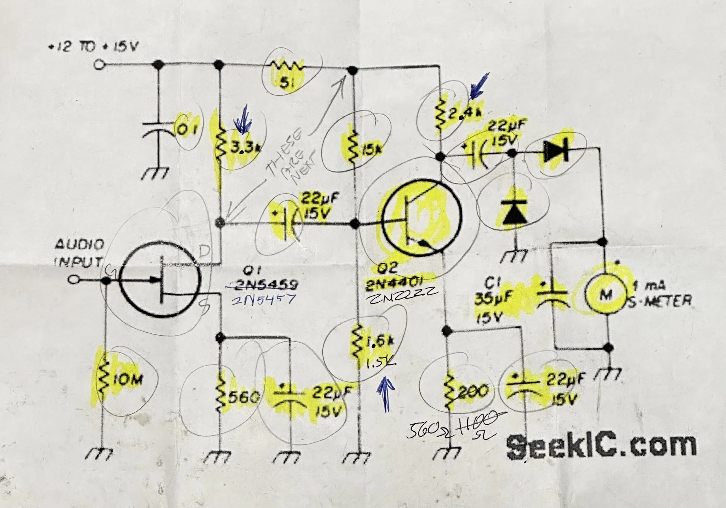
That fixed the low output part, in fact, now I had a lot of output, ALOT! So I once again looked at the amplifier stage and decided to lower the gain on this amplifier from 12 down to 2.18 and see what happens. This worked, but I did overshoot the target a little so I went back and changed it to a gain of 4.3 by using a 560 ohm resistor on the emitter of the 2N2222. This seems about perfect for this little setup now with really strong signals giving full scale deflection but most running in the middle of the scale.
Also of note is that this is a vintage Westinghouse panel meter that reads up to 1mA… So this meter doesn’t load the circuit hardly at all. That was the main reason I chose it. Enough with the new S meter project though, let’s go to a park and put it on the air!

Today I went to Cloudland Canyon (K-2169) and setup by the canyon at my favorite table when the weather is nice. Then I strung up my Reliance Antenna 40m EFHW and connected it to my radio with a piece of ABR Industries coax. Before hoping on the air though, I put another of my recent projects to use, the QRP Guys SWR/Wattmeter kit. I built out the small kit for it with a water tight storage box, a small BNC coax jumper and the instructions should I need them for some reason. It runs on a simple coin cell and works like a charm. It is a great kit if you are looking for something that will handle up to 10 watts like I was.

This thing is a breeze to put together, even the little toroid transformer was pretty easy to build actually. So don’t let “winding a toroid” hold you back, it isn’t that tough to do and the reward is totally worth it.
I checked the antenna and it had less than 1.5:1 SWR on 40, 20 AND 17 meters! I was stoked to see 17 meters was also good to go. This must be something to do with the 20 meter bandwidth, I should have taken the nanoVNA with me to the table (it was in the truck) but I didn’t want to spend a bunch of time on it. I wanted to get on the air and make some contacts!

I have really come to love these cable built by ABR Industries out of Texas. They make all sorts of cabling, but for me, these with the common mode choke built into the cable is a god send. It allows me to simply put up the antenna without worry of RF getting back into the radio and causing me problems from my… less than perfect… antenna installations. When activating POTA parks there is not always a perfect place to install an antenna so you end up with all sorts of stuff on the air and it is possible to have poorly matched impedances on your antennas. The ferrite beads help keep this problem to a minimum.

This little antenna is actually quite long. Approximately 65’ (give or take as I don’t remember right off) and I strung it up into the tree in the photo below. I am pointing out the location of the end where it went to the tree from where I threw my line. It also started at the “radio end” about 15’ off the ground as I strung it over a tree limb at the table to get it off the ground. This puts the whole antenna elevated above the grade somewhat and I want to say it helps as you can see by the logbook below.


60 contacts in one outing, QRP, with decent band conditions will fill your heart with joy. This was a fun afternoon and I plan to do it again soon.
72
WK4DS