WK4DS Amateur Radio Blog
Search Posts
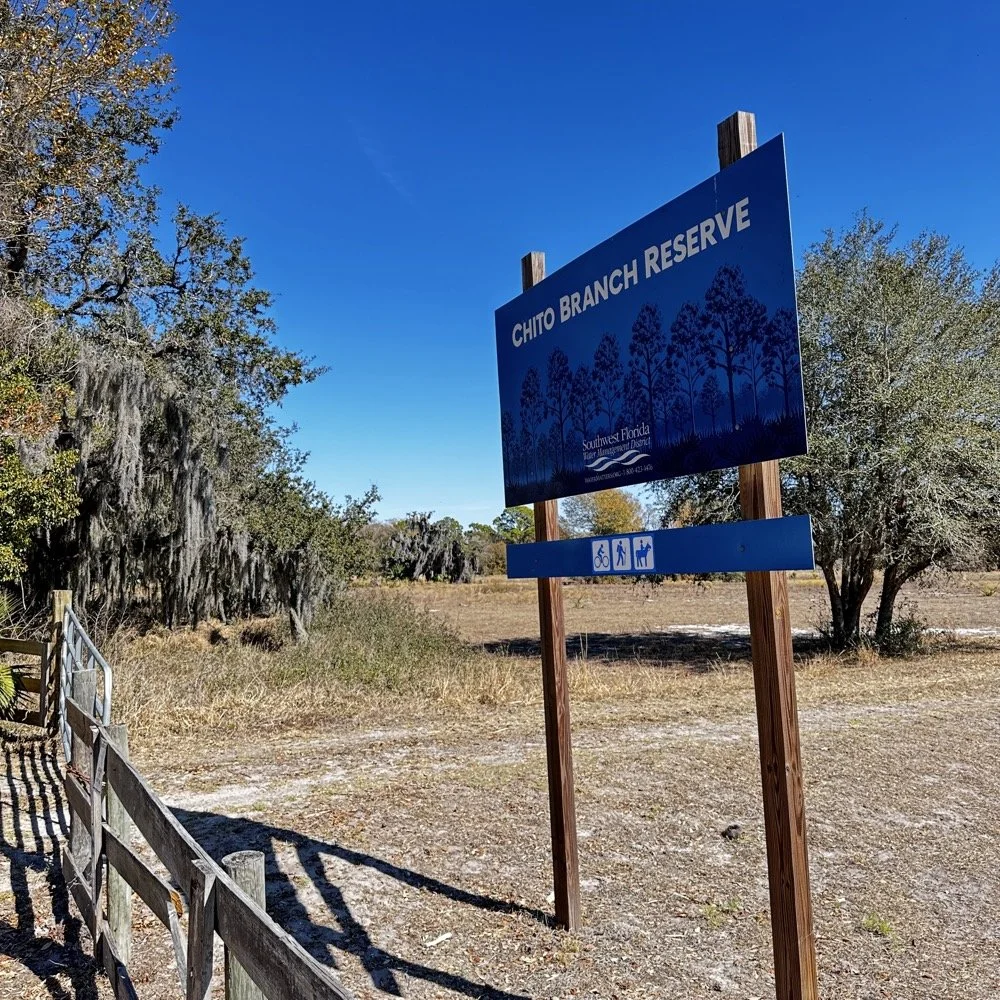
Chito Branch Reserve: First FT4 Contacts, Meeting a Fellow Park Hunter, and the Quest for 1000
Doug's been activating Chito Branch quite a bit lately, and if I'm being honest, we seem to be in a friendly race to see who hits 1000 contacts from this park first. Spoiler alert: he's winning. But it was great to finally shake hands with someone who understands the appeal of spending beautiful Florida mornings in a park with Spanish moss hanging from the trees, headphones on, working the world.
February 10, 2026 • US-5524
Sometimes the best part of a POTA activation isn't the DX you work or the pile-ups you run! it's meeting another operator face-to-face who's been chasing the same goals you have. Today at Chito Branch Reserve, I finally got to meet Doug, KQ4SXW, in person.
I finally got to meet Doug, KQ4SXW
Doug's been activating Chito Branch quite a bit lately, and if I'm being honest, we seem to be in a friendly race to see who hits 1000 contacts from this park first (well, between us at least). Spoiler alert: he's winning. But it was great to finally shake hands with someone who understands the appeal of spending beautiful Florida mornings in a park with Spanish moss hanging from the trees, headphones on, working the world.
The Setup
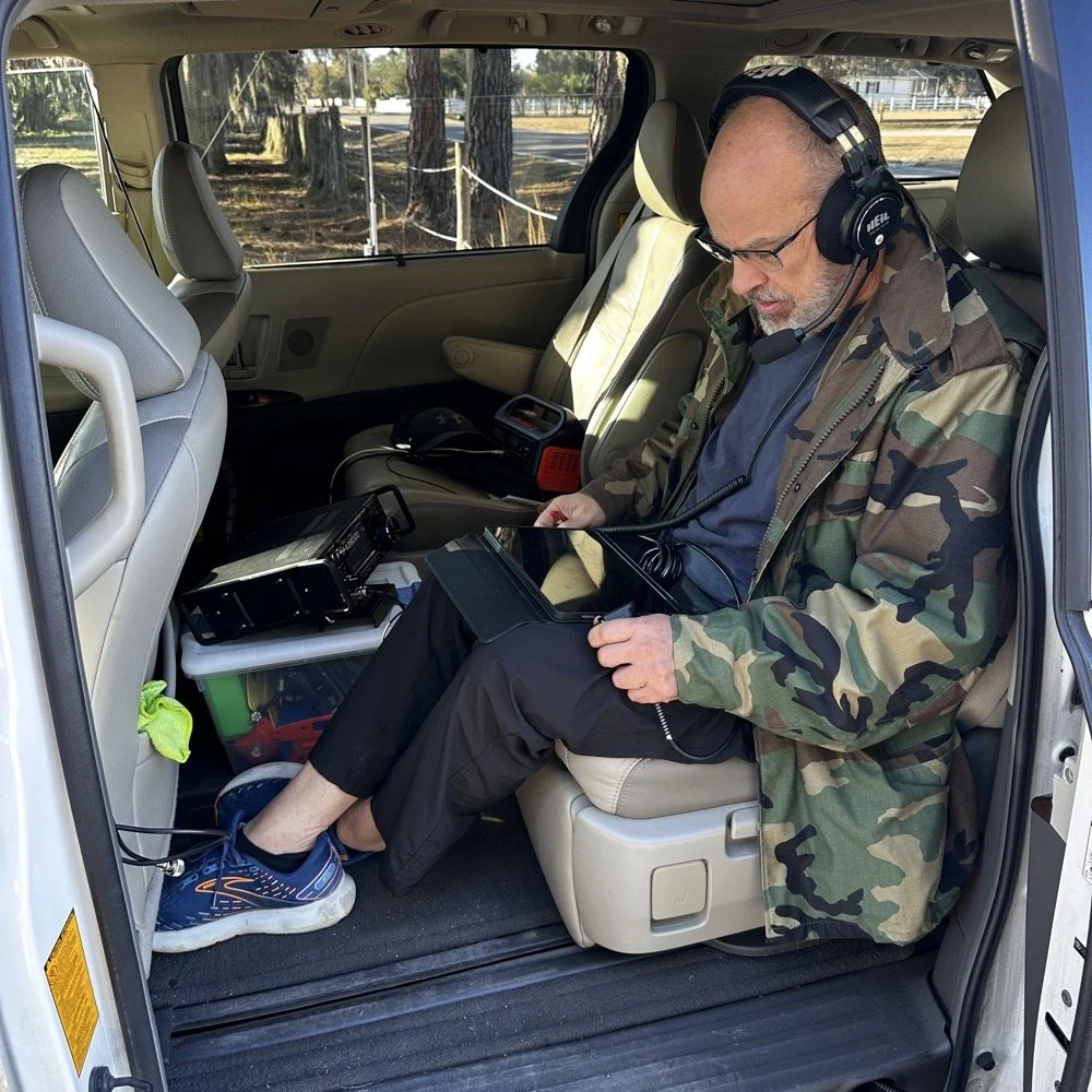
I rolled into Chito Branch mid-morning with my usual portable arsenal. The park is close to where I'm staying in Tampa, which makes it an easy choice for activations, and I've been systematically building toward that 1000-contact milestone. As of today, I'm sitting at 769 QSOs logged from US-5524, so I'm getting close.
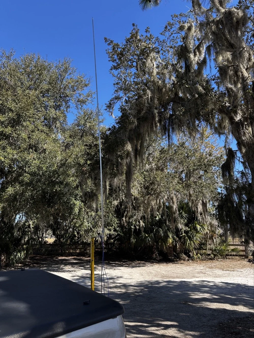
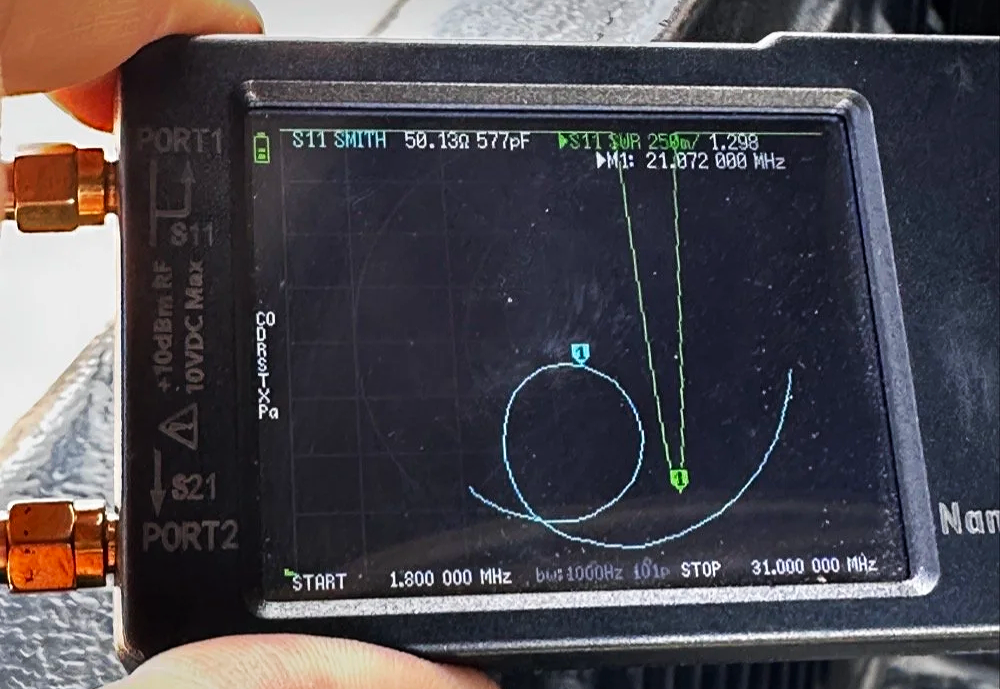
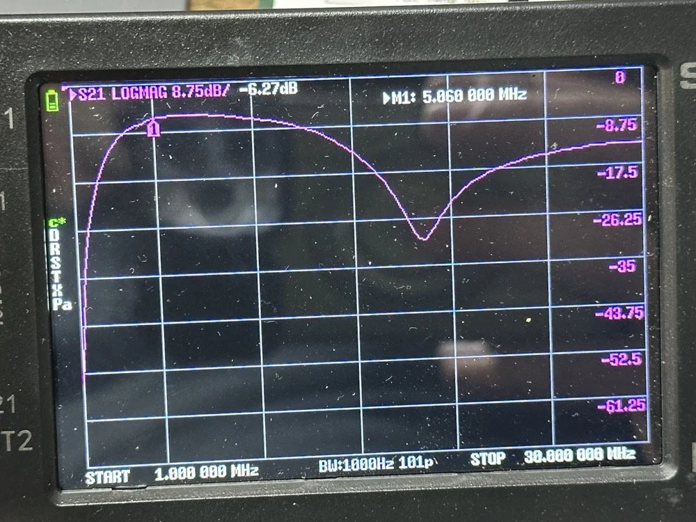
For antennas, I ran my 1/4-wave vertical with two counterpoise wires, tuned for each band. Simple, effective, and quick to deploy. I use the nanoVNA to utne the antenna with. As you can see in the plot above, I get it to something less than 1.5:1 SWR and call it good, I have found that if I get it to that level that I dont have any trouble making contacts at all. I have done OK with the SWR higher in the past…much higher actually, but it is a lot tougher to make contacts like that.
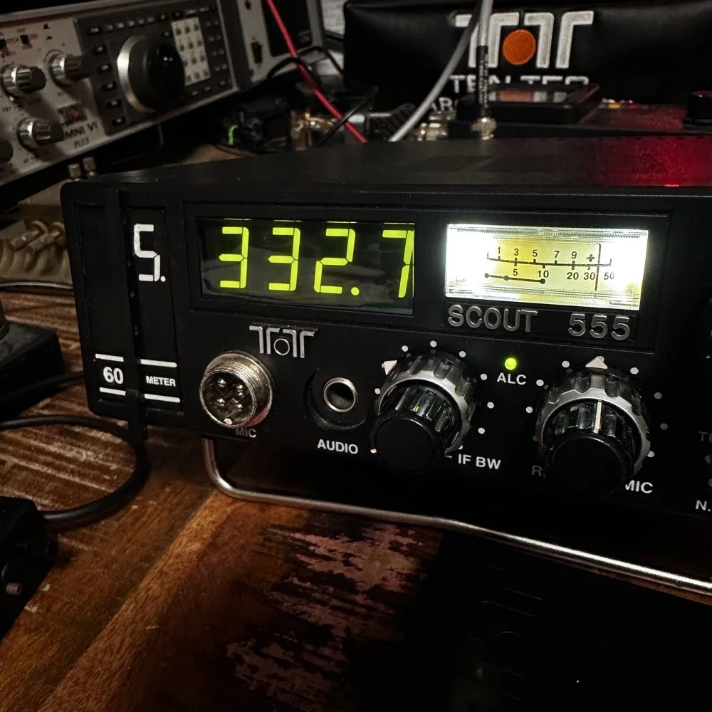
The main rig was the sBitx V3 from HF Signals for digital modes, and I brought along the Ten-Tec Scout 555 for some 15-meter CW work since the bands were looking promising.
Speaking of which… let me tell you about my grid square insurance policy.
A Sticky-Note Solution to a Real Problem
If you operate FT8 or FT4, you know that your grid square locator needs to be correct. It matters for awards, for logging accuracy, and frankly, for not looking like you don't know what you're doing. Recently, I completed an entire activation with the wrong grid square set in the software.
Not ideal.
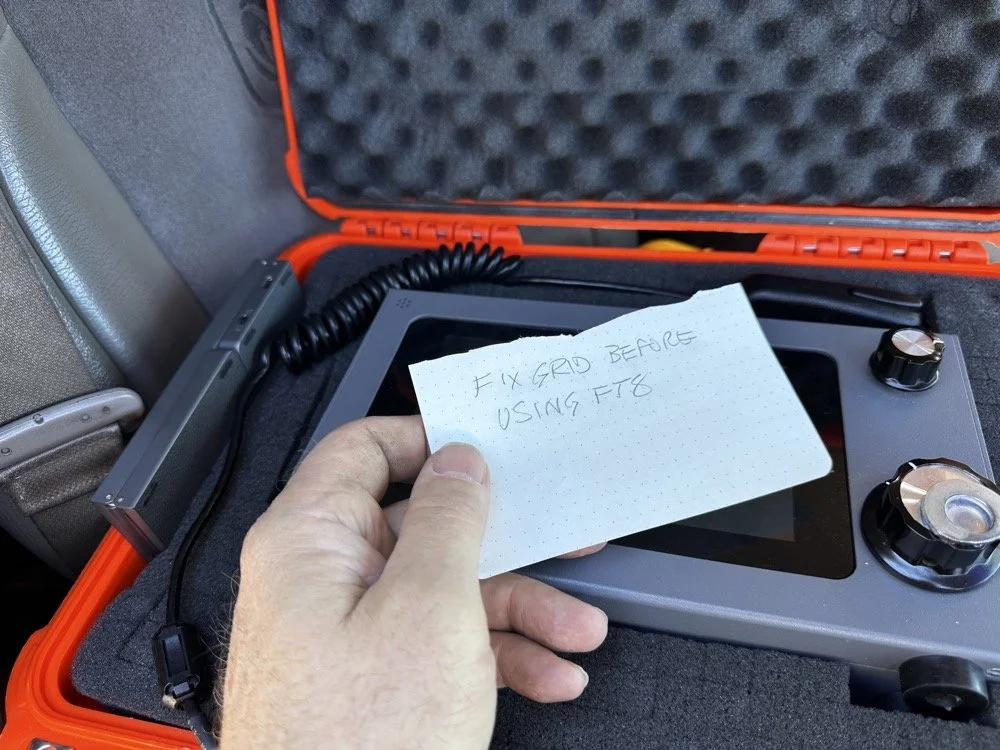
Sometimes the best solutions require the simplest answers…
So I came up with a foolproof solution: I now keep a note in my radio case that says "FIX GRID BEFORE USING FT8." It sits right on top of the sBitx when I open the case, impossible to miss. I also store the Bluetooth keyboard in the case with the radio so I can easily update the grid square in the field without fumbling around with the tiny on-screen controls.
Is it a high-tech solution? No. Does it work? Absolutely. Sometimes the best fixes are the simplest ones.
Starting with FT8 on 20 Meters
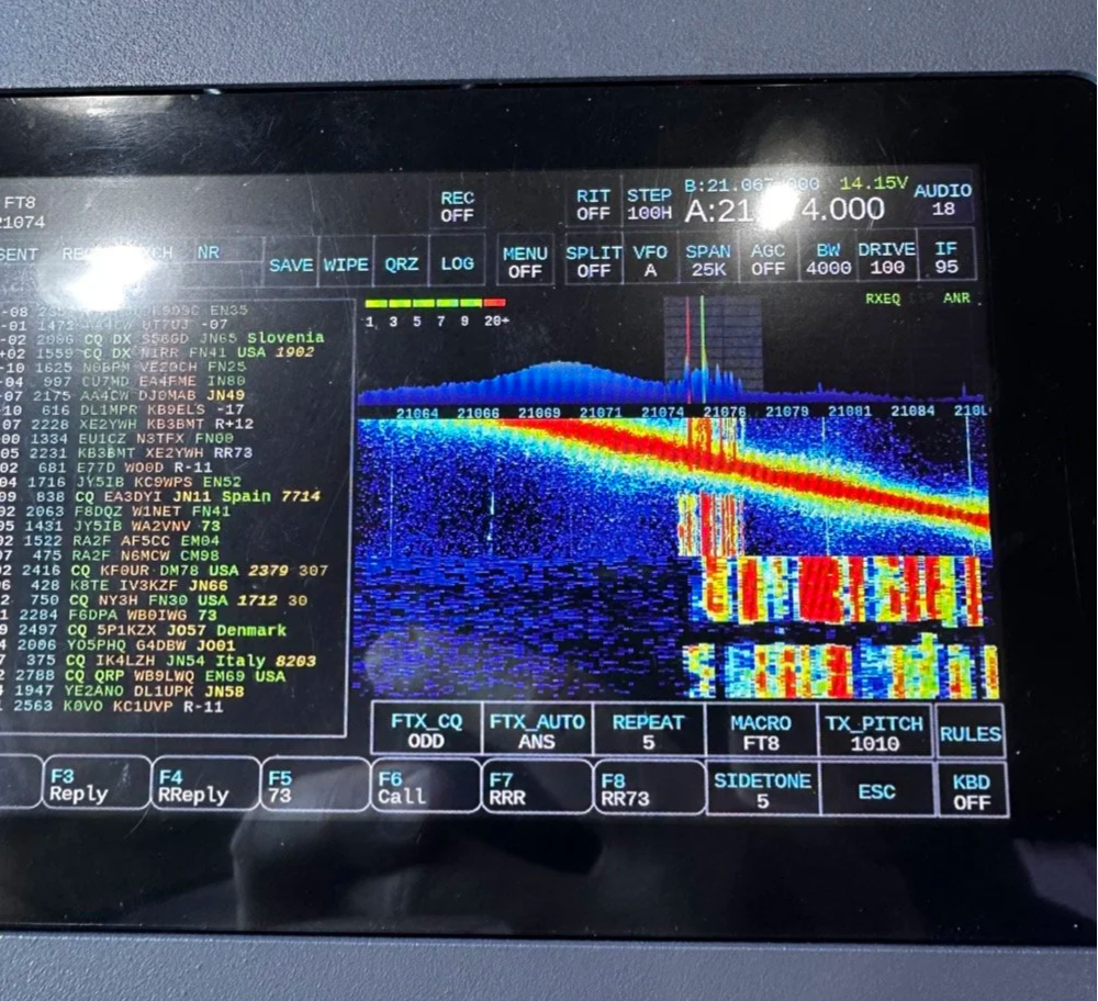
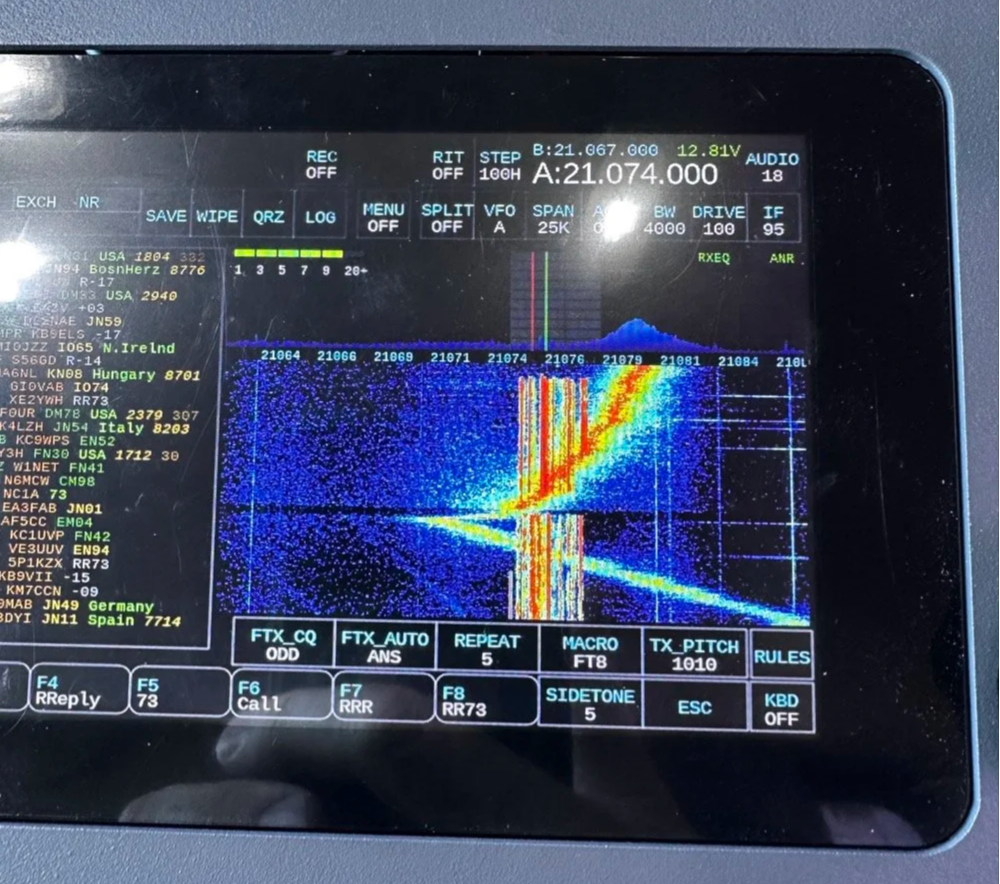
After getting the sBitx fired up…with the correct grid square, thank you very much… I started the activation with FT8 on 20 meters. I spotted myself on POTA and the responses started rolling in. There's something satisfying about watching those waterfalls fill up with decodes and seeing callsigns appear in the queue.
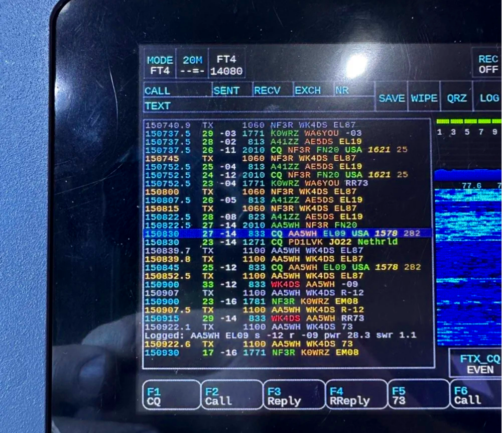
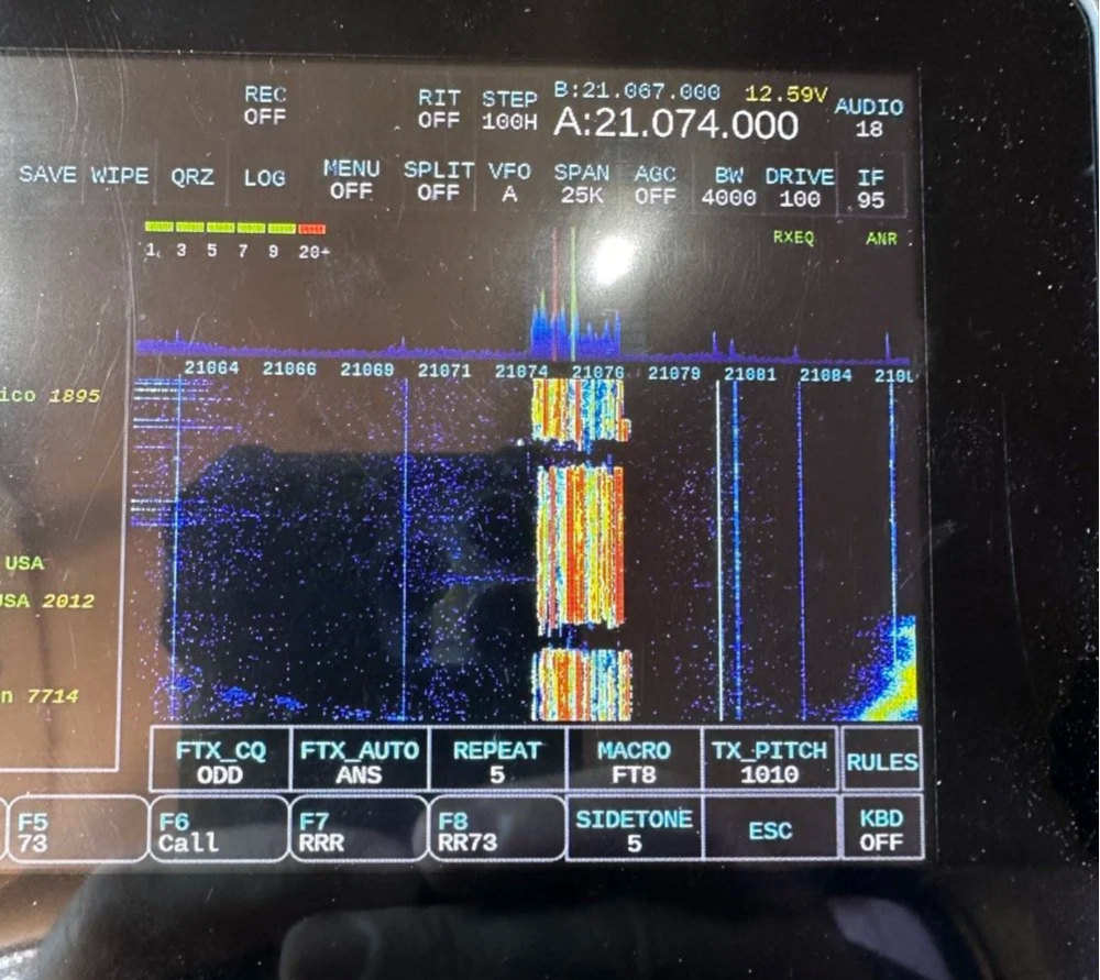
My very 1st FT4 QSO with the sBitx!
I worked through a solid session and logged about 18 contacts on 20-meter FT8. The band was cooperative, signals were good, and the activation was off to a strong start. Something to note about my sBitx V3 is that it has developed a sort of internal noise on 20 meters that lingers in the CW portion of the band. It goes down in frequency as the radio warms up so I have to figure out what is causing this problem when I get home the next time. I have it on the list right next to fixing my microphone pre-amp circuit for proper operation as well.
First FT4 Contacts at a POTA Park
After the FT8 run, I decided to try something new: FT4. I've run plenty of FT8 from parks, but FT4 was uncharted territory for me in the field.
FT4 is faster than FT8, cycling every 7.5 seconds instead of 15, which makes it great for contesting or when you just want to move quickly through a pile-up. I updated my spot on POTA again and started calling CQ. To be honest, I had used it a little in the shack before with no luck so I didn’t hold my breath today, To me utter surprise, I saw a QSO forming in the call feed on the left! Then it finished and logged it! I hurriedly got out my phone and snapped a quick photo to share with you guys…
First contact: AA5WH on 20 meters. Clean decode, solid signal, contact in the log. Then I switched to 15 meters and worked N1KLF. Two FT4 contacts, my first ever from a park, and honestly? I was pretty stoked. There's something satisfying about trying a new mode and having it just work.
15 Meters CW Was Alive
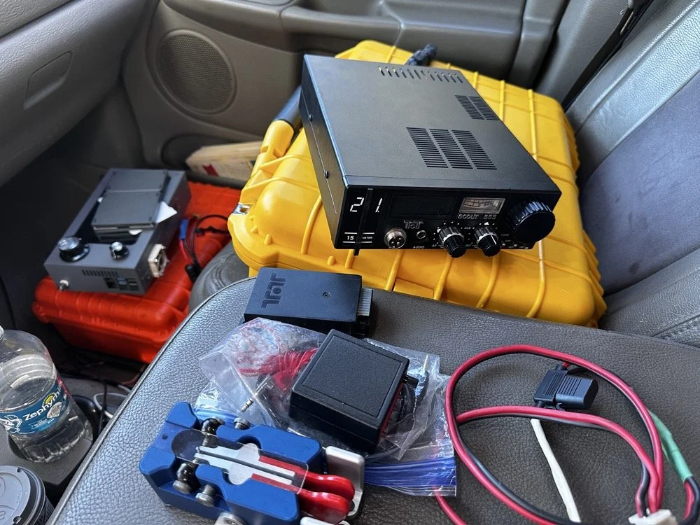
The TenTec Scout 55 is pictured with the HF Signals sBitx V3 where I was changing over to CW after working 2 digital modes today.
After the FT4 session, I switched gears completely. I packed up the sBitx and pulled out the Ten-Tec Scout 555 for some CW on 15 meters. The band was in great shape, though there was a bit of QSB rolling through. I got the radio all connected up to the keyer and then plugged in the Travler. My Begali Traveler key has become one of my favorites—smooth action, compact enough for portable ops, and it just feels good. It is sensitive, but that is how I use my keys, I prefer a light action myself and that is why I made my own paddles back in the day. N3ZN (Tony) and I2RTF(Pietro) make some of the nicest keys around at the moment and I am glad I have one from each.
DX Contacts That Made It Worthwhile
Right out of the gate, I snagged some DX that made the whole activation worthwhile:
EA4MZ in Spain
DD1LD in Germany
YV1GIY in Venezuela
PY5XT in Brazil
Four different countries, all on 15-meter CW with 40 watts and a telescoping 1/4 wave vertical, what more can you ask for? Days like this remind me why I love this hobby. Some of them were a little on the weak side but the Jones filter in the Scout actually helps if you open it up instead of closing it down. This seems counter intuitive, but opening the filter up just ever so slightly will let a lot more of the other operators signal though and just a little of the background noise, it is almost like having them turn their power up 50% or something, if you have not tried it with your Scout 555, I suggest you find a signal you can barely hear and give it a shot.
43 QSOs and Counting
By the time I packed up, I had 44 contacts in the log, though one turned out to be a duplicate, so 43 that counted. Not a huge number, but solid for a few hours of casual operating across three modes (FT8, FT4, and CW) and two bands.
Meeting Doug in person was the cherry on top. It's always good to connect with like-minded people in the hobby, especially when you're both chasing the same quirky goals. A thousand contacts from one park? Yeah, it's a bit obsessive. But things like that are what makes it fun.
SIDE QUEST TIME:
I ran into a unique problem today that is worth mentioning here. I was charging my computer with an inverter that I have wired into the cab of my truck. I was also running the truck so I could power the inverter and charge the computer as well as the sBitx V3 at the time. Well it turn out that I have some issues with this inverter that need resolving. The next few photos show the RF hash that this inverter is producing when under load! It is unreal how bad it was, I couldn’t believe all I had to do was simply shut off the engine and unplug the power cord from the logging computer and it went completely away…
The above photo shows the hash of running both devices on the inverter with the engine running on the truck.
The next photo shows what happened when I shut off the truck and unplugged the computer.
The last photo shows what the band looked like once I went around to the other side of the truck and powered off the inverter completely. This goes to show that you need to check these things if you plan to use RF devices like radios in the presence of RF trash generating devices like this inverter… Better inverter coming up!
END SIDE QUEST
Hit me up!
231 contacts to go until I hit the big 1000 from Chito Branch. At this rate, it'll take a few more activations, but I'm not in a hurry. Well, maybe a little… Doug's still ahead of me.
If you're in the Tampa area and see someone set up at Chito Branch Reserve with a vertical antenna and a tablet running digital modes, stop by and say hello. Chances are it's either me or Doug, and either way, you'll be in good company.
**Gear Used This Activation:**
- **Radios:** HF Signals sBitx V3, Ten-Tec Scout 555
- **Antenna:** 1/4-wave vertical with dual counterpoise wires
- **Key:** Begali Traveler
- **Digital Mode Software:** JJ and the sBitx 64 bit Development team version 5.301 (FT8/FT4)
- **Computer:** Dell Inspiron with Linux and HAMRS
- **Accessories:** NanoVNA for antenna tuning
Have you tried FT4 for POTA activations? What's your go-to mode for portable operations? Drop a comment below or find me on Facebook or shoot me an email on here.
What is FT4 and how is it different from FT8? FT4 is a digital mode similar to FT8 but with a faster cycle time (7.5 seconds vs 15 seconds), making it better suited for contests and quick pile-ups.
What equipment do I need for POTA FT4 activations? You need an HF transceiver capable of digital modes, a computer or tablet running WSJT-X software, an interface between your radio and computer, and a suitable antenna for your chosen bands.
Where is Chito Branch Reserve located? Chito Branch Reserve (US-5524) is located in the Tampa Bay area of Florida and is part of the Southwest Florida Water Management District.
How many contacts do you need for a valid POTA activation? You need a minimum of 10 QSOs to qualify for a valid POTA activation.
You can help support this website by using these Amazon Affiliate Links:
QRP/Portable Radios:
Antennas & Tuning:
CW Equipment:
Power & Accessories:
Organization & Transport:
BONUS ITEMS
73,
David WK4DS
![Ten-Tec Scout 555 60m Band Module: IF Filter Redesign & Final Testing [Part 4]](https://images.squarespace-cdn.com/content/v1/5d17806ce65eba00011667cb/083bf6b4-e926-4837-8a07-9c333538b44c/IMG_1543.png)
Ten-Tec Scout 555 60m Band Module: IF Filter Redesign & Final Testing [Part 4]
Today saw me finish the TenTec Scout 555 60 meter Band Module Project in the workshop, now it is on to phase 2, testing in the field… I had wanted to rework the filter in the IF stage as it was not great from before. I was able to get a signal out of the radio, but the filter shape left something to be desired…
This is the final episode in my Ten-Tec Scout 555 60-meter band module series:
- Part 1: Initial Conversion and Filter Design
- Part 2: Crystal Selection and Mixer Circuits
Today saw me finish the TenTec Scout 555 60 meter Band Module Project in the workshop, now it is on to phase 2, testing in the field… I had wanted to rework the filter in the IF stage as it was not great from before. I was able to get a signal out of the radio, but the filter shape left something to be desired…
The first chart image is of my filter after I got the radio to work. This is not what a bandpass filter should look like. The lower photo is of a factory TenTec VERY narrow bandwidth 40 meter bandpass filter. Turns out, this is almost impossible to replicate with discrete components that are not adjustable…as you will see. They used two tunable inductors to achieve this filter shape. I almost went to the trouble of adding some trimmer capacitors to mine, but as you will soon see, I felt it wasn’t needed. I soon learned what a filter Q is and why it matters when your trying to build a filter. I used some online calculators to get the component sizes for the filters and after messing around with a couple, I found one of the calculators had came up with numbers that were actually able to be made in my shop.
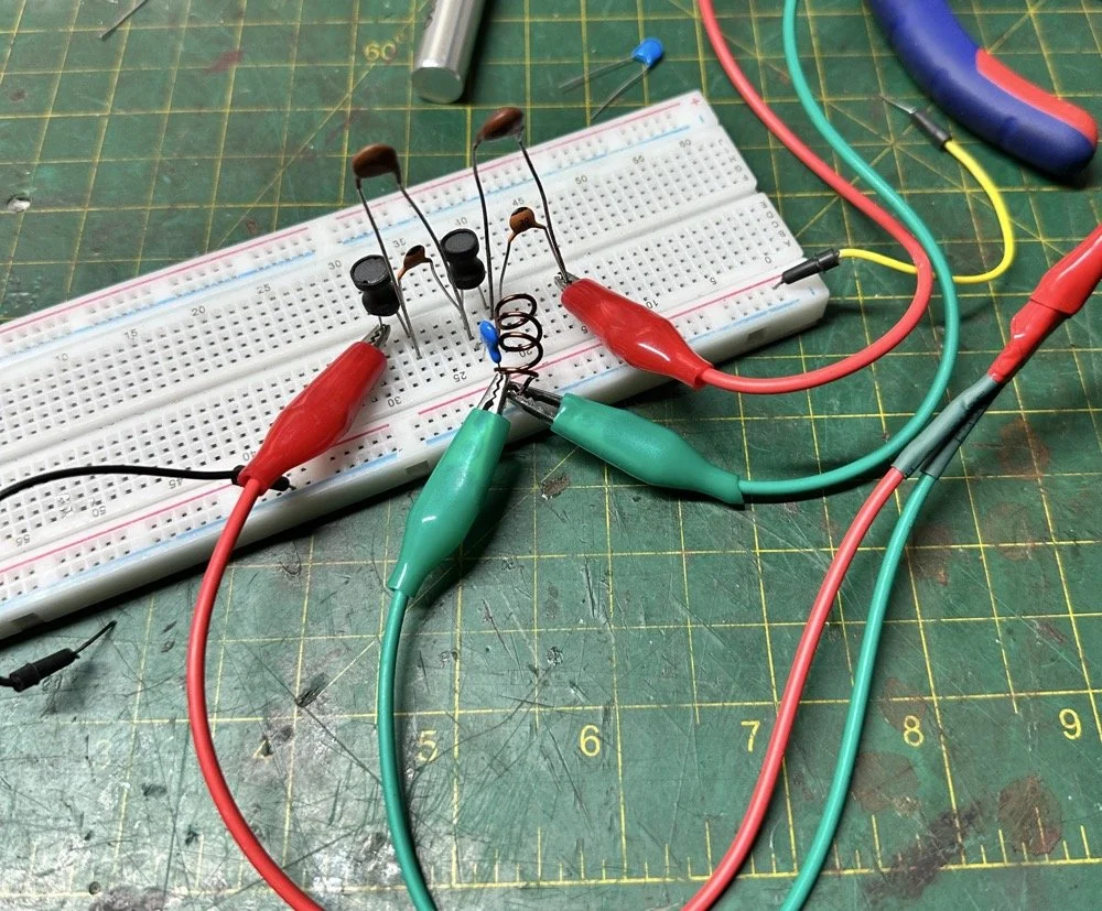
Armed with this information I decide to breadboard this filter first so I could tinker with it before soldering it to the band module circuit board. This, as it turns out, is a terrible idea if you plan to simply transfer the parts to the board and solder it all together. There is SO much stray capacitance and inductance at RF frequencies with a breadboard that you can build up a circuit, but when it comes to making the final item on perf board or Manhattan style, that you WILL use different values.
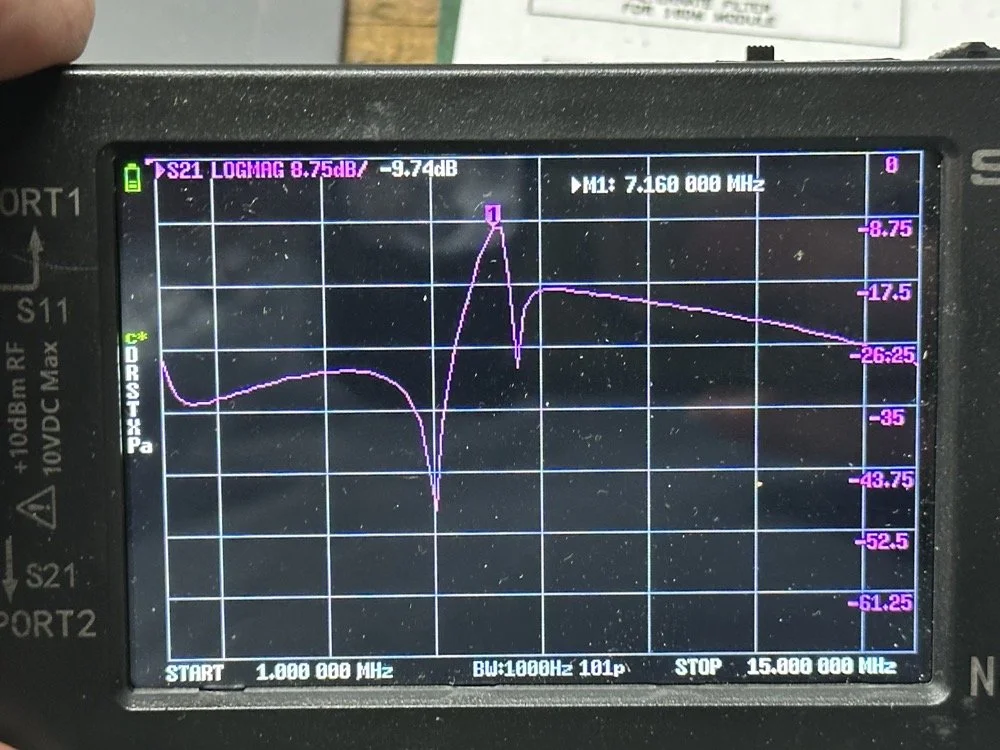
Looks good doesn’t it? Well look at the plot below! It actually looked great! It did have some insertion loss that I was not super happy about, but that plot looks great! Yes, the one inductor is hand made, I didn’t have one small enough in my little kits to work here I so wound one for the job. Notice how long the leads are on those components, that will come into play very soon…
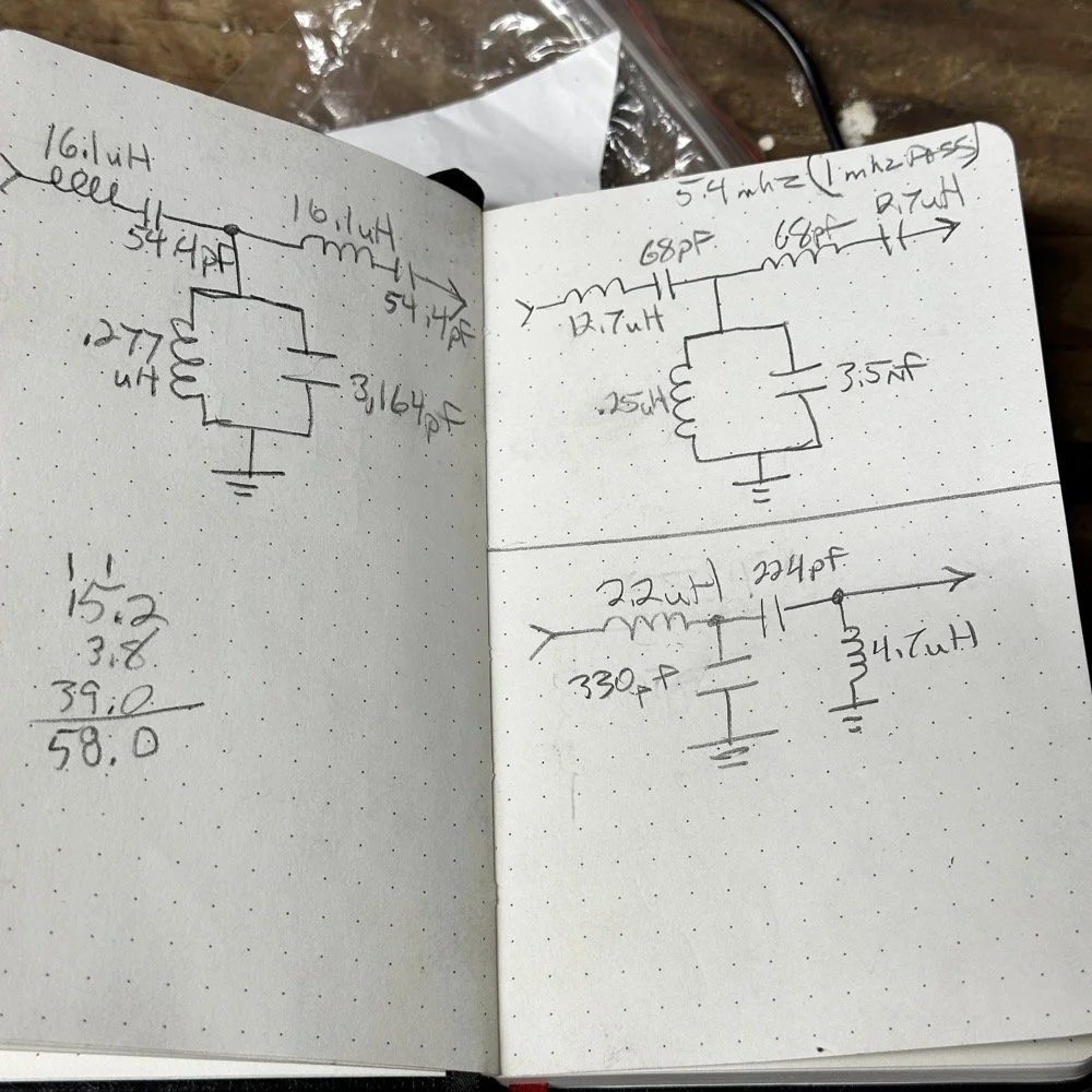
I may have gotten a little aggressive with the passband width… I think it was set to 200khz or maybe 500khz, but it was not much. I think the values I put into the online calculator were 5.4mhz center frequency, 500khz bandwidth and 3 LC stages in a “T” configuration. The bottom line on the chart is -70dB which is unbelievable! This thing was incredible! So I get the 60 meter module out and take it apart and strip out the old filter I had previously built wholesale leaving a clean slate for the new filter…
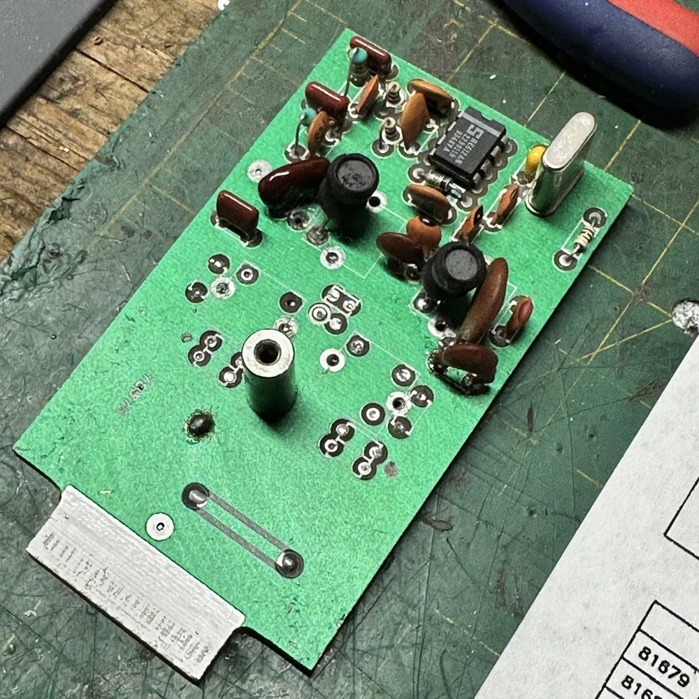
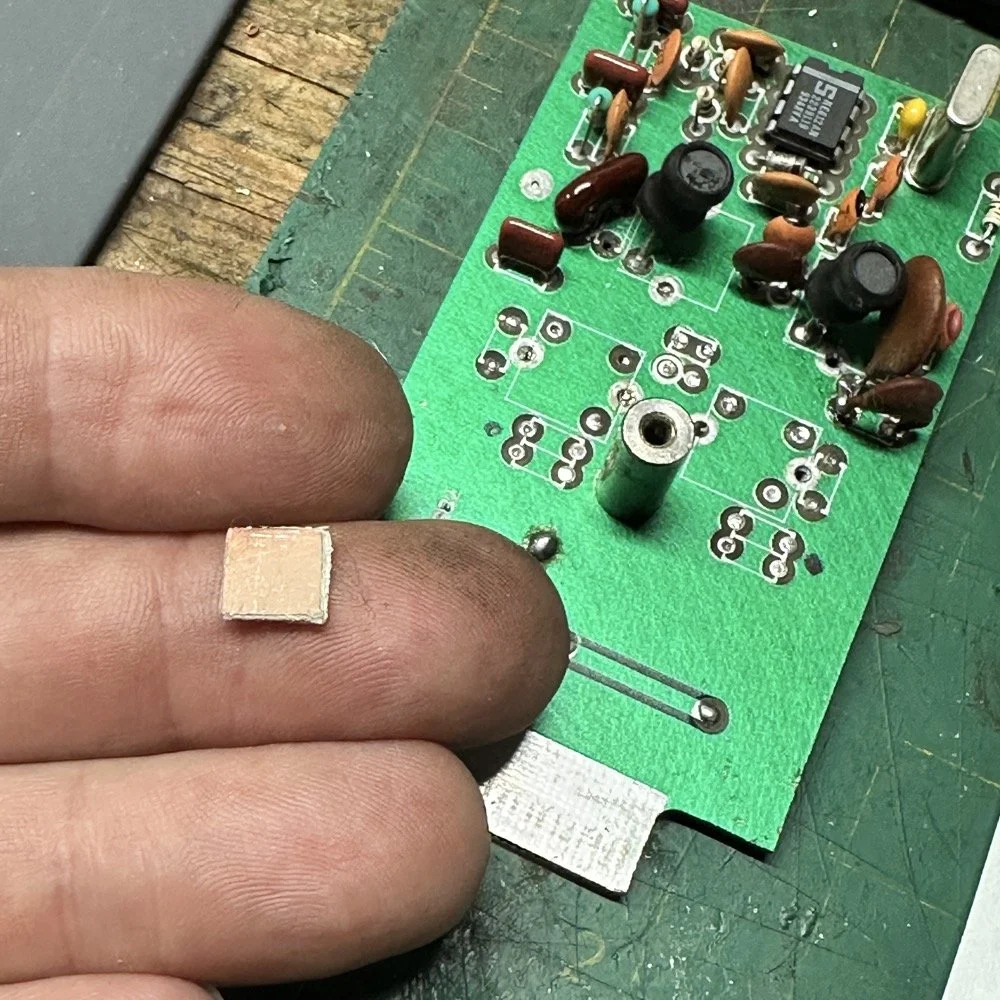
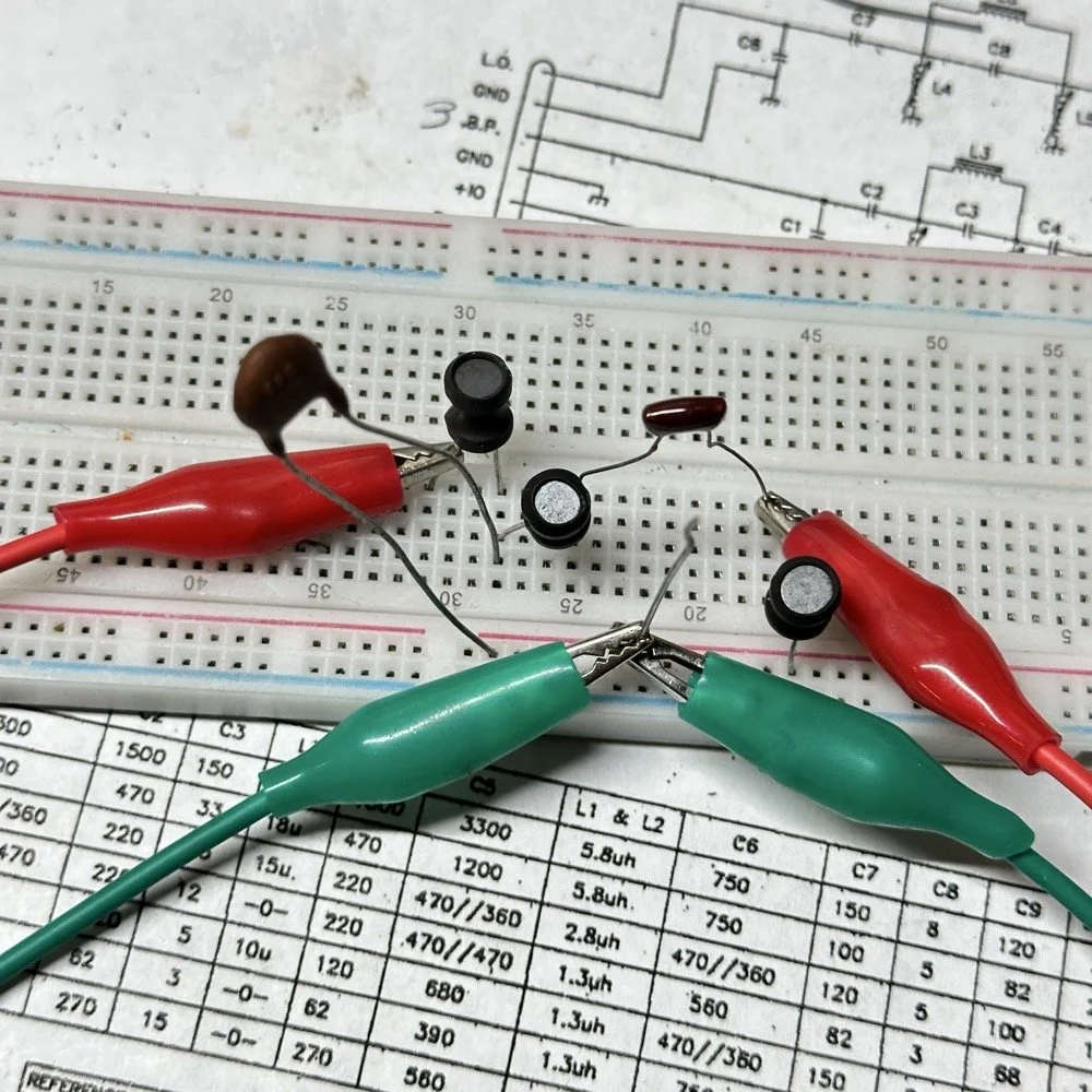
After I had the old filter gone and cleaned up a little, I cut me a pad as the new filter layout and the TenTec layout are different so I wanted to not have to permanently alter the circuit board other then removing the old components. This pad became the central connection point for the three stages. A little hot glue and I was in business! I simply tinned the whole top of the pad so I could land part leads where ever I wanted on it. This worked really well…much better than the filter I am about to build as it would turn out.
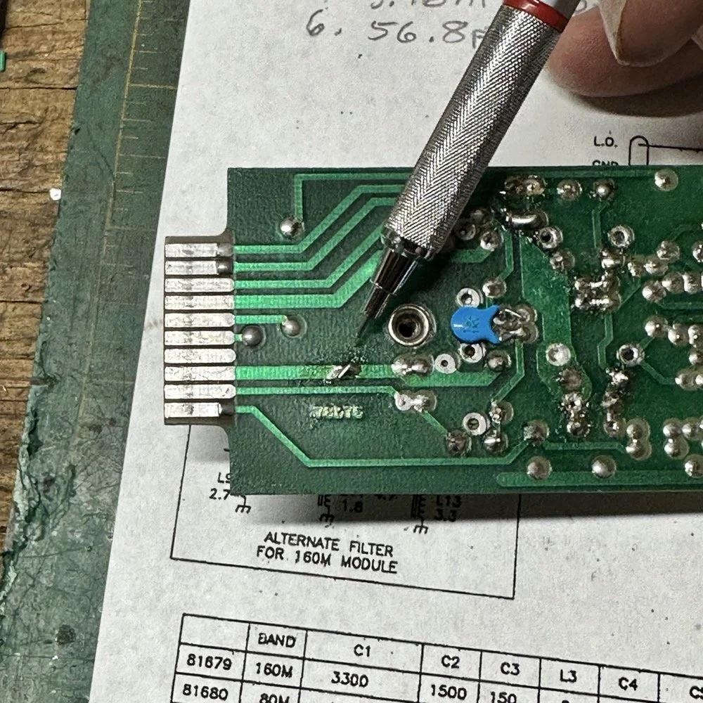
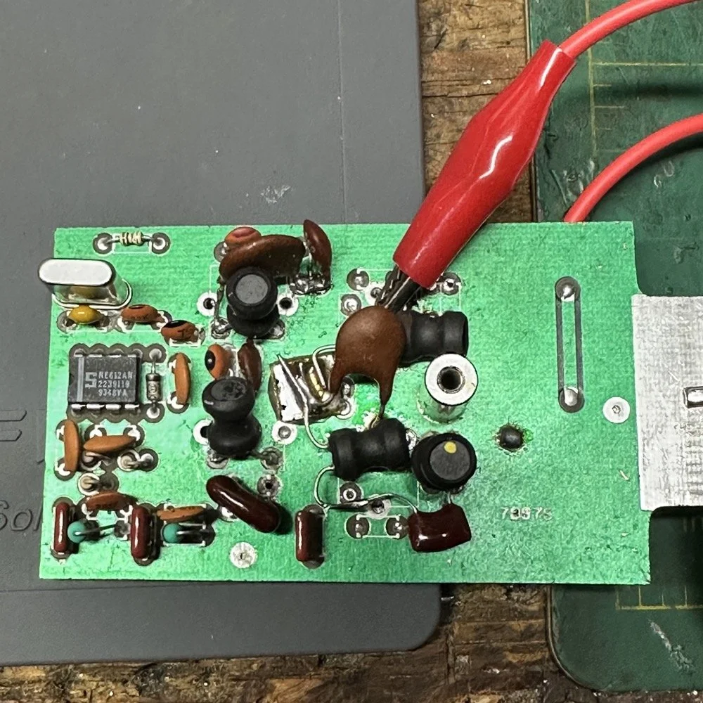
SIDE NOTE ABOUT MODIFYING SCOUT BAND MODULES:
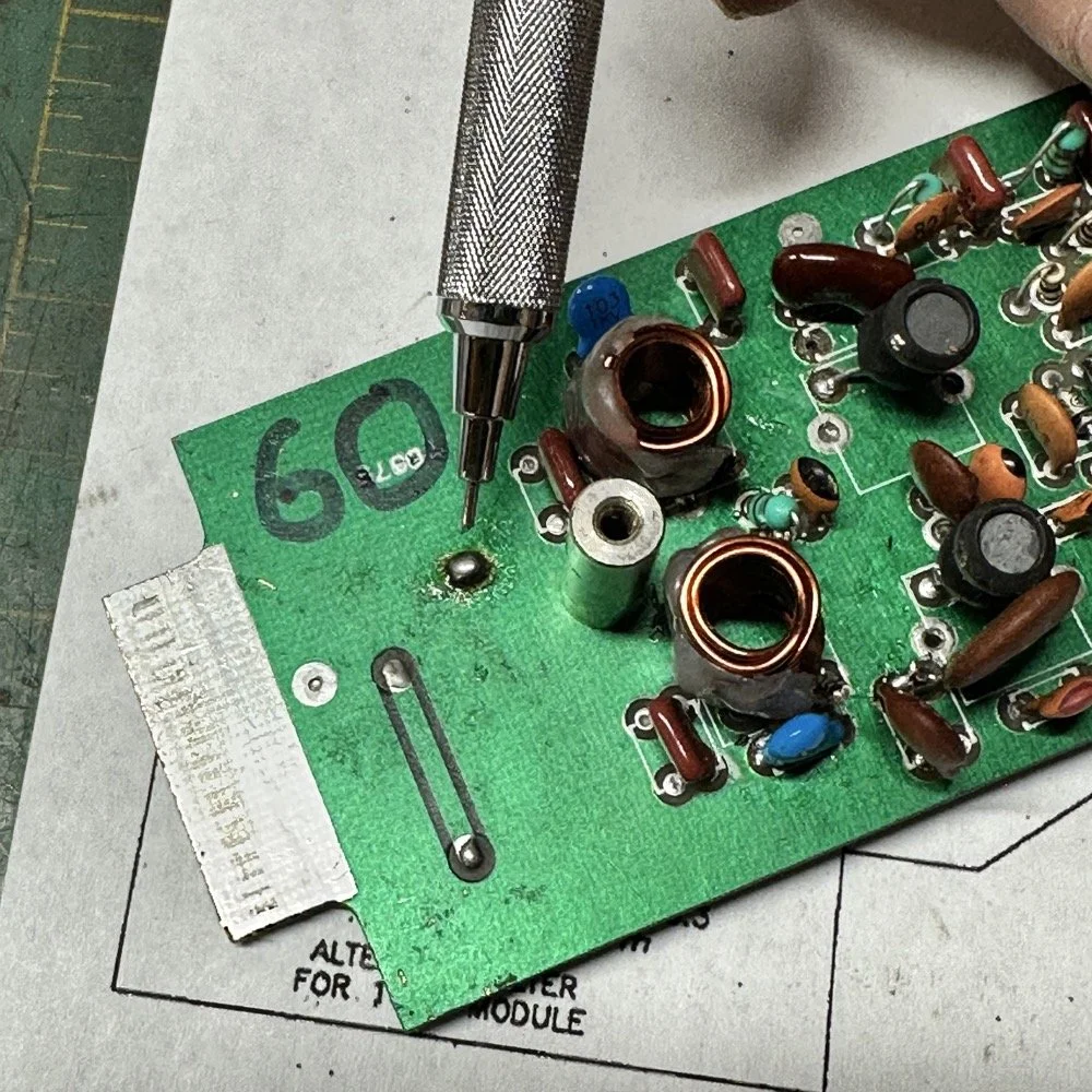
What I am pointing out in these two photos is a home made Via that I added. You see, when you remove the canned tunable inductors from the board, turns out you break the grounds. TenTec decided that since these things were going to be here anyway, might as well use them for something. So they apparently decided to make them connect one ground plane to another in a couple of places on the board. Once you remove the cans, you lose a critical ground path…or two. I took a finger drill and a very small drill bit and drilled a hole from one trace to the ground plane on the opposite side(I am confident these are only two layer boards), then I soldered a bonding jumper wire in the hole so both planes would once again be connected again and all the stuff would continue to work properly. You also get to see the old homebrew filter in the below photo as a bonus.
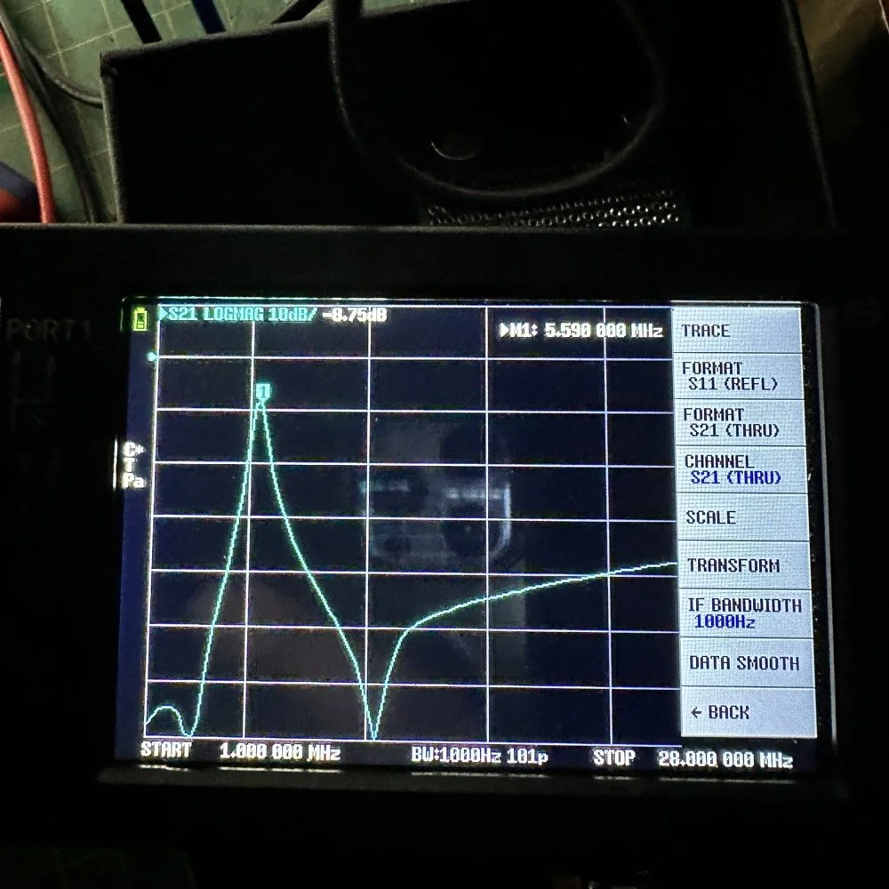
Below is the result of me simply attempting to move the parts over to the circuit board and soldering them in place… What a mess. I started with the exact parts you saw on the breadboard, but when I connected the nanoVNA to the filter I found the center frequency had moved up 500khz! It was now pushing my desired frequency out of the passband!!! I was seeing something like 16dB of loss at the desired frequency.
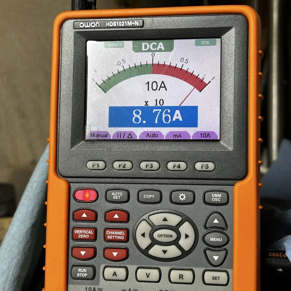
This is the world of ultra high Q passband filters made with inductors and capacitors I guess. Once I removed all the stray capacitance from the breadboarded system, all the capacitor values went down enough to make the filter not usable. That is why you see the mess below, I didn’t have room for the trimmer caps I have on hand so it was good ole trial and error method instead to get the passband in the right spot. To be fair, this mess actually worked, it just had something like 12 or 13dB of insertion loss in the filter which made the output power go way down. I used the amp meter to check it and the current draw on transmit with this filter was 1.8 amps and the current draw with the factory 40 meter band module was 9.3 amps. So I took a break and grabbed some food and went back to the drawing board…
I am going to admit something here that might make some people unhappy with me…I decided to use Claude AI to see what it would come up with for a filter design. I gave it all the parameters I had used earlier and (since it is a chatbot after all) had a conversation about what my goal was. I decided to move the bandwidth out to 1mhz giving me a decent shot at making a working filter without adjustable parts and using only what I had available on site.
This AI model came up with a “T” filter but instead of the center 2 LC components being in parallel, they were in series and so I built it. It tested really bad as far as rejection goes as it only attenuated about 8 or 10dB across the whole band and looked more like a poorly designed high pass filter instead. This did give me some inspiration though. So I went back to the online calculators that are there to figure part values for you and changed my approach. I went to this website and just made a low pass filter and then a high pass filter and coupled them together with an inductor. Why did I choose an inductor? Because all the capacitors I tried kept increasing the losses in the filter output is why. As it turns out, if you attenuate the IF signal in the radio the output power get lowered and the radio goes “deaf”…
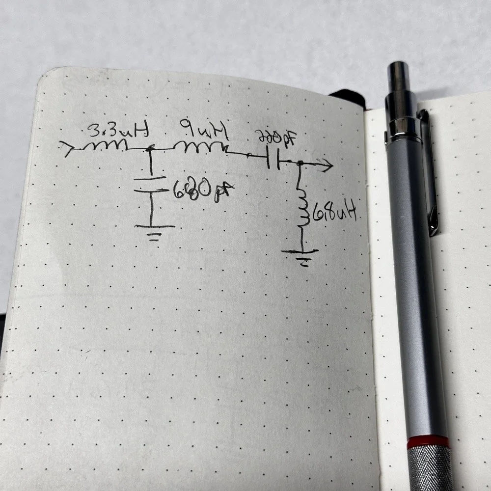
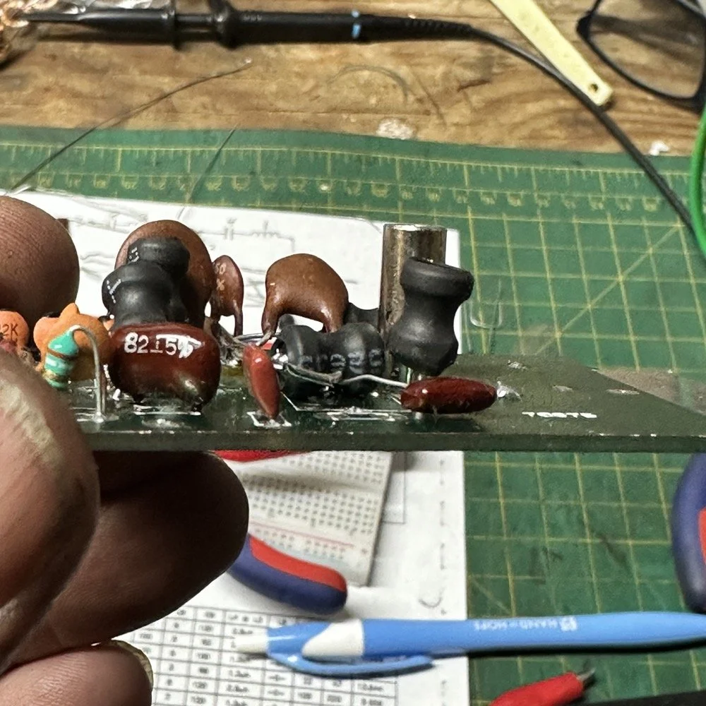
Below is what I came away with finally. Yes, only 3 inductors and two capacitors.
Below is the filter shape for this simple filter design too. It is a lot better than what I started with and I was able to build it with parts that I had available to me at the time. Could the passband be narrower? Yeah, it could, but I am not going to throw too much shade at this filter. This is what ham radio is all about in my book, experimentation. The marker is at 5.64mhz which is 250khz above the highest place I can transmit so I know this filter wont attenuate my signal and the radio will work as it should.
The original values for the filter ended up being wrong, but I simply did what I did in the previous filter build and just used it as a jumping off point and started switching out parts one at a time with different values. This tactic coupled with looking at the nanoVNA to see what the new part did to the filter shape gave me the results you see. At first I didn’t write down what I had done, but it quickly became apparent I needed to note what I had done and so things progressed much more quickly once I did.
The above photo ( bottom of the second page ) is what I started with on this part and the lower photo is what I ultimately ended up with for the actual parts I used to build the filter. You can see where I was trying all sorts of stuff to get a working filter, these are not the only sketches either…
This is what I ended up with ultimately to get the filter shape above. The impedances are wrong, I am sure as I didn’t take them into consideration at all, but the radio is working correctly now (from what I can tell) and transmits almost at full power. Shoot, they could be right and I just got them right by accident, I really don’t know to be honest.
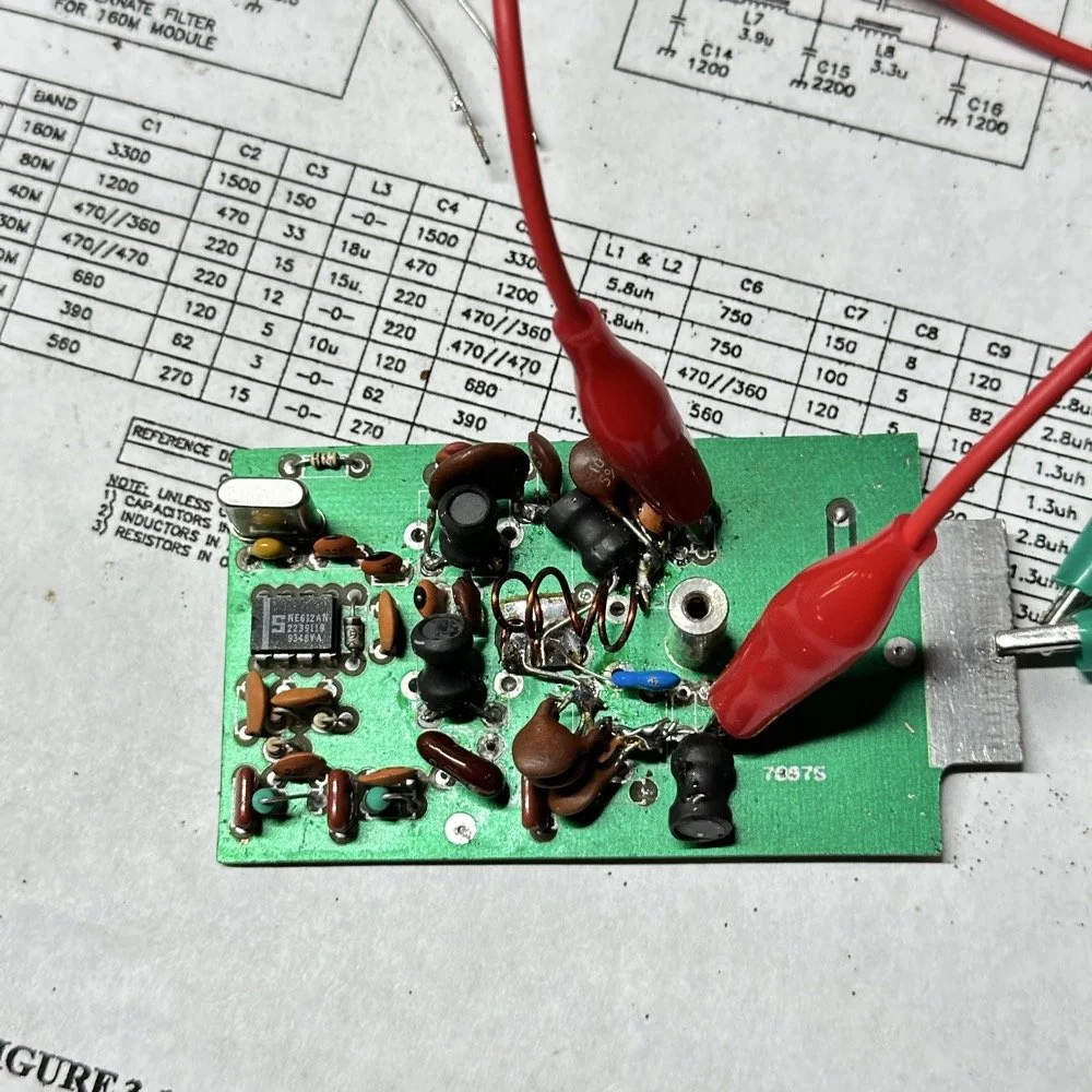
This is the output power draw now for the 60 meter module on the same radio as the 40 meter module previously compared. I can live with that! I checked it when I got into the shack at the house and it is a little over 35 watts into a 1.3:1 SWR load. That will work just fine for me. (Note: The current reading was into a 50 ohm dummy load at the workbench so I don’t know the exact current draw in the shack.) This radio will produce more output power too, I have it dialed back on purpose to about 40 watts for the 20 meter band module that I use with this radio.
This is what the final filter looked like when I was finished building it. This looks a lot better than that mess I started out with above. Not overly complicated and generates a respectable filter shape. The radio sounds good too. So I am happy with this.
Side note about the above photo, I had noticed in my original filter design that the orientation of the inductors made a difference in the filter profile on the nanoVNA so I started marking them with a paint pen to remember the orientation. This filter didn’t seem to care too much about that for some reason but the original cared ALOT.
The side view photo shows something else the I have not mentioned in these write-ups. The filter has space constraints. The filter can not be taller than that metal post or the other circuit board with hit the parts and the parts can not go past the post either as that is the space for the output low pass filter from the other board. So parts count matters…
It feels oddly satisfying to see the finished module and to use it in the shack. All I did last night was listen to some stations having a QSO and how well it could hear them. I also dialed up the webSDR again and listened to myself calling CQ for a bit with no takers on a different channel. I know the radio is working as the listening station in Utah could hear me…
Tonight I hope to find a chance to jump into a QSO with someone and see how it sounds to them.
I hope this has inspired you to do something with your gear whether it be build a kit or modify a device to do something new or different or even to repair something you have that is not working now…shoot maybe you will learn something you didn’t know before! That is what has happened to me on this journey, I have learned a lot about how filters work and what affects them in use. I am starting to understand impedance matching the stages as well as insertion loss. A lot of things I never understood before are now becoming more clear. I also have a much clearer understanding about how the TenTec Scout 555 radio works as well…
Thanks for following along on this 4-part journey! If you build your own 60-meter module for the Scout 555, I'd love to hear about it. 73!
You can help support this website by using these Amazon Affiliate Links:
QRP/Portable Radios:
Antennas & Tuning:
CW Equipment:
Power & Accessories:
Organization & Transport:
BONUS ITEMS
WK4DS - David