When I first decided I wanted to make a band module for the Ten Tec Scout 555 that was able to get on 60 meters, I had no idea what really was involved.
A little backstory here is kinda needed, you see the Ten Tec Scout 555 has become one of my favorite radios for POTA operations and I even find myself setting one up in the shack to tinker with from time to time. I own 3 Scouts and 2 Argos at the time of this writing if that tells you anything. I don’t know if it is the simple elegance of the radio or the fact that it can operate on almost all of the HF bands in such a small form factor, but I love it. Well there are a few things for sure that draw me to this radio like the fact that these radios have the now infamous Ten Tec full QSK (full break in) keying. This keying works flawlessly too by the way. Another reason for such love for these radios is the amazing receive they have even for such a compromise design. With headphones (or even those little earbuds), it is pretty easy to hear stations in the edge of the noise floor and make contact with them.
Well, if you noticed I said… almost… all the HF bands… This is because we have been granted, by the IARU, some space in the 60 meter band as secondary users.
Some of this band space is open to use with power levels up to 100 watts too. (There has been a recent change that modifies the allocation to allow a bandwidth section that is non-channelized but limits the power to 9.5 watts ERP so play in this area carefully. Basically this new region is a QRP only region for now.) Aside from that though, the Ten Tec Scout 555 can operate quite legally in the other 4 sections… or it could if… there was a 60 meter band module… You see this 60 meter band allocation happened after the Scout 555 production run had ended, so Ten Tec never made a factory band module for the 60 meter band that I am aware of.
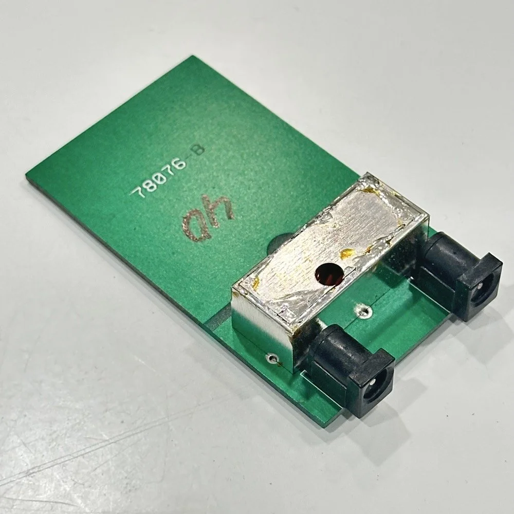
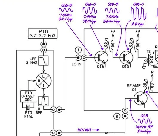
I started this journey by digging through the owners manual for the Scout as Ten Tec always shipped complete schematic diagrams with their radios. Sometimes there would be missing insignificant data, but you could trouble shoot the radio just fine with them. Once the radio diagrams were located, I started looking at how the band modules made it change bands.This turned out to really be quite simple but I was missing one or two critical values. You see the Ten Tec Scout 555 band modules have a crystal in them and the frequency on the crystal didn’t make sense…at first.
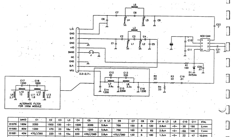
Above is the schematic and a photo of the board that goes with it showing the crystal that I couldn’t understand. This is what tells the radio what band it is on. Looks pretty straight forward at a glance, doesn’t it? Well look at that XTAL value at the end of the chart for 80 meters. Yeah, it takes a 7.444 mhz XTAL to get to the 80 meter band. So I figure the PTO is something like 3.0 mhz so it can get the first negative harmonic when mixed or something like that…nope…turns out I was totally wrong…
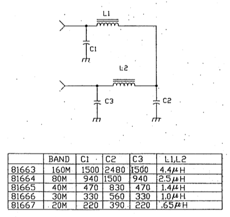
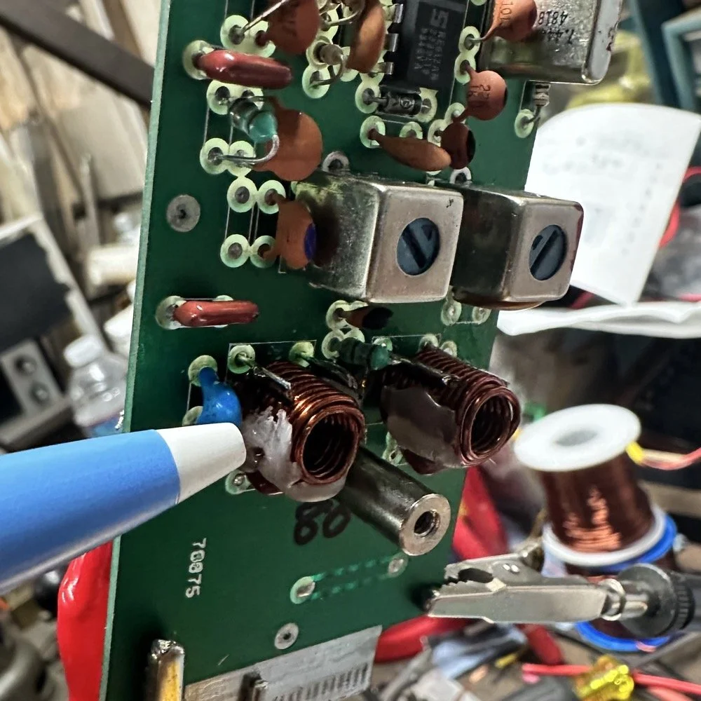
This is the other half of the band module. A classic low pass LC filter and that’s all. This is the output filter that the 50 power amp sends the RF to before it goes to the antenna. Below is what this part of the module looks like. These inductors and capacitors are shielded as they are delivering and filtering considerable power and could interfere with the small voltage levels on the other board that sits right beside it if they were not in the “can” or otherwise known as a ground shield. I don’t know why there is a hole in the shielding either as there is no adjustable parts inside the “can”. I chose this particular 80 meter band module for another reason as well. I have been inside this filter circuit before. When I acquired this module, the fellow I got it from told me it was dead and gave it to me. Turned out to be a broken lead on one of the inductors in this can. It took me a while to desolder this monstrosity to be able to access the parts inside of it. But persistence paid off as I was able to get it repaired and back in operation. I took a lead cut from a transistor and soldered it to the wire on the inductor and simply re-soldered it to the board and it came right back to life. So if you have a module that just stops transmitting all together, I recommend you pull the lid here and look at the inductors to see if one is broken free from the board, that might be all that is wrong with it. I also hot glued the toroids in place to help prevent this from happening again. Anyway, back to the project at hand…
I also looked inside several band modules to see what the differences were and I found some interesting things when I did. For starters, the 10 and 12 meter band modules both use the same circuit boards. They just leave out the second crystal and the switch parts for the second crystal and put a crystal in it for the 12 meter band only when configured for 12 meters. I guess, to be fair, I should have also figured out how the PTO worked as well then I could have figured out the reason for the odd crystal values, but here we are…
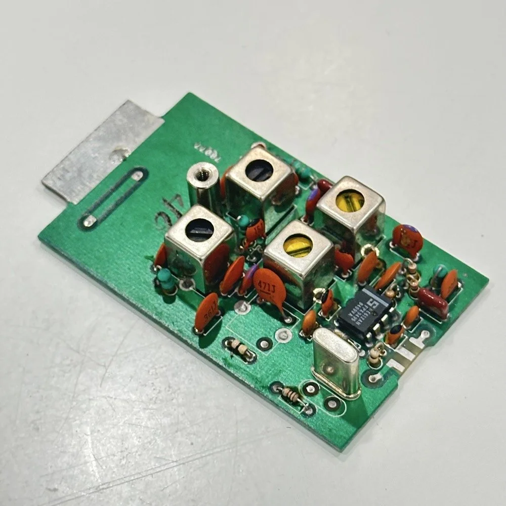
Another thing I found was that the engineers at Ten Tec used whatever circuit board blanks that they had on hand to build the band modules apparently. I say this because I found 10m circuit boards (the ones meant for two crystals and the switch) fleshed out with parts to make them into 40 m band modules. (Like the one in the photo above) They apparently just used whichever ones they had on hand at the time. Needless to say, what I thought was going to be simple was starting to turn into a pretty major endeavor.
You see it was starting to look pretty daunting since I didn’t understand what the reason for the odd frequency crystal was and that there were 4 tuned filters in each band module. Also the crystal value just didn’t make sense on the surface. The values were all over the place. I was about to throw in the towel calling it just too complicated, even though the parts count in a band module is really low…till I found two things. One was I looked up what the “555 timer” on the board actually was (Here is a hint, it aint no timer) and the other was NA5N’s website.
Excerpt from NA5N’s website showing the level of detail these drawings contain.
NA5N’s Scout 555 page is a figurative gold mine of information with just plain cash money piled on top of it, (just to drive this point home take a look at the piece above I grabbed for reference). I can not thank him enough for this information as without it I would not have been able to get this project working as quickly as I did. He also has some really interesting mods he has done to his own radio as well. If you want to perform his mods on your Scout, he gives you detailed information on what is done and literally how to do it…step by step almost. The greatest part of his page though is his info graphics he has built and placed there. These graphics show all sorts of information that the radio schematics leave out.
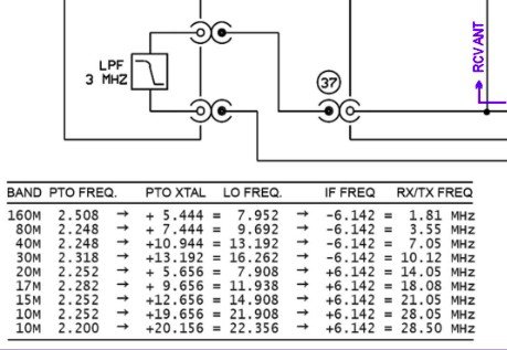
This and MUCH more is available on the NA5N website.
Things like the frequency path (pictured above) through the radio in a chart so you can understand how the engineers at Ten Tec arrived at each band frequency with these plug in modules and a PTO. Complete with oscilloscope test point and what you should be seeing at these points! Like I said, a gold mine buried in cash money…
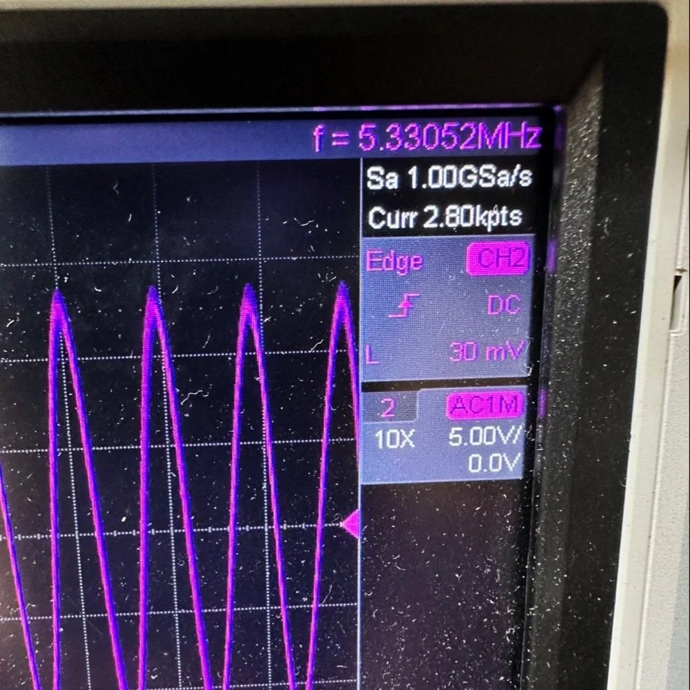
Based on his chart I went through the band module and looked at the filters for the various circuits and decided (more like assumed based on the values of the parts) that I could simply re-tune an 80 meter module and “push” it up to 5.3305 mhz easily enough and without too much fuss…nothing could have been further from the truth.
So I start tinkering with the filters and piping them through the nanoVNA into the s21 input so I can see the filter shape and all is well from what I can see. Turns out the low pass 80 meter band module filter cut off frequency was about 5.5 mhz or so to start the rolloff so the 60 meter band was still in the pass band! One down three to go! Next I figured out that the PTO is the same for every module since it is part of the radio and not in any of the modules so that filter also didn’t need any mods. This left two filters to re-tune, just so happens it is the two with the adjustable inductors in them. So I start with the LO BPF (Local Oscillator Band Pass Filter) that filters the signal passing through the radio from the antenna. Why they call it the same thing as the LO BPF that is in the output of the mixer chip is beyond me, but here we are… This didn’t go well as I was not able to get enough adjustment out of the inductor slugs to get the passband up to 5.350 mhz, shoot I couldn’t get it to tune up past 4.5mhz if memory serves me. It was far enough that I couldn’t get it work so I looked at what I had and decided to wind some air-core inductors to a lower value and see what I could do like that.
Well, to be honest, I don’t know how I was so successful here. Maybe it was the sheer audacity in the fact that I was woefully unskilled in building filters for HF or the mind boggling lack of knowledge of how filters work and how to make them, but I got it almost perfect on the first try! I made a couple different inductors by winding magnet wire on a 1/4-28 bolt (that’s a little over a 6mm bolt for the rest of the world) and the threads made getting good tight coil layers easy. I borrowed my friend’s LCR meter and measured them and blissfully declared them good to go at 2.0uH each. Did I mention this is a budget LCR meter and I have no way of knowing what the level of calibration is for this part of the meter? I also learned later that I can measure my inductors with a signal generator and a oscilloscope. Guess who now owns a signal generator as well as an oscilloscope...
Once wound and “measured” in the board they went! I then tinkered with the capacitors till the pass-band looked close to what I thought it should look like. (I had also learned from the wonderful world of youtube that I should see less than 1dB of loss in the pass-band and the 3dB cutoff point is where the filter technically is measured..typically.) As I mention in a bit, I used the wrong kind of capacitors (the little blue ones) to start with, although the module did work like this, I updated it with NPO capacitors ultimately as well.
I went down a long path of learning on this project, if you haven’t already noticed from the inserted comments in the story. I have very little formal training in Electrical Engineering, you see I went to a two year trade school back in the 1980s and basically got the “intro to electronics” that EE’s would get before learning things like matching the impedance of the filter to the next stage and to use temperature stabilized capacitors in RF filters so they don’t move the pass-band around when they get warm. NPO capacitors have become my best friends here…lol. A hint for my peeps who also didn’t study RF in college, look at the circuit board above that has the crystal on it. You will see the little capacitors on that board and some have little painted tops on them. This indicates NPO capacitors when the letter designation will not fit. I have now purchased a lifetime supply of these caps off of eBay…haha.
Anyway, now the pre-amp band-pass filter was functioning like it should. One to go…
Tune in for part two where we get into the problems I had to solve to get this module working and how well it works now that I have figured out my mistakes.