WK4DS Amateur Radio Blog
Search Posts
![Ten-Tec Scout 555 60m Band Module: IF Filter Redesign & Final Testing [Part 4]](https://images.squarespace-cdn.com/content/v1/5d17806ce65eba00011667cb/083bf6b4-e926-4837-8a07-9c333538b44c/IMG_1543.png)
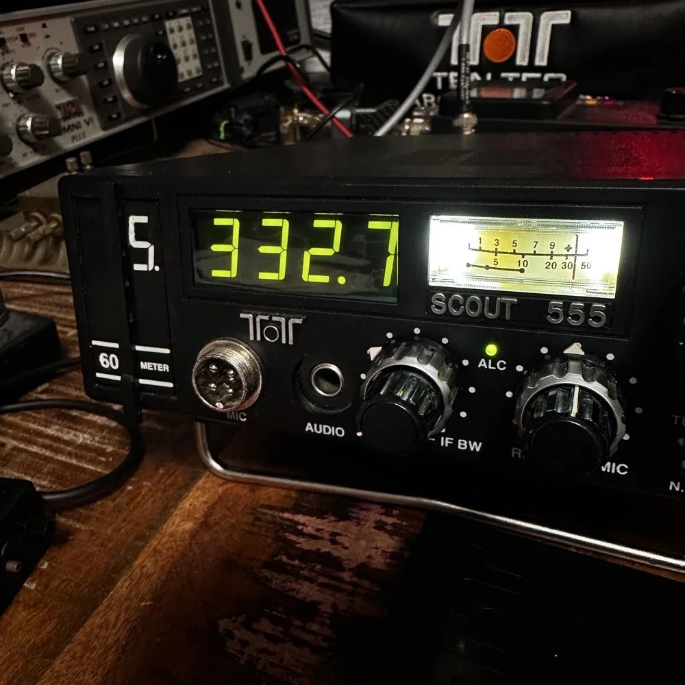
Ten-Tec Scout 555 60m Band Module: IF Filter Redesign & Final Testing [Part 4]
Today saw me finish the TenTec Scout 555 60 meter Band Module Project in the workshop, now it is on to phase 2, testing in the field… I had wanted to rework the filter in the IF stage as it was not great from before. I was able to get a signal out of the radio, but the filter shape left something to be desired…
This is the 4th episode in my Ten-Tec Scout 555 60-meter band module series:
- Part 1: Initial Conversion and Filter Design
- Part 2: Crystal Selection and Mixer Circuits
Today saw me finish the TenTec Scout 555 60 meter Band Module Project in the workshop, now it is on to phase 2, testing in the field… I had wanted to rework the filter in the IF stage as it was not great from before. I was able to get a signal out of the radio, but the filter shape left something to be desired…
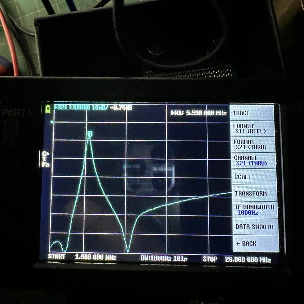
The first chart image is of my filter after I got the radio to work. This is not what a bandpass filter should look like. The lower photo is of a factory TenTec VERY narrow bandwidth 40 meter bandpass filter. Turns out, this is almost impossible to replicate with discrete components that are not adjustable…as you will see. They used two tunable inductors to achieve this filter shape. I almost went to the trouble of adding some trimmer capacitors to mine, but as you will soon see, I felt it wasn’t needed. I soon learned what a filter Q is and why it matters when your trying to build a filter. I used some online calculators to get the component sizes for the filters and after messing around with a couple, I found one of the calculators had came up with numbers that were actually able to be made in my shop.
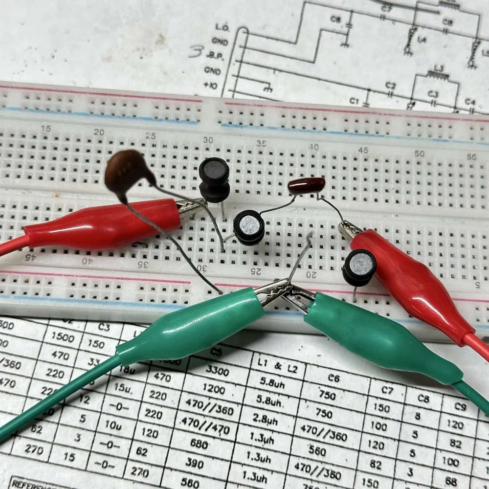
Armed with this information I decide to breadboard this filter first so I could tinker with it before soldering it to the band module circuit board. This, as it turns out, is a terrible idea if you plan to simply transfer the parts to the board and solder it all together. There is SO much stray capacitance and inductance at RF frequencies with a breadboard that you can build up a circuit, but when it comes to making the final item on perf board or Manhattan style, that you WILL use different values.
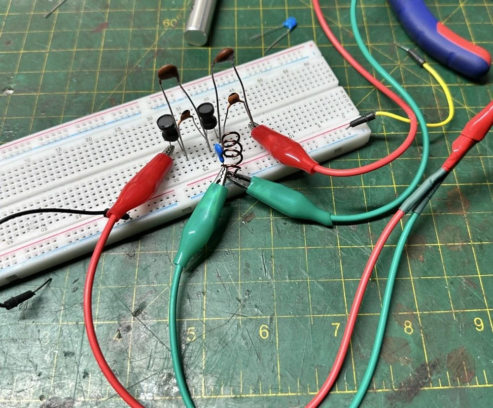
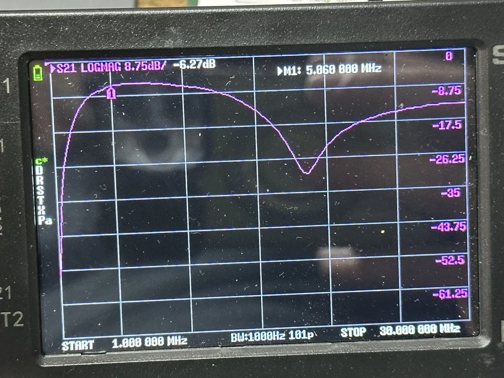
Looks good doesn’t it? Well look at the plot below! It actually looked great! It did have some insertion loss that I was not super happy about, but that plot looks great! Yes, the one inductor is hand made, I didn’t have one small enough in my little kits to work here I so wound one for the job. Notice how long the leads are on those components, that will come into play very soon…
I may have gotten a little aggressive with the passband width… I think it was set to 200khz or maybe 500khz, but it was not much. I think the values I put into the online calculator were 5.4mhz center frequency, 500khz bandwidth and 3 LC stages in a “T” configuration. The bottom line on the chart is -70dB which is unbelievable! This thing was incredible! So I get the 60 meter module out and take it apart and strip out the old filter I had previously built wholesale leaving a clean slate for the new filter…
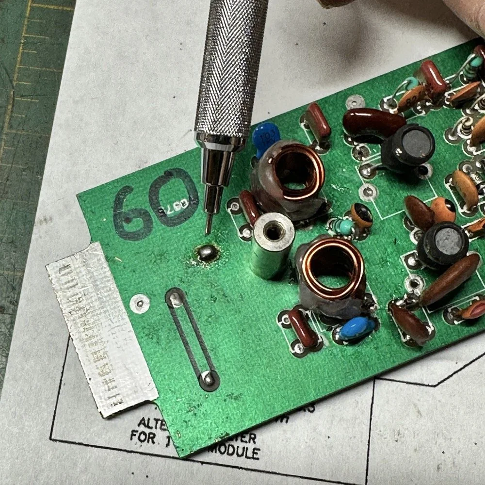
After I had the old filter gone and cleaned up a little, I cut me a pad as the new filter layout and the TenTec layout are different so I wanted to not have to permanently alter the circuit board other then removing the old components. This pad became the central connection point for the three stages. A little hot glue and I was in business! I simply tinned the whole top of the pad so I could land part leads where ever I wanted on it. This worked really well…much better than the filter I am about to build as it would turn out.
SIDE NOTE ABOUT MODIFYING SCOUT BAND MODULES:
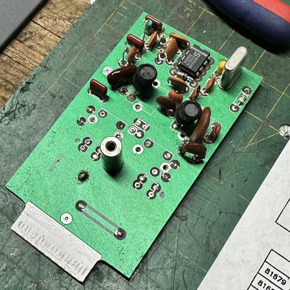
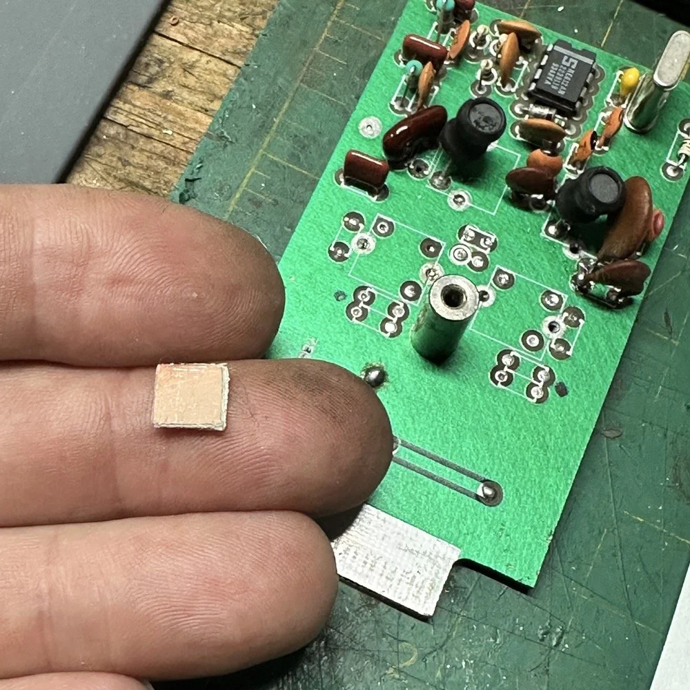
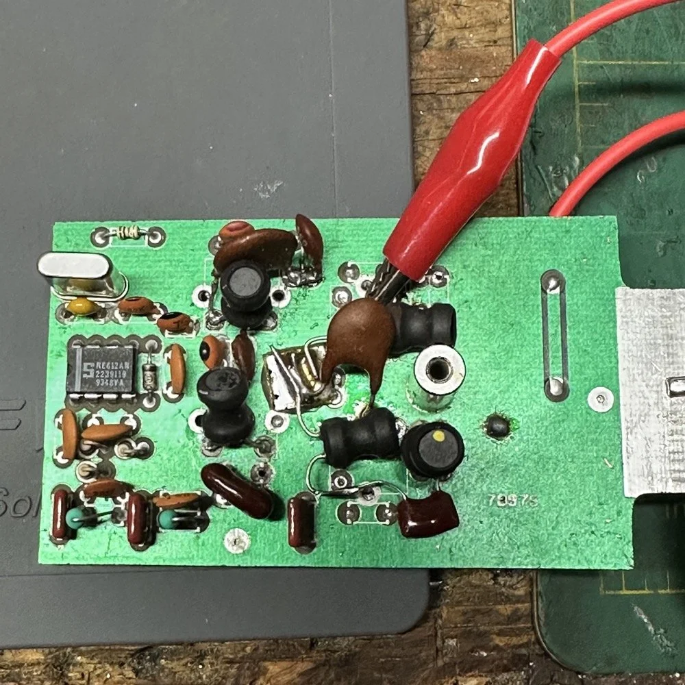
What I am pointing out in these two photos is a home made Via that I added. You see, when you remove the canned tunable inductors from the board, turns out you break the grounds. TenTec decided that since these things were going to be here anyway, might as well use them for something. So they apparently decided to make them connect one ground plane to another in a couple of places on the board. Once you remove the cans, you lose a critical ground path…or two. I took a finger drill and a very small drill bit and drilled a hole from one trace to the ground plane on the opposite side(I am confident these are only two layer boards), then I soldered a bonding jumper wire in the hole so both planes would once again be connected again and all the stuff would continue to work properly. You also get to see the old homebrew filter in the below photo as a bonus.
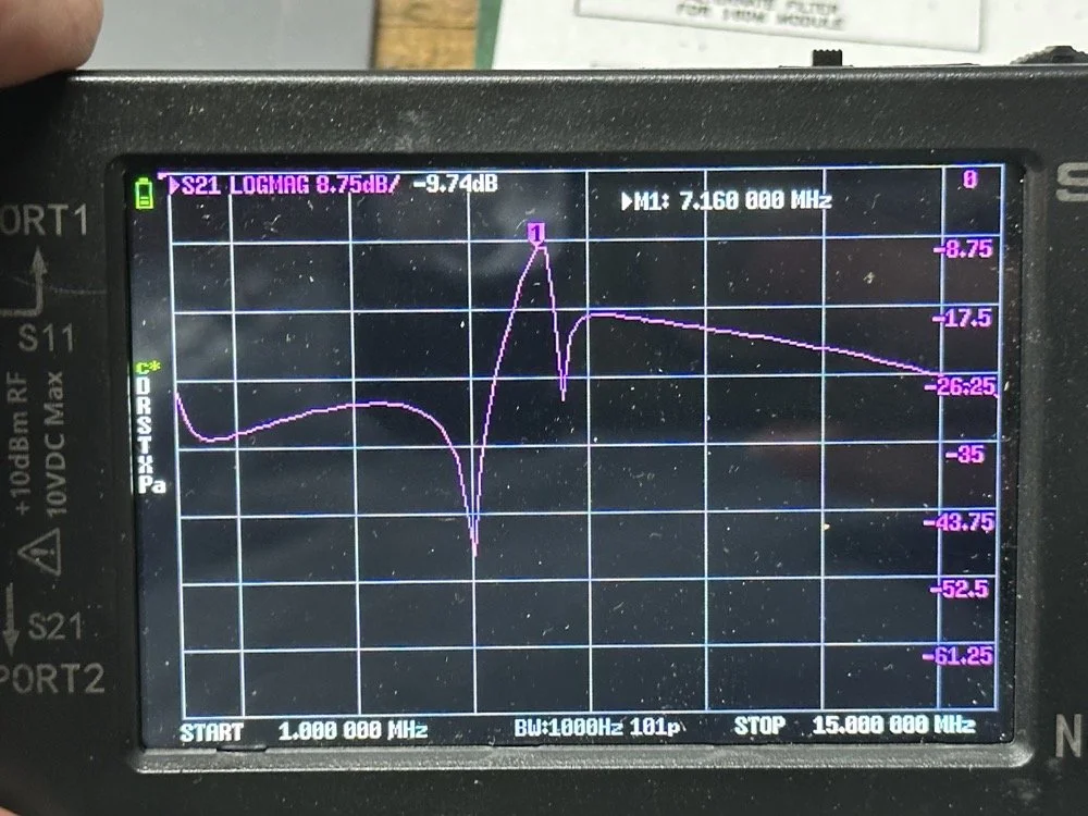
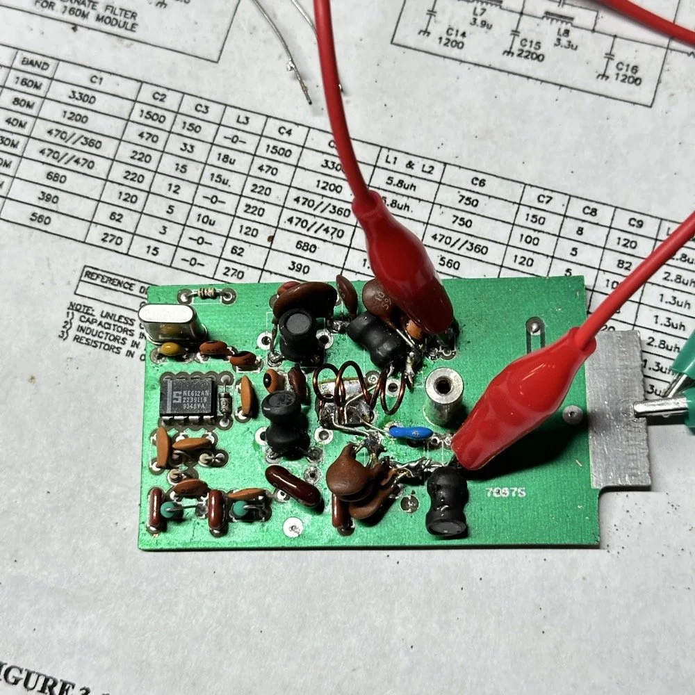
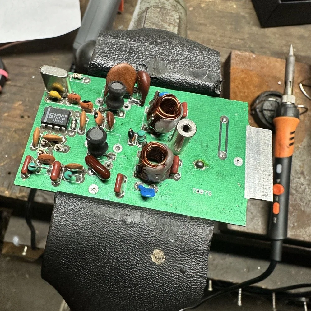
Below is the result of me simply attempting to move the parts over to the circuit board and soldering them in place… What a mess. I started with the exact parts you saw on the breadboard, but when I connected the nanoVNA to the filter I found the center frequency had moved up 500khz! It was now pushing my desired frequency out of the passband!!! I was seeing something like 16dB of loss at the desired frequency.
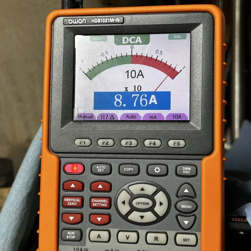
This is the world of ultra high Q passband filters made with inductors and capacitors I guess. Once I removed all the stray capacitance from the breadboarded system, all the capacitor values went down enough to make the filter not usable. That is why you see the mess below, I didn’t have room for the trimmer caps I have on hand so it was good ole trial and error method instead to get the passband in the right spot. To be fair, this mess actually worked, it just had something like 12 or 13dB of insertion loss in the filter which made the output power go way down. I used the amp meter to check it and the current draw on transmit with this filter was 1.8 amps and the current draw with the factory 40 meter band module was 9.3 amps. So I took a break and grabbed some food and went back to the drawing board…
I am going to admit something here that might make some people unhappy with me…I decided to use Claude AI to see what it would come up with for a filter design. I gave it all the parameters I had used earlier and (since it is a chatbot after all) had a conversation about what my goal was. I decided to move the bandwidth out to 1mhz giving me a decent shot at making a working filter without adjustable parts and using only what I had available on site.
This AI model came up with a “T” filter but instead of the center 2 LC components being in parallel, they were in series and so I built it. It tested really bad as far as rejection goes as it only attenuated about 8 or 10dB across the whole band and looked more like a poorly designed high pass filter instead. This did give me some inspiration though. So I went back to the online calculators that are there to figure part values for you and changed my approach. I went to this website and just made a low pass filter and then a high pass filter and coupled them together with an inductor. Why did I choose an inductor? Because all the capacitors I tried kept increasing the losses in the filter output is why. As it turns out, if you attenuate the IF signal in the radio the output power get lowered and the radio goes “deaf”…
Below is what I came away with finally. Yes, only 3 inductors and two capacitors.
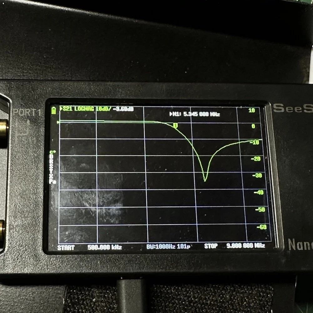
Below is the filter shape for this simple filter design too. It is a lot better than what I started with and I was able to build it with parts that I had available to me at the time. Could the passband be narrower? Yeah, it could, but I am not going to throw too much shade at this filter. This is what ham radio is all about in my book, experimentation. The marker is at 5.64mhz which is 250khz above the highest place I can transmit so I know this filter wont attenuate my signal and the radio will work as it should.
The original values for the filter ended up being wrong, but I simply did what I did in the previous filter build and just used it as a jumping off point and started switching out parts one at a time with different values. This tactic coupled with looking at the nanoVNA to see what the new part did to the filter shape gave me the results you see. At first I didn’t write down what I had done, but it quickly became apparent I needed to note what I had done and so things progressed much more quickly once I did.
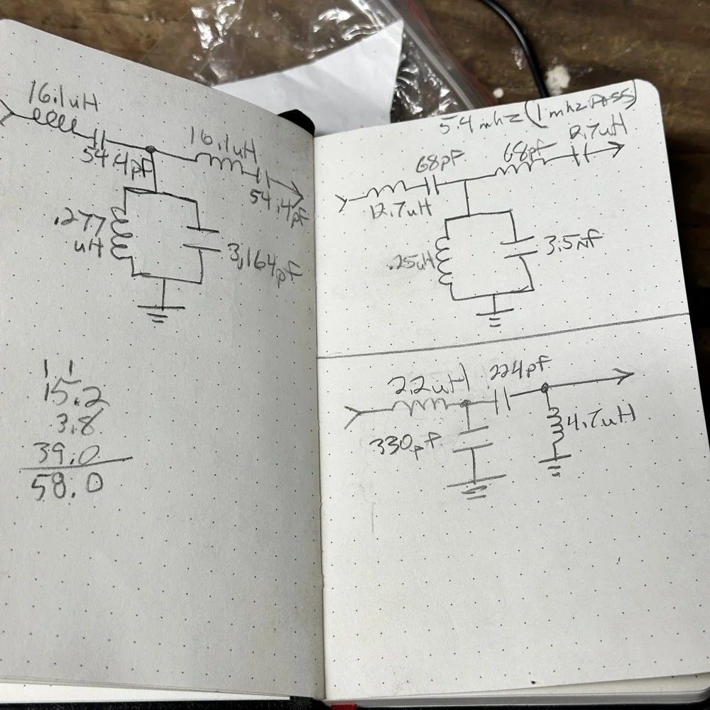
The above photo ( bottom of the second page ) is what I started with on this part and the lower photo is what I ultimately ended up with for the actual parts I used to build the filter. You can see where I was trying all sorts of stuff to get a working filter, these are not the only sketches either…
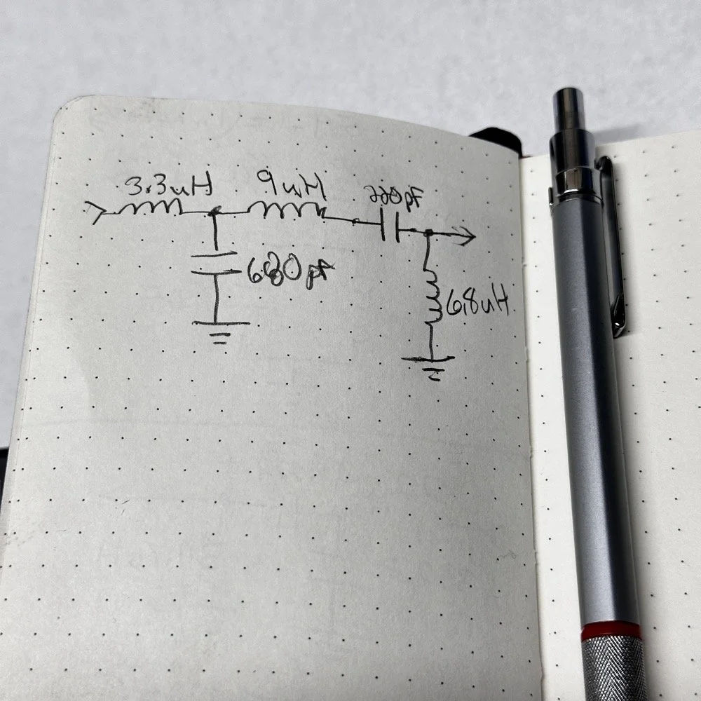
This is what I ended up with ultimately to get the filter shape above. The impedances are wrong, I am sure as I didn’t take them into consideration at all, but the radio is working correctly now (from what I can tell) and transmits almost at full power. Shoot, they could be right and I just got them right by accident, I really don’t know to be honest.
This is the output power draw now for the 60 meter module on the same radio as the 40 meter module previously compared. I can live with that! I checked it when I got into the shack at the house and it is a little over 35 watts into a 1.3:1 SWR load. That will work just fine for me. (Note: The current reading was into a 50 ohm dummy load at the workbench so I don’t know the exact current draw in the shack.) This radio will produce more output power too, I have it dialed back on purpose to about 40 watts for the 20 meter band module that I use with this radio.
This is what the final filter looked like when I was finished building it. This looks a lot better than that mess I started out with above. Not overly complicated and generates a respectable filter shape. The radio sounds good too. So I am happy with this.
Side note about the above photo, I had noticed in my original filter design that the orientation of the inductors made a difference in the filter profile on the nanoVNA so I started marking them with a paint pen to remember the orientation. This filter didn’t seem to care too much about that for some reason but the original cared ALOT.
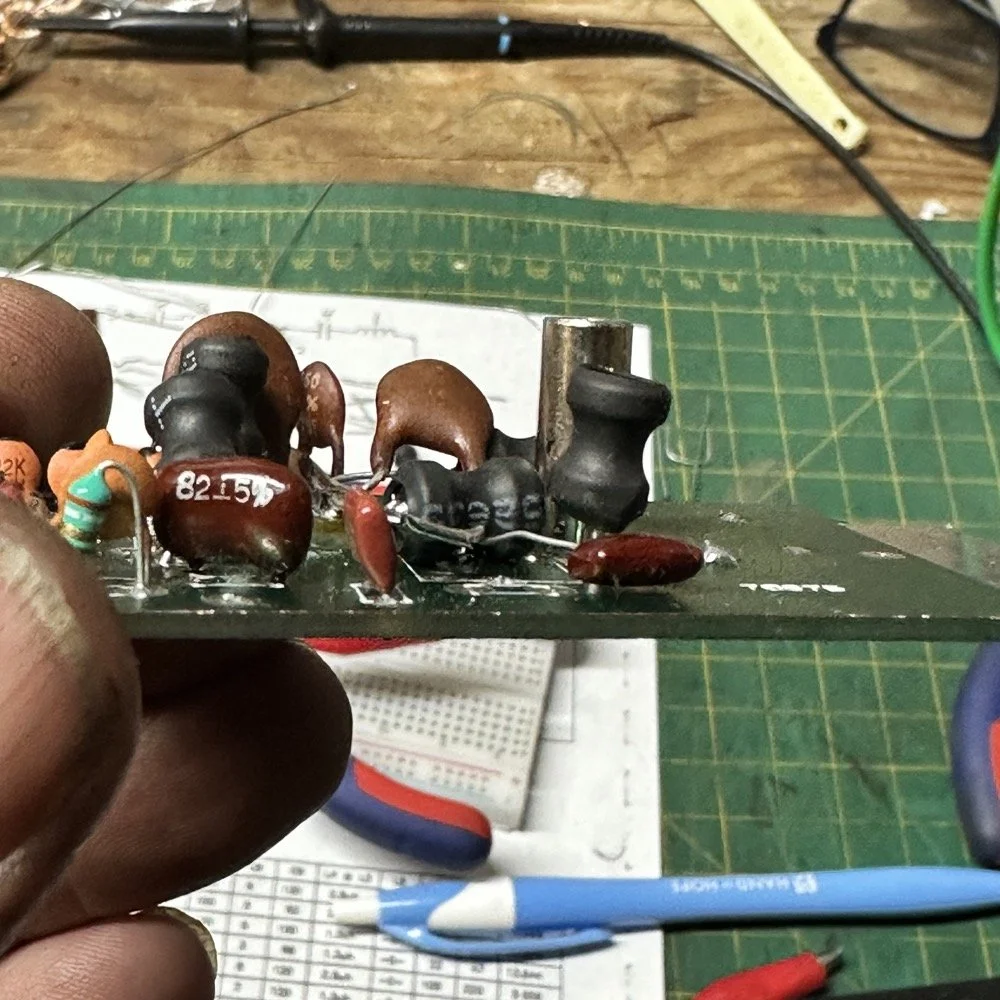
The side view photo shows something else the I have not mentioned in these write-ups. The filter has space constraints. The filter can not be taller than that metal post or the other circuit board with hit the parts and the parts can not go past the post either as that is the space for the output low pass filter from the other board. So parts count matters…
It feels oddly satisfying to see the finished module and to use it in the shack. All I did last night was listen to some stations having a QSO and how well it could hear them. I also dialed up the webSDR again and listened to myself calling CQ for a bit with no takers on a different channel. I know the radio is working as the listening station in Utah could hear me…
Tonight I hope to find a chance to jump into a QSO with someone and see how it sounds to them.
I hope this has inspired you to do something with your gear whether it be build a kit or modify a device to do something new or different or even to repair something you have that is not working now…shoot maybe you will learn something you didn’t know before! That is what has happened to me on this journey, I have learned a lot about how filters work and what affects them in use. I am starting to understand impedance matching the stages as well as insertion loss. A lot of things I never understood before are now becoming more clear. I also have a much clearer understanding about how the TenTec Scout 555 radio works as well…
Thanks for following along on this 4-part journey! If you build your own 60-meter module for the Scout 555, I'd love to hear about it. 73!
You can help support this website by using these Amazon Affiliate Links:
QRP/Portable Radios:
Antennas & Tuning:
CW Equipment:
Power & Accessories:
Organization & Transport:
BONUS ITEMS
WK4DS - David
![Ten-Tec Scout 555 60m Band Module Build: Final Filter Tuning & Field Testing [Part 3]](https://images.squarespace-cdn.com/content/v1/5d17806ce65eba00011667cb/c2e621e7-9bb7-4b40-b20f-7c5c2dc8be7d/IMG_1257.JPEG)
Ten-Tec Scout 555 60m Band Module Build: Final Filter Tuning & Field Testing [Part 3]
Today I took the newly minted 60 meter band module for the Ten Tec Scout 555 out on it’s maiden voyage to a POTA activation. I made a contact in the shack with it before leaving on my short trip to Florida so I felt confident it was ready to use. Today we are discussing what happened and what is going on from there with the 60 meter band module project. (Spoiler Alert: It kinda wasn’t really ready yet…)
Today I took the newly minted 60 meter band module for the Ten Tec Scout 555 out on it’s maiden voyage to a POTA activation. I made a contact in the shack with it before leaving on my short trip to Florida so I felt confident it was ready to use. Today we are discussing what happened and what is going on from there with the 60 meter band module project. (Spoiler Alert: It kinda wasn’t really ready yet…)
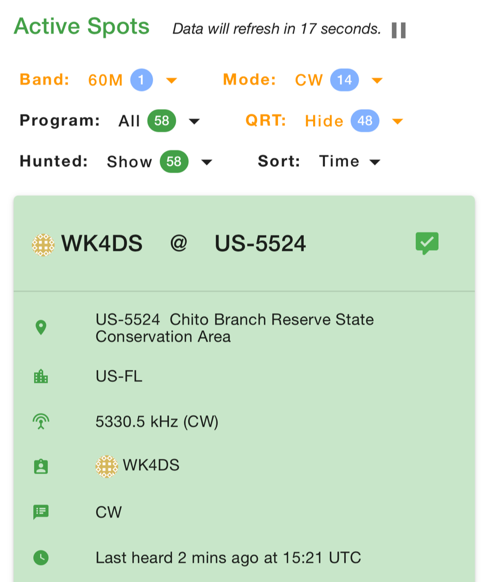
As you can see from the spot page report below, I was the only one on 60 meters this morning and it was roughly 9:45 (might have been 10 to be honest, I cant remember) local time before I got everything setup and running. This made 60 meters not a great choice to be honest for a daytime band. The 60 meter band is a great evening and really early morning band, but once the sun comes up these low bands tend to get really noisy. The band noise was quite low to my surprise today. I usually get a good bit of man made noise in this spot so I was pleasantly surprised when the noise floor was really low…or the band was closed. Who knows at this point?… I am starting to lean towards the band being closed as I couldn’t hear the FT8 crowd either, and those guys are ALWAYS on the band if it is open at all.
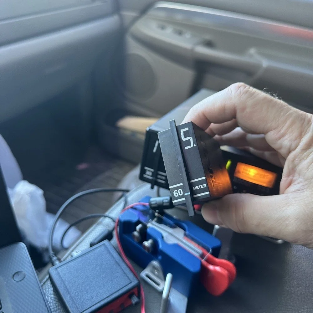
Undaunted by this and the lack of any kind of signal on the band, I setup and started calling CQ…and called …and called… then I finally got a station in North Carolina ( WA4CHJ - thanks for answering me, I really appreciate it. ) and with that I had a call in the log on 60 meters with a Ten Tec Scout 555!!! I can’t be certain this has been done by someone else, but as far as I know, I am the first to make that happen! After calling CQ for about 7 more minutes with no answers, I noticed that the ALC light was not coming on when I would key the radio and it was showing about 20 watts forward power on the built in meter. I checked the SWR and it was fine so it had to be in the module. I tried calling for a little longer and started getting an odd kind of “hashy” crackle on the CW sidetone and when it would make this sound the power would go up to the normal level and the ALC would come on…Upon this realization, I decided it would be better to sideline the module till I got back to the work bench next week instead of risk damage to the module or the rest of the radio. It also occurred to me that the RBN never heard me, not one time, while calling on this day so the band must have been closed…
You gotta admit though, that setup below is kinda sweet… Also the frequency is tuned off by the side tone (this is normal for the Scout 555) so it is actually on 5.3305 mhz in this photo. (I checked it with my Omni-VII before leaving home so I knew it was on frequency)
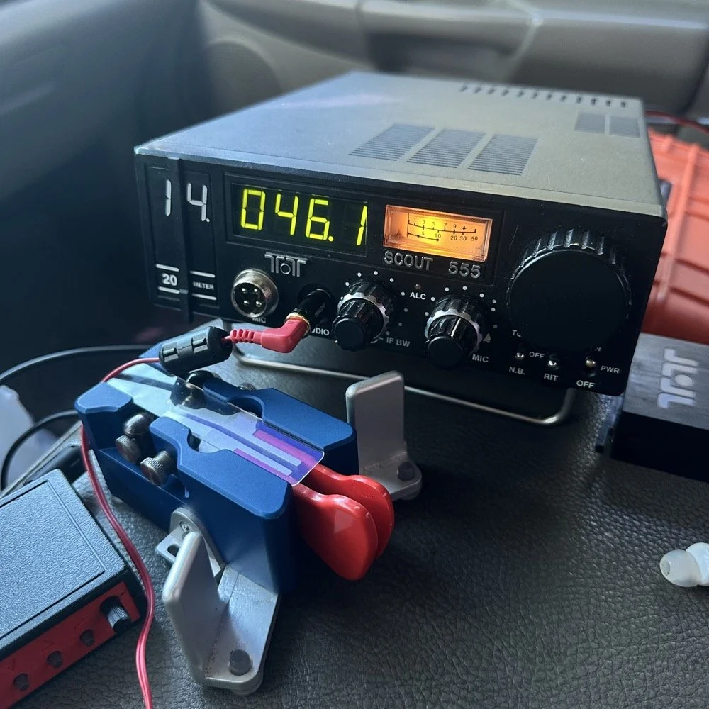
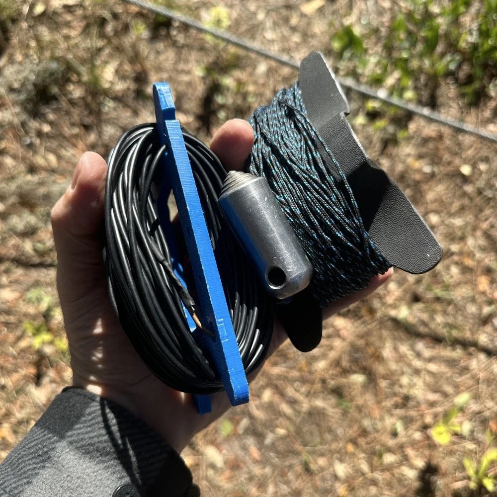
I setup a long wire today since my vertical will only tune to 40 meters with the home-brew load coil and I was a little strapped for time and just used an MFJ manual tuner instead. This allowed me to get a 65’ wire up in the air and a couple of radials and run with it. I was able to tune it well into the 60 meter band with the null covering the entirety of the band space so no tuner changes were needed as I moved around in the band.
SIDE QUEST:
This little segment will be about the rest of the activation for my readers that follow those as well.
Today was a great day…once I moved to 20 meters! Turns out 20 meters was alive and well today with only about 6 CW activators on the band. This gave me plenty of room to find a nice quiet frequency as well as lots of hunters were out today as well. I tuned up on 14.047 mhz and started calling CQ, I think it took two calls max to call in a extraordinary pile up for me! The stations were deep and strong! I swept aside my normal pleasantries for the most part and compacted the closing to what I felt was a minimum and the calls just kept coming in! I worked 49 calls in 41 minutes! That is a record for me! At this point I literally called CQ one last time to make sure there was no one else waiting and got no replies so I immediately called QRT and shut down the radio. I was actually out of time and had to get the rig packed up since I needed to pick up the wife from class. This had to be the fastest 49 calls in the history of WK4DS amateur radio in my totality of radio… haha.
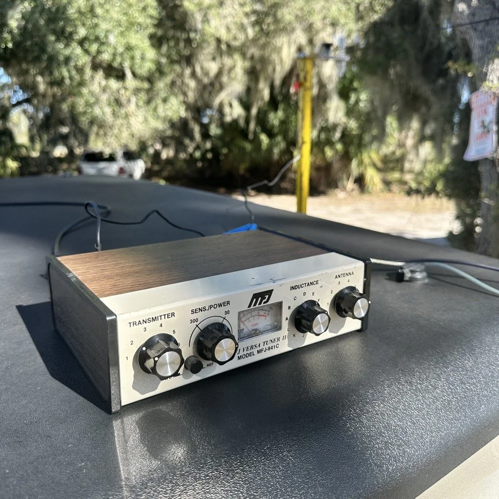
MFJ was a company that some complained about (Surely you have heard them called More Fine Junk) but to be honest, everything I have ever bought that they made has worked exactly as described and was pretty reasonable in price too. I hope someone fills these shoes for the future hams coming into the hobby, this little tuner is amazing for what is in that tiny little housing. It tuned this long wire just fine and didn’t need huge capacitors or inductors to do it. Not to mention it was really economical too. Good kit is hard to find so if you plan to do POTA in the field, I recommend one of these in the box of stuff, it WILL bail you out one day. This tuner has bailed me out a couple of times now…
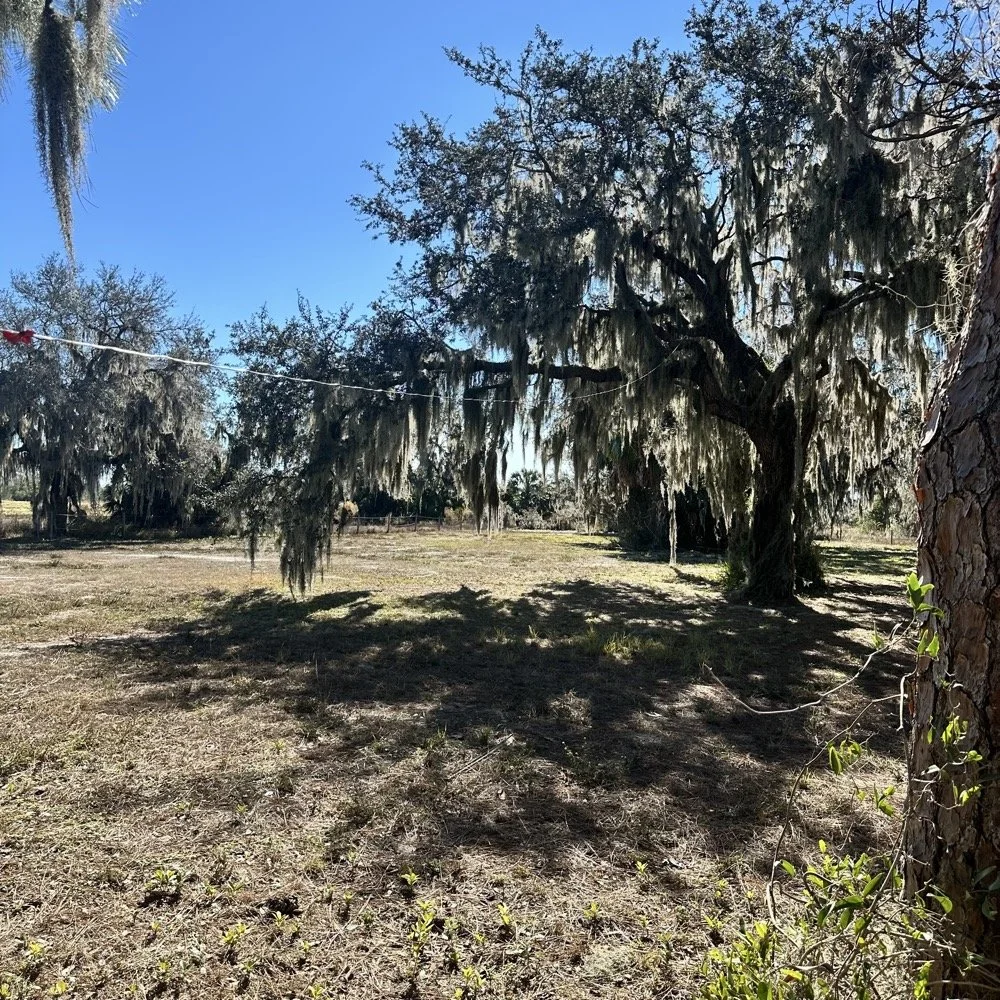
A throw line, a weight (that I made in the machine shop out of scrap stainless steel) and 65’ of wire made for a lot of fun today.
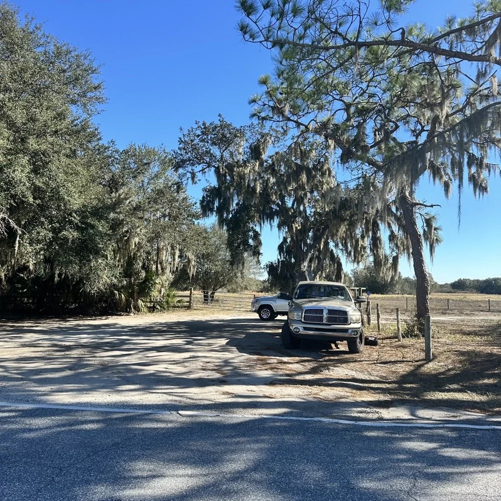
You can’t really tell it in the photos, but I did use my vertical antenna truck mount. I used it as the truck side anchor for the long wire and strung it up into the tree you saw earlier. This turned out to be really convenient I must say.
SIDE QUEST ENDED:
Back to the project at hand…
A week later and back in the shop at home with the band module on the work bench again and a Scout 555 in the shop now instead of the ARGO 556 to give me full power (40 watts) into the module (I pull the output power back to 40 watts to help protect the radio).
Now I can sort out the last of the details with the filters under full load. I am starting to think that the LO BP filter still needs some work as well as the signal level on the mixer output filter is REALLY high. I don’t remember the exact number but think of something like 700 or 800mV level instead of the 50mV that is supposed to be coming out. I tackle this problem first by building up the board like I had before so I could see the level coming out of the mixer filter. I had removed one of the impedance matching capacitors completely (750pf) without understanding what I had done and this was a big part of the problem with the level being so high. I did some simple math and came up with about 600pF instead of the 750pF that was supposed to be in the board since it was now tuned for 5.35 mhz instead of 3.55 mhz. I ended up using a 560pF cap and the level looked like the photo below on the base of Q16 in the radio. Remember this data is at this link if you need it as NA5N made these wonderful signal flow graphics.
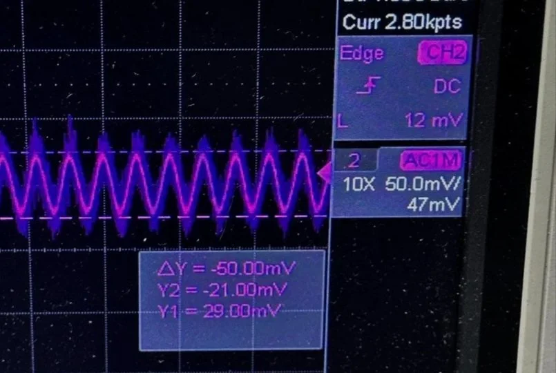
Right on the money at 50mv! I will take that everyday! All the noise you see on the signal is generated in the radio as far as I could tell, all the band modules I tried today looked like this on the base of Q16…or I was picking up the noise from somewhere else, I really am not sure to be honest with you. The output from the collector looked fine though so I don’t know what is happening here. I know this is good now as the frequency in the radio is stable and doesn’t drift. Those NPO capacitors paid off! (NPO means “Negative-Positive 0 ppm/°C” or more plainly, these capacitors are stabilized so they don’t drift in value with a change in temperature) My circuit doesn’t look exactly like the original Ten Tec filter but it does work.
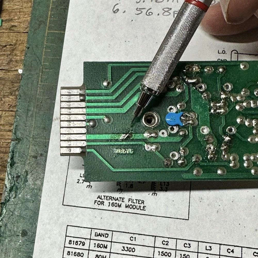
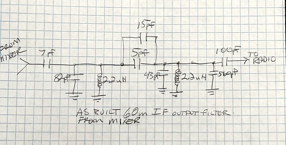
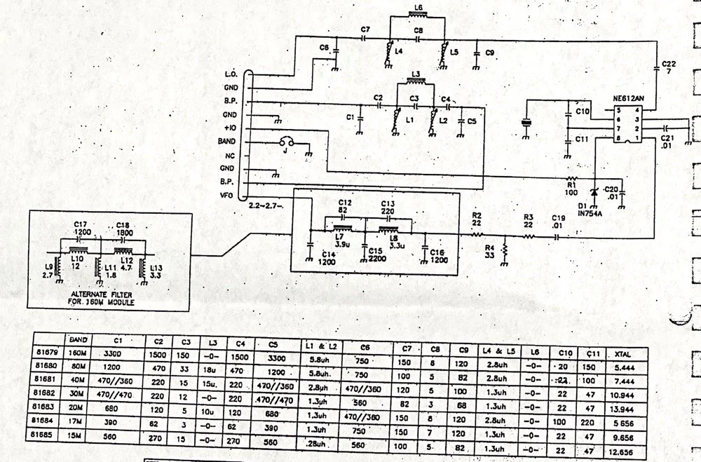
Below is what I ended up with for the filter circuit. I added the one capacitor that was not in the original design (the 43pf cap) and this did seem to help with the shape of the filter so I left it. I drew my filter flow direction backwards from the Ten Tec drawing but you can see the differences from the 80m filter I started with below. Also a couple points of interest here. In my 60m module (formerly an 80 meter band module), the output from the mixer chip is pin 5 on my board and not pin 4 that feeds into the filter network. If you look at the spec sheet, this is fine as both pins are output pins, but it was a curious mistake in the schematic I found while troubleshooting my module. Another curiosity to me is that the schematic shows L6 in parallel with C8 (5pf) in the center of the filter. Not one single band module uses L6… at all. The chart underneath the schematic shows a -0- symbol on each one of the modules for L6, to confirm this, I looked in three different modules and none of them have this inductor in them. It isn’t present on the 10 or 12 meter modules either as they have a different layout for their filters. This was a provision that later was deleted I suppose. Kinda neat to find things like this while doing a project. Makes you wonder why they provisioned for the inductor but never used it. The board has two through holes for the inductor as this is where I placed my 15pf cap (which made adding it really convenient.) So it was obviously designed into the system to start with… Maybe someone who was an engineer at Ten Tec back then will comment.
Excerpt from original Scout 555 owner’s manual.
With that out of the way I moved on to the output LP (Low Pass) filter that the 50 watt power amp flows through to get to the antenna.
The above photo is of a LP filter out of an unmodified 80 meter band module I used for comparison. If you will notice the roll-off is right smack dab in the middle of the 60 meter band on this particular module.
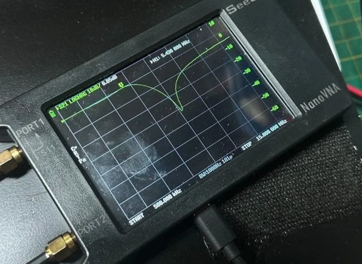
The photo below is of the 60 meter band module sweep that I am building out of an old 80 meter band module. If you will notice I have the nanoVNA set to 5.430 mhz on the marker, and it is hard to see, but the signal is at 0.05dB which is basically zero losses at the highest band position possible. This would imply that the filter would allow the 60 meter band through just fine, but it would not…
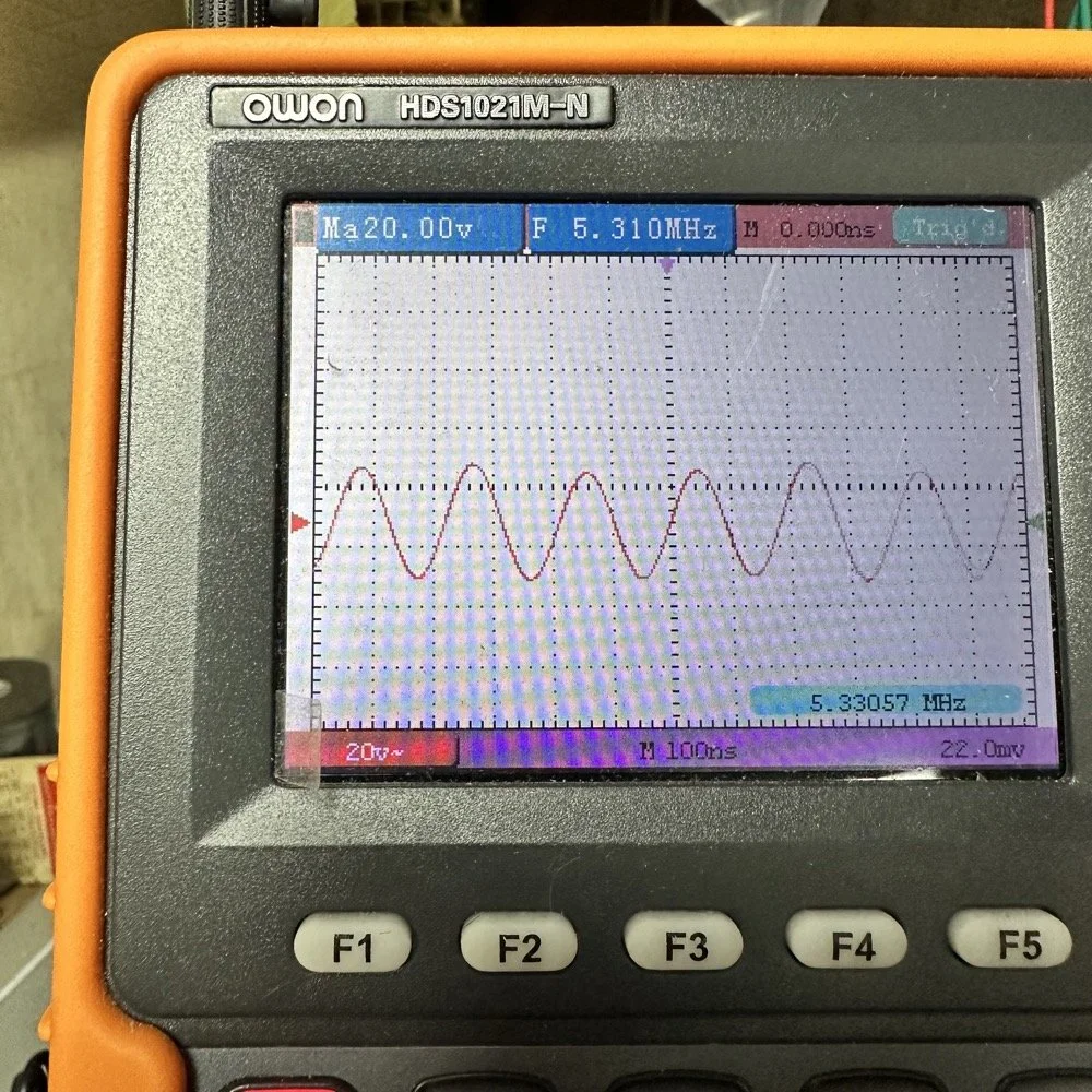
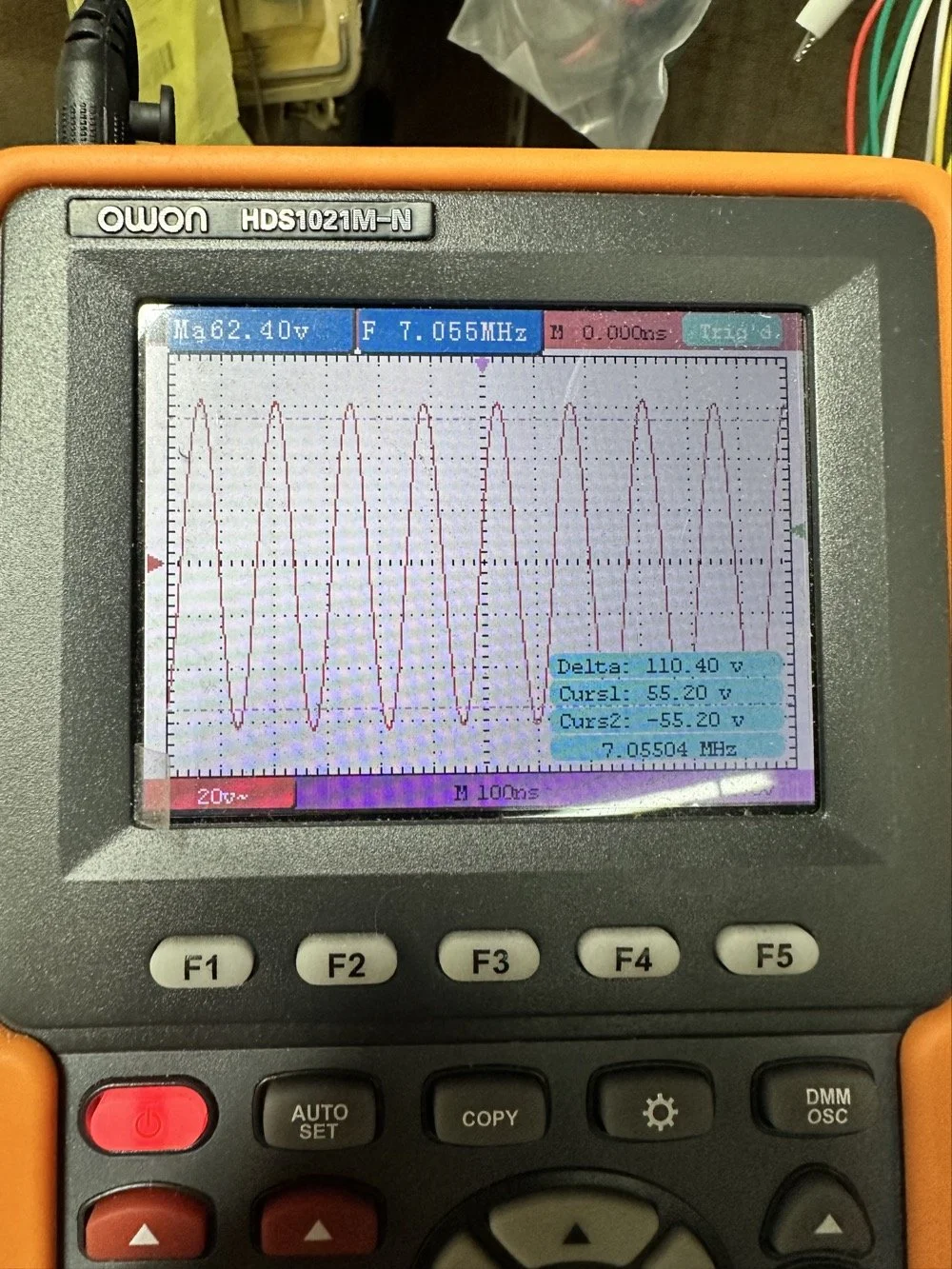
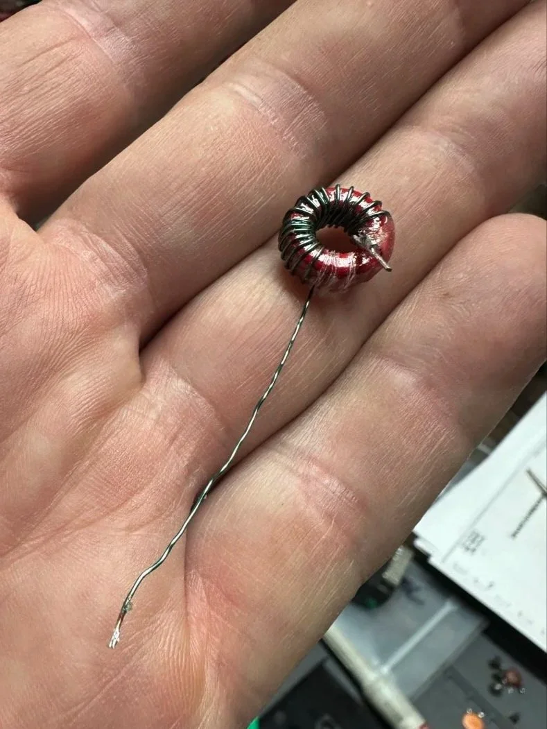
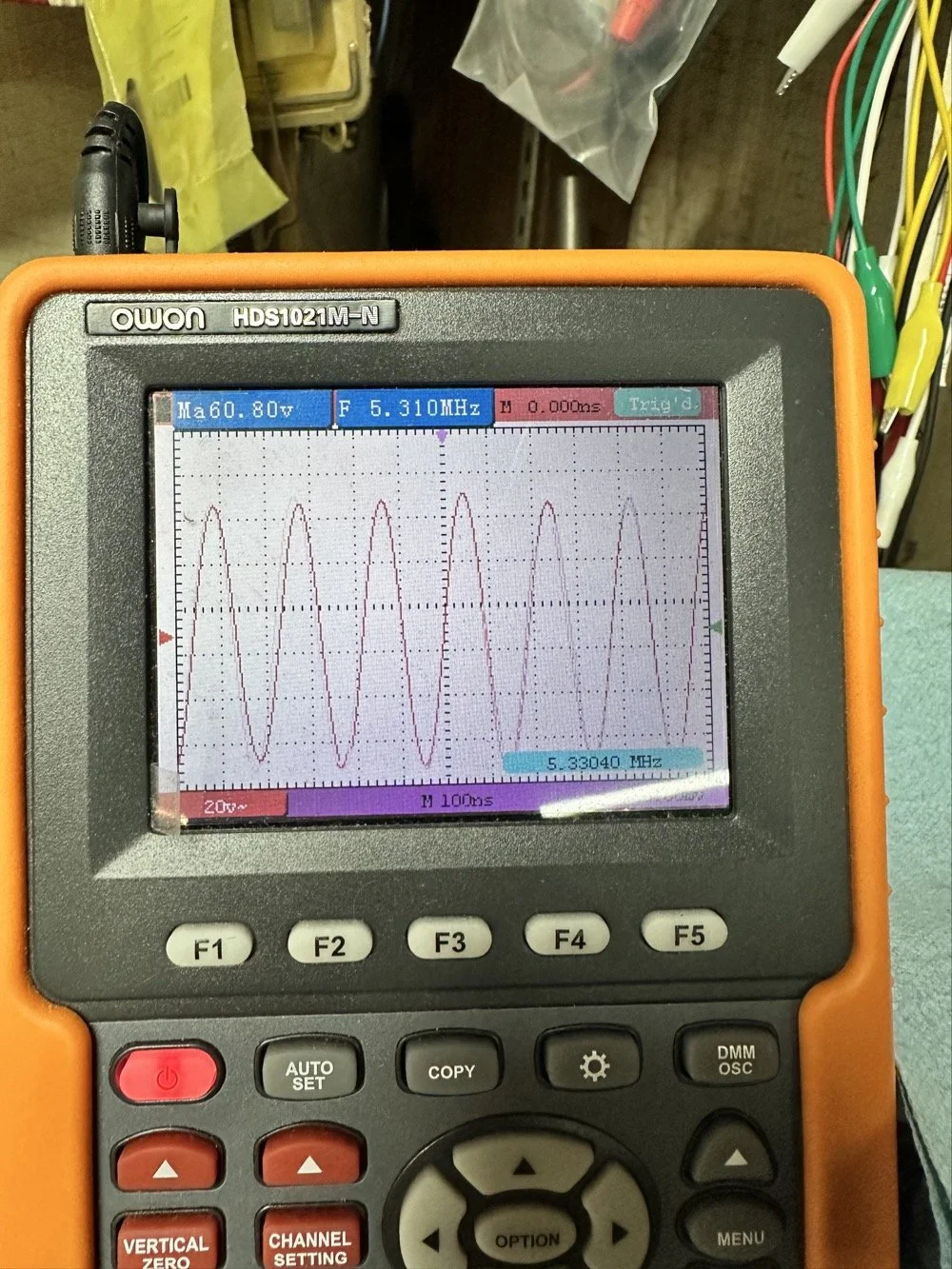
This is what the radio was sending to the dummy load after it passed through the LP filter module (above photo)… So to test this theory, I installed a different module (40 meters) and got what you see below… That is a little over 120 volts peak to peak on 40 meters. Yeah, you don’t change the output power of a Scout without a screw driver so the fact that the 60 meter band module I made is only letting a little over 30 volts peak to peak through it AND knowing that the 40 meter band module is passing over 120 volts peak to peak, tells me the 60 meter filter is choking off the energy and it is probably heating up the toroid inductors pretty good at the same time. I suspect that is what I was hearing the other day at the park when it was crackling after a while. I just hoped that I had not burned the wire on the inductors with this energy… If so I would have to rewind the inductors completely from scratch. Fortunately, I do have a roll of magnet wire I could do it with…
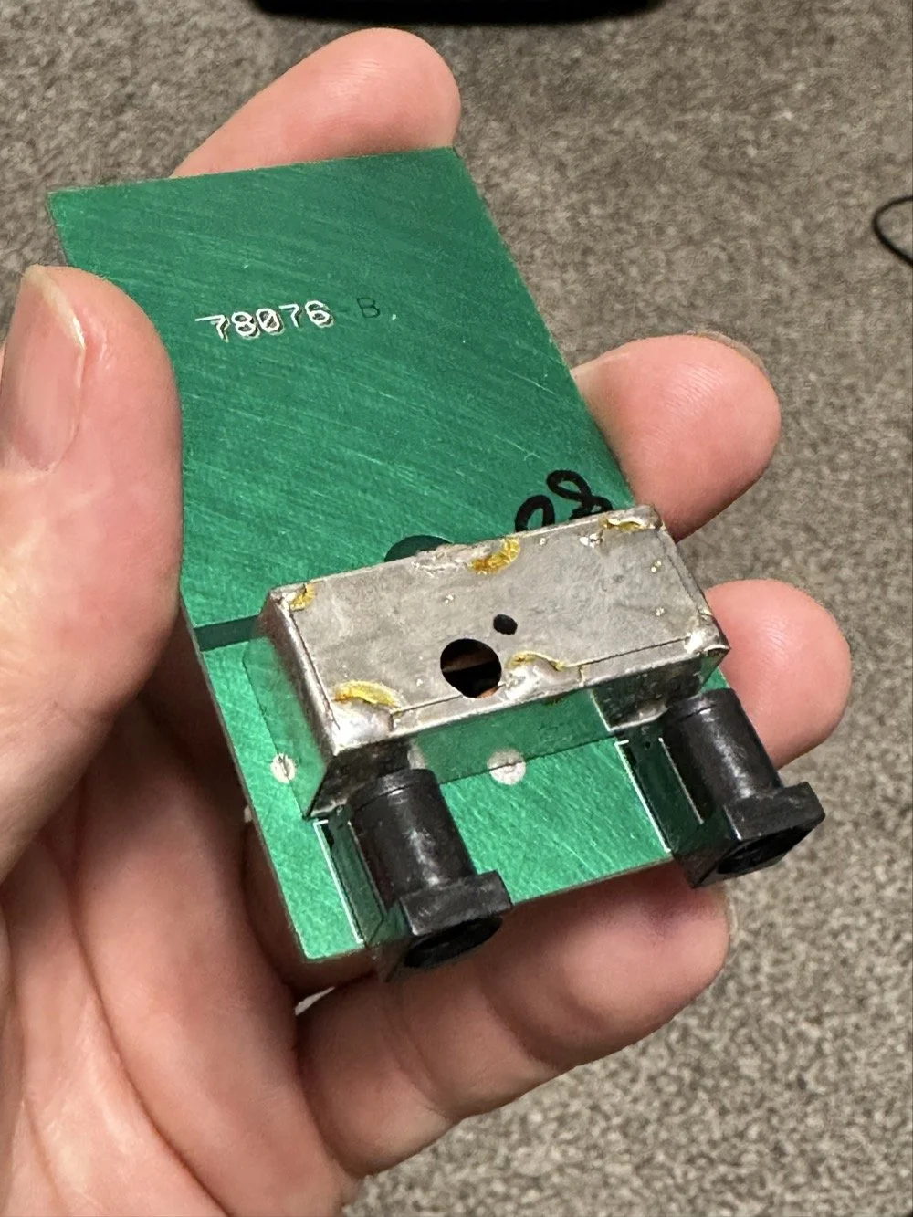
Into the final output LP filter I went (the one in the can) to see what I could do with it. The first photo shows the “can” the filter is shielded inside of to keep stray RF at bay.
The second photo shows what is inside of this can. This is also a photo of my completed filter with modifications to make it work on 60 meters. I found that this module had been tampered with once inside. Now to be fair, I did work on this module at one point to repair a broken inductor lead, but that was all. Now, I am getting much more serious while inside of the can…
I took another measurement with the nanoVNA and decided to remove the inductors and measure them with the LCR meter to see what it said they were. Turns out they were right on spec from the owners manual chart of 2.5uH each. At least that is what it looked like I read on the meter…haha. So I decide to remove an arbitrary number of wraps from each core (3 wraps to be more precise) and take another measurement to see what I had then. The meter showed them at 1.8 to maybe 1.9uH after pulling three wraps off. This put me right in the middle of 80 meters (2.5uH) and 40 meters (1.4uH) about perfectly. So I trimmed off the excess wire, scraped off the enamel so the solder would adhere to the copper and soldered them into the board.
Back to the nanoVNA for another round of measurements to find it still wasn’t where I wanted it to be. The frequency was still pretty low at the roll-off point. I then decided to look at the capacitors to see what they looked like. This is when I noticed that the band module had already been modified somewhat as the center cap was sitting at about 850pf already and not the 1500pf it was supposed to be. I also found that the two shunt capacitors on the ends were also different from the 80 meter module for some reason. I pulled these back to 470pf each and checked it again and now the band pass was in the 6 mhz area, this should be far enough away from the operational band to keep me from having problems so I put it all back together and then checked it into the dummy load.
Success! I am seeing over 120 volts peak to peak coming out of the radio! Woohoo! I couldn’t believe it! I had full power coming out on 60 meters finally! This was a real special moment for me to be honest with you. After this, I reassembled the shielding on the filter network and cleaned up the solder flux and put the module back together.
With all that done, all that is left is to set it up with an antenna and make some contacts with it…
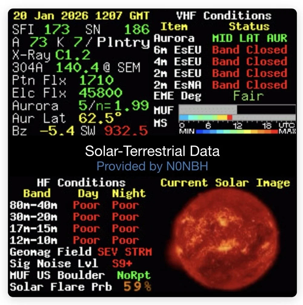
Yeah…about that… There seems to be a major solar storm coming in and has been since the previous day. This is a big deal as you can see from the report. It has shut down radio for most operations. I did call CQ for a while and at one point I heard WY7EE calling CQ but he couldn't hear me. Figures. I did turn up on the RBN so the signal was getting out to some degree in the evening. That was kinda awesome to see as well. I know I have signal going out too as the wattmeter is showing 40 watts forward power. (Remember I de-tune my Scouts to pull some load off the finals since they are getting old and I don’t relish the though of having to replace them for a 10 watt boost in power output) 40 watts will do just as well as 50 from what I have seen in the past… anyway.
The next day we had the storm to start fading out a little and I loaded up the webSDR on my computer and listened for my radio on the Northern Utah listening post. Once the time was late enough, I started hearing my signal on the webSDR! I recorded it and posted it to my YouTube channel as a short if you want to go listen to what I could hear. This is the link.
Link to video about 60 meter signal
Like I said, I am going to revisit the band pass filter for the IF again when I get back into town. I think that can be improved a lot. (my current design is too broad banded in the pass band to make me happy, I want to clean that up some more.) I will write that up when I get the chance to work on it—read Part 4 for the IF filter redesign. Thanks for following along on this little adventure and I hope to hear you on the air at some point. Maybe you will work me on 60 meters with my Scout…maybe…
73 and get out there!
All four parts are here:
- Part 1: Initial Conversion and Filter Design
- Part 2: Crystal Selection and Mixer Circuits
- Part 3: Field Testing and Troubleshooting
- Part 4: IF Filter Redesign (this post)
You can help support this website by using these Amazon Affiliate Links:
QRP/Portable Radios:
Antennas & Tuning:
CW Equipment:
Power & Accessories:
Organization & Transport:
BONUS ITEMS
WK4DS
David