![Building a 60m Band Module for Ten-Tec Scout 555: Crystal Selection & Filter Design [Part 2]](https://images.squarespace-cdn.com/content/v1/5d17806ce65eba00011667cb/1768486316134-5KK47YMDB3P45BK25B4N/IMG_1141.jpg)
Building a 60m Band Module for Ten-Tec Scout 555: Crystal Selection & Filter Design [Part 2]
I figured the the mixer’s bandpass filter would be the same as the IF filter but turn’s out I was wrong here. I looked at the existing part values on the chart for 40 meters and 80 meters (remember that part about not having a formal education in this stuff?) and simply decided that the inductors were again too big and I needed them to have a slightly lower value instead.
Well, if this is the first post of my blog you have found about the 60 meter band module, please goto this link and read the first part or a lot of stuff is not going to make sense…haha.
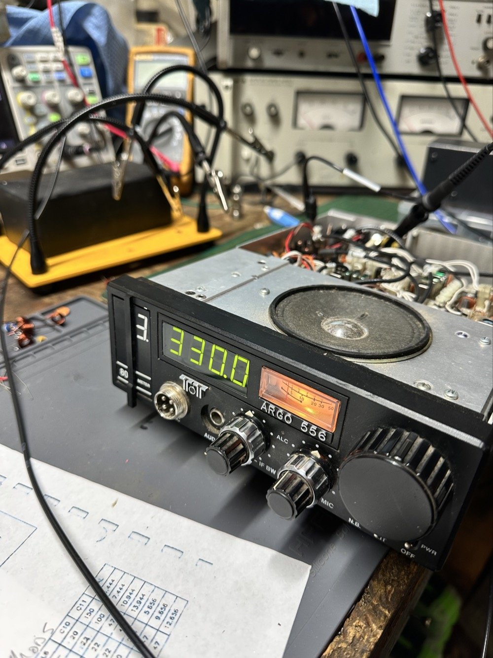
The donor about to undergo surgery to become a 60 meter band module.
As you know from last week, I was able to get all the filters updated except the output bandpass filter for the mixer and changing the crystal, so let’s get into that today.
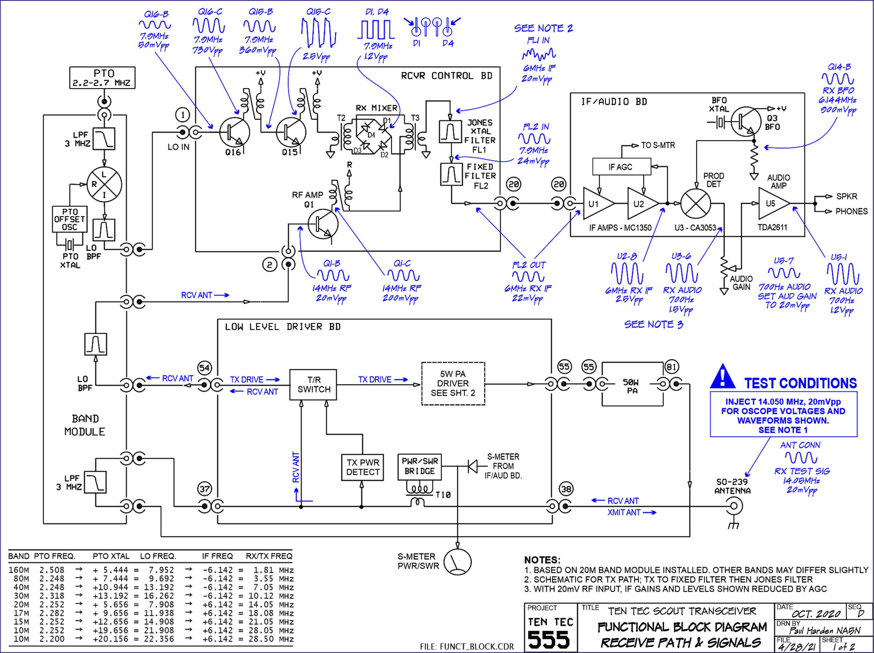
I figured the the mixer’s bandpass filter would be the same as the IF filter but turn’s out I was wrong here. I looked at the existing part values on the chart for 40 meters and 80 meters (remember that part about not having a formal education in this stuff?) and simply decided that the inductors were again too big and I needed them to have a slightly lower value instead. This is where things get engineery..is that actually a word? It should be. I started by simply using an online calculator to figure the values for this filter based on the chart from NA5N’s Website and my own simple math of a mixed product of 11.442 mhz. It falls right in the middle of the 80 and 40 meter LO frequencies on his chart. So now I needed a crystal…
Luckily I didn’t need matched sets like when making a crystal ladder filter so I was able to find 9.218 mhz crystals on Digikey for reasonable money. The calculated crystal frequency I came up with was 9.242 mhz to land at 5.300 mhz. This radio will absolutely transmit out of band and it is the responsibility of the user to stay in legal band space so I figured this would cover the entirity of the 60 meter band. The NA5N chart shows the PTO minimum frequency is 2.2 mhz so that is where I started my math.
2.200 mhz (PTO min.)+9.218 mhz (PTO XTAL)=11.418 mhz (LO) - 6.142 mhz (IF) = 5.276 mhz
The entirety of the 60 meter band is from 5.3305 mhz to 5.405 mhz so this will work perfectly fine.
All this math starts to make sense when you look at the chart at the bottom of this page. That is why I keep linking it…haha. So I build out the band pass filter and install the new crystal when it comes in and … nothing… Well, it did something actually. It would not lock onto the frequency at all, it would attempt occasionally, but most of the time it would just scroll numbers on the display of the radio. It obviously was not working. I was sure I had built the filter right… (turns out I was dead wrong…again…I am starting to see a pattern here…haha).
As I would soon find out, I built the filter for the 40 meter IF by accident. At this point I had a lot of numbers floating around in my head and scribbled on various pages laying around the bench and one was where I had done some of the math around the 40 meter circuit for some reason and I inadvertently used those numbers to make the inductors with. Couple this with a trip out of town for a week and you will see where I lost my train of thought. Once I returned from the trip I had just two days before leaving again to see what I could figure out.
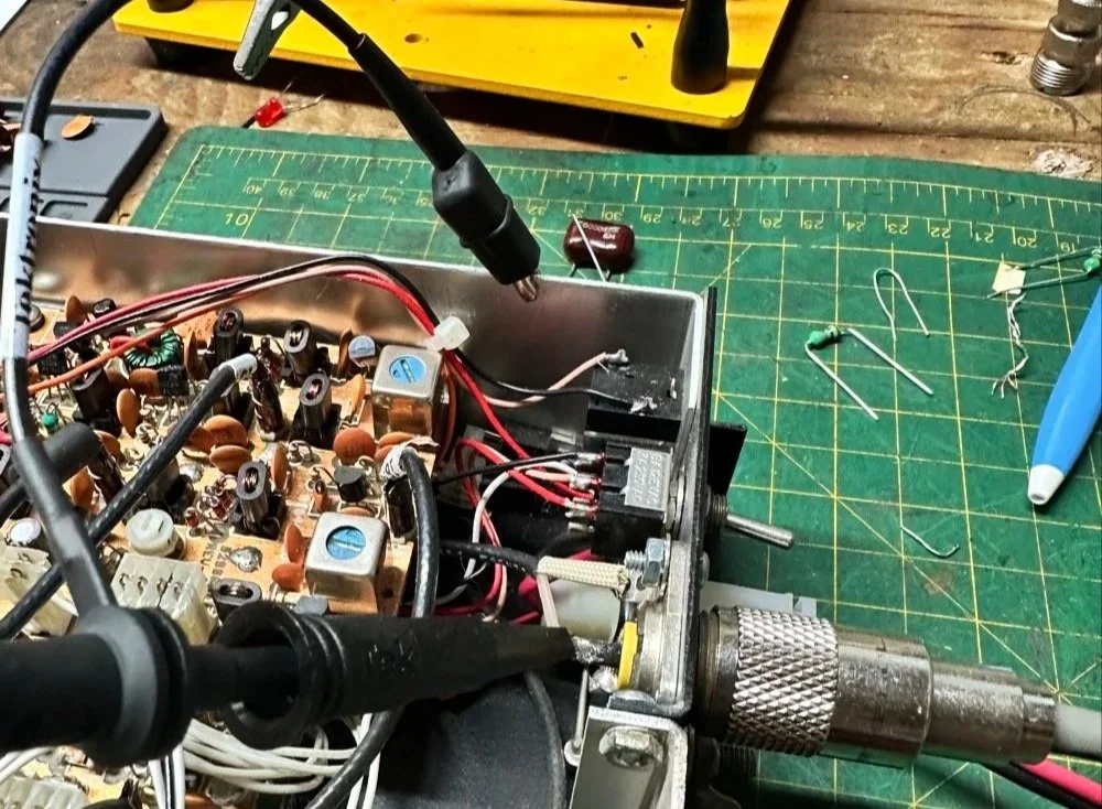
Well, this is what I figured out.
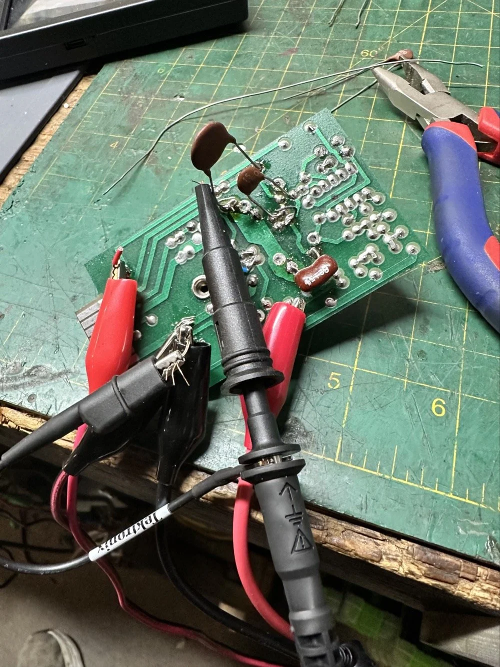
What you see above is a frustration point to be honest. I studied the print long enough to realize I could bring the circuit to life if I had a signal generator and a power supply. To get this to work I soldered several small scrap clippings from component leads to the board in strategic places to be able to connect leads for various devices and you get what you see above. I immediately went down a rabbit hole on signal generators and ended up with a UNI-T UTG962E and it arrived THE DAY BEFORE WE LEFT ON OUR TRIP. I get it going and power up the circuit with the 10 VDC bus and then inject a 2.2 mhz signal from the brand spanking new signal generator into the line (simulating the PTO) to see what I would get at the output… well… nothing. I checked the crystal and I had a clean 9.218 mhz signal at about 700mV going into the mixer chip but my 2.2 mhz injected signal was 50mV (the signal level based solely on the output shown on the block diagram going into the receiver control board as the data sheet for the chip I found didn’t show a signal level threshold that I could find.). This was obviously too low and I started turning up the signal generator and nothing happened at first. I was at 700mV of signal level coming out of the generator and I was getting nothing at the output of my filter. So I start walking it back to the output of the generator. I didn’t have anything at the output of the mixer chip as it turned out, so I check the inputs to the chip on the chip directly and the PTO input was almost non-existent. Turns out that the output impedance of the signal generator and the input impedance of the low pass filter for the mixer chip on the board must be different as it was dropping the level pretty dramatically. (This is something else I have learned while doing this project, you have to observe the impedance between stages or it wont work. ) So what do I do to solve for this? (Remember again I have almost no formal education in this area of expertise) I simply put the scope on the output of the mixer IC itself and slowly start turning up the 2.3 mhz amplitude till Eureka! The mixer sprang to life and I had a product!
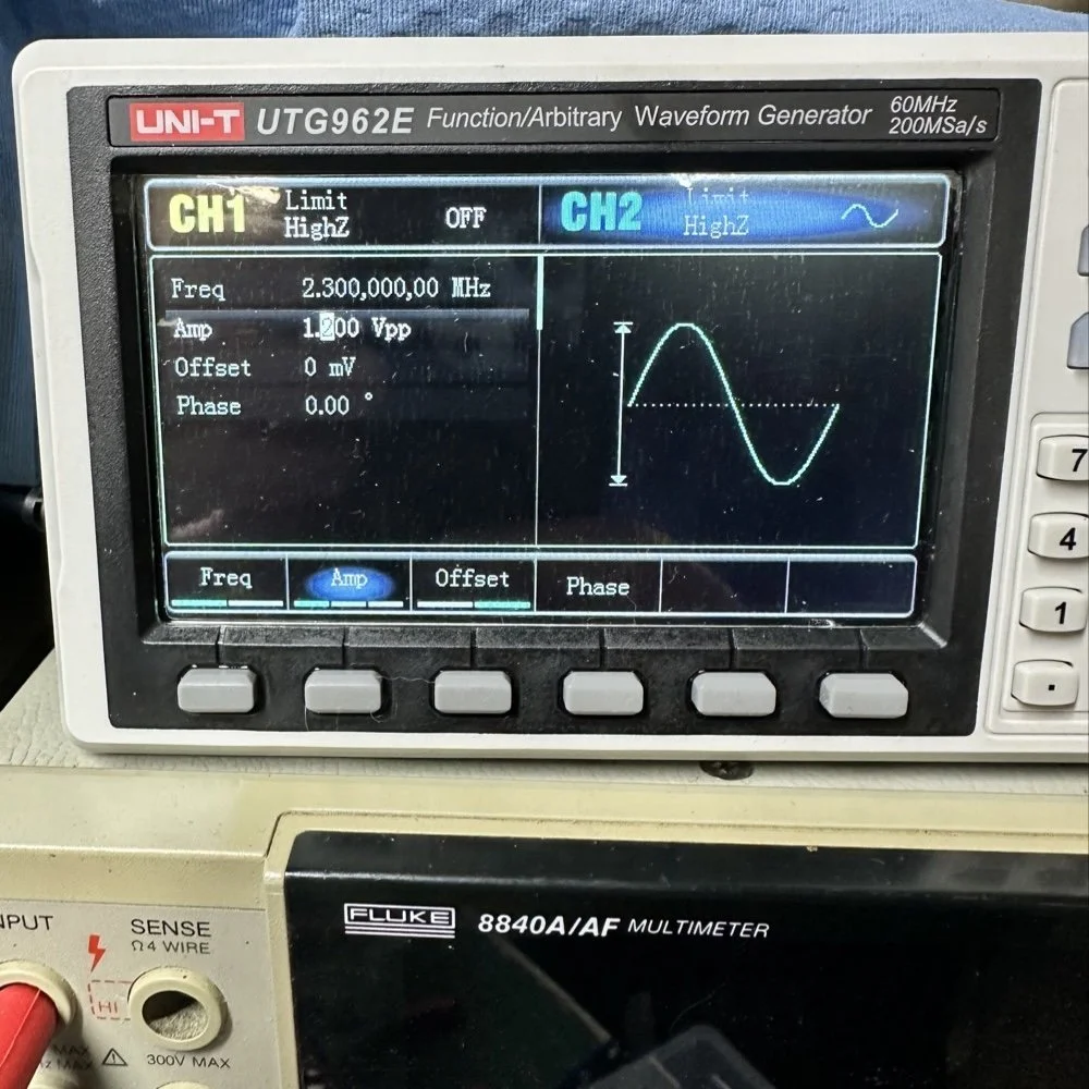
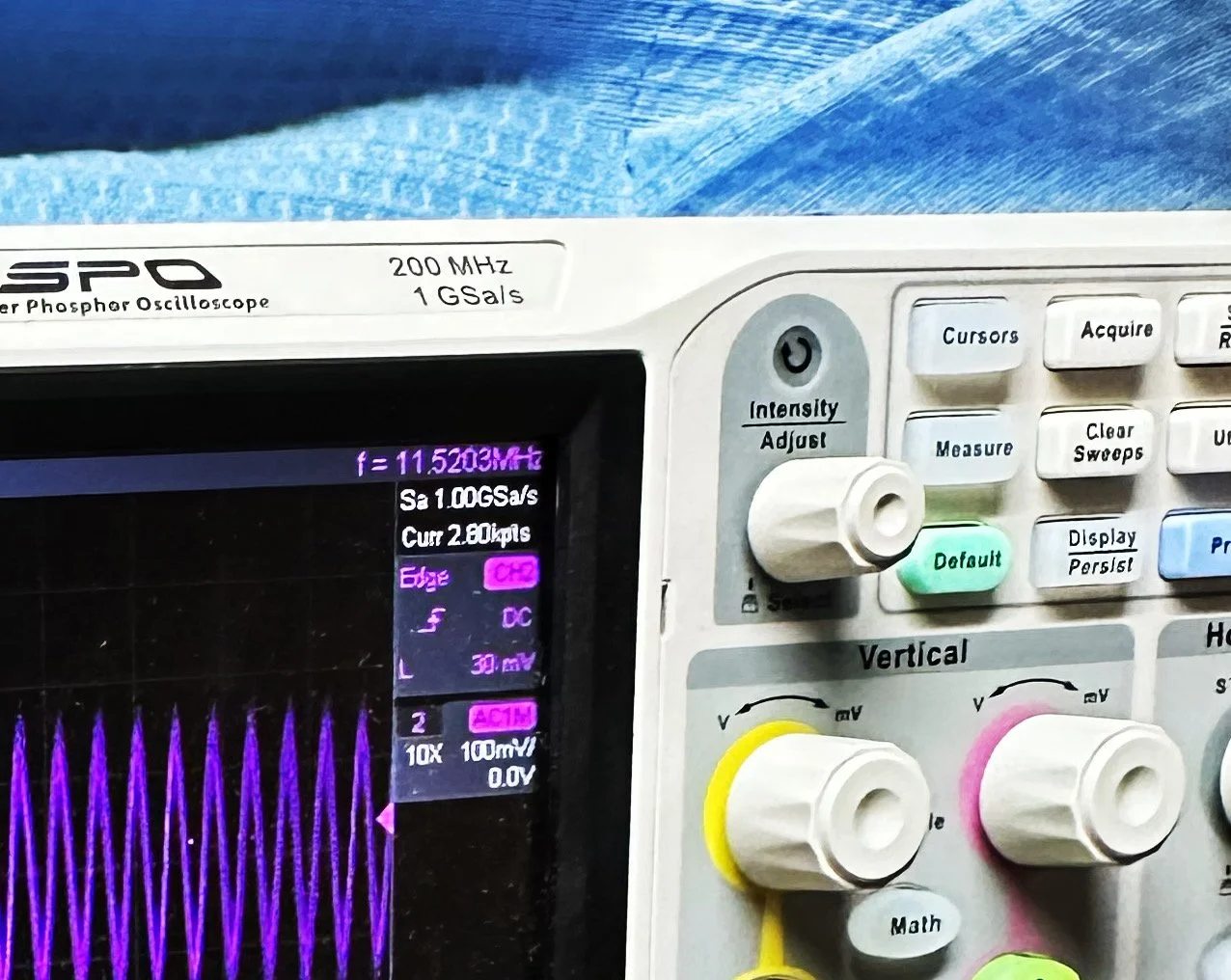
Note: I am using a different value here for the PTO reference signal because I didn’t notice that I had changed it till I got the mixer working. But it is fine as the PTO operates from 2.2 mhz up to about 2.7 mhz anyway. The key was getting the bottom of the mixed product below 11.425 mhz when the PTO is at minimum. This will allow tuning through the 60 meter band. But this is why the number in the photo below is 11.520 mhz and not 11.425 mhz.
Now that I have a signal coming out of the mixer IC, I need to see what it going to the receiver control board. You see on the signal path drawing from the NA5N site that he states it should be 50 mV or so there. Well I had nothing coming out of the band module at all. I start looking at the filter and this is when I figure out the filter is all wrong. Back to the drawing board again. I take the week long break and during this time away I dwell on what I had learned and spend even more time trying to learn how this bizarre filter works. It looks somewhat like a regular band pass filter but there are elements that don’t make sense to me. I spent a considerable amount of time studying this problem and decided to order some inductors and when I get back I could replace my home brew ones and see if I had done something wrong there.
Fast forward a week and I went home and had about 5 hours total to figure the whole thing out or it would wait yet another week… I start by replacing the two home brew inductors with two 2.2uH inductors from the variety kit I ordered. Still didn’t work, so there must be something wrong with the capacitors too. All of the caps at this time were class 2 capacitors so that would turn into a problem as they warmed up, but this thing was not working even when it was cold, so the values were wrong is all I could figure. The most logical thing was to strip them all out and start over. I had now gotten my hands on some NPO caps too, this allowed me to build out the filter completely with the correct rating capacitors thereby giving me the confidence that once it is working, it will hold value.
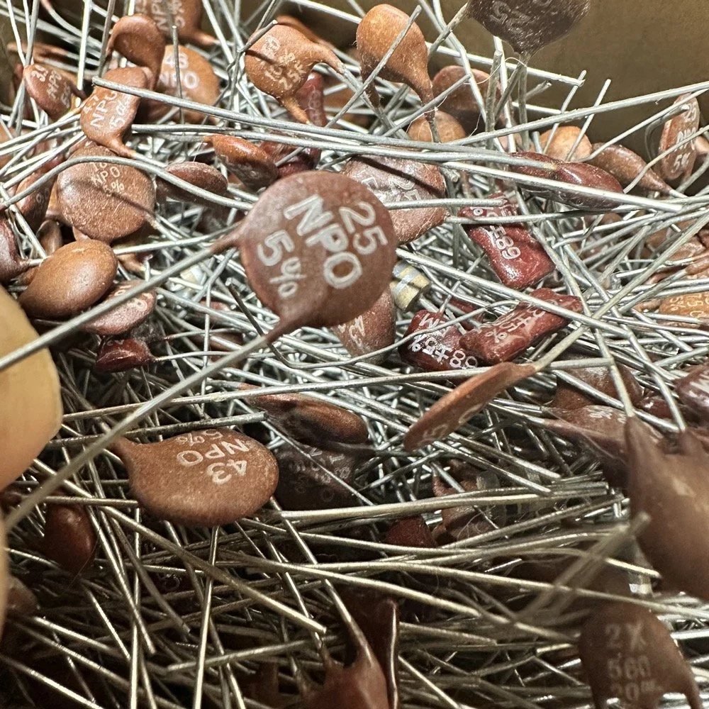
My first batch that I bought was a literal double handful of random NPO capacitors (and a few other ratings mixed in for fun) thrown into a box from eBay. I knew what I was getting so I also picked up some divider boxes to sort them when I got time. Now they are all sorted and I know where to find what when I need it. Of course, I don’t have every conceivable size to choose from but I do have a large assortment and can get by with most projects with what I have. Things like this are what I wished I had learned in trade school… I guess I should have chosen college instead…you know what they say about hindsight though...
The photo of the board above that shows all the leads connecting to temporary test points I soldered to the board has these capacitors on it. They are temporarily soldered on as I am experimenting with various values in different locations to see what will get me to where I need to go.
I tried to use the online calculators but this filter doesn’t fit into any of those models and all the outputs from those tools were not working for me. It looks like the coupling capacitors are also used to also limit the signal level from stage to stage as well. Correct me if I am wrong in this assumption, but tiny little 5 and 8 pF capacitors are not letting a lot of energy through them, even at HF frequencies and there are two in this filter circuit. I can only assume that they are also using these to match impedance as well or a larger value would couple the stages with more signal. Anyway, I was stumped and asking the internet for help is literally begging to be slandered and chastised for being stupid, so I didn’t even bother with that option. That only left experimentation and experimentation is what I did. I put all sorts of outlandish caps in this filter and found success doing it this way. It took me a few hours, not gonna lie, knowing how to calculate these sorts of things would have been immeasurably easier, but I was able to get the signal on the output trace of the band module and it had decent signal level too! Honestly, I am going to revisit the output signal level when I get back home (I may have already done it by the time this goes live on my site) and see if I can attenuate the level somewhat as it is higher than what the base of Q16 on the receiver control board shows in NA5N’s pictogram.
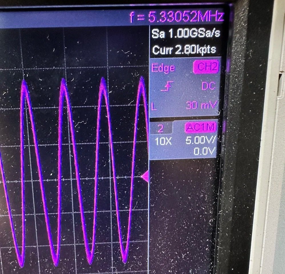
What you are seeing above is the output of one of my Argo 556 radios that I used as a test bed to check the signal levels and such to see what was going on with it. As you can see I simply connected to the output of the radio and looked at the signal going into a 50 ohm dummy load. I did the math (I know, I know… this has not been a great idea for me in this blog post… lol) and it comes out to about 1.8 watts and not 5 watts for this radio (I have not attempted to turn up the transmit power on this unit yet either so it might simply be turned down or something like that. Let me know if my math is wrong here, but 27 volts peak to peak and 50 ohms should give me a power level of 1.82 watts at the antenna connector?
Power= peak voltage (13.5volts) divided by the square root of 2 and then that is divided by resistance.
All that aside, I took the newly minted 60 meter band module up to the shack and setup a Scout 555 and connected it to my home antenna. Tuned the antenna up and started looking for a QSO. I promptly found one and had a short ragchew with VE3USP in Ontario despite some QSB along the way. It works perfectly too. I do have to dial up 600 hz to be on frequency as it is a Scout 555 after all, but that is not a problem!
So I am not completely finished with this module as of yet. I still want to look at that output filter from the mixer and tune it some more. It is close, but it is not right as the signal level is too high. I found I missed a couple of capacitors when I dismantled it to clean it that need to be NPO capacitors instead of what I currently have in place as well. I would also like to improve upon my terrible painting skills if I could figure out a way to do it…lol Seems acrylic craft paint might not be the best solution here…
Next week we get into what happened when I took it to a POTA park… hint: I brought it back home and got inside a little more to fine tune it…. I discuss this next week and show you what I came up with for the mixer output filter ultimately.
73
WK4DS - David