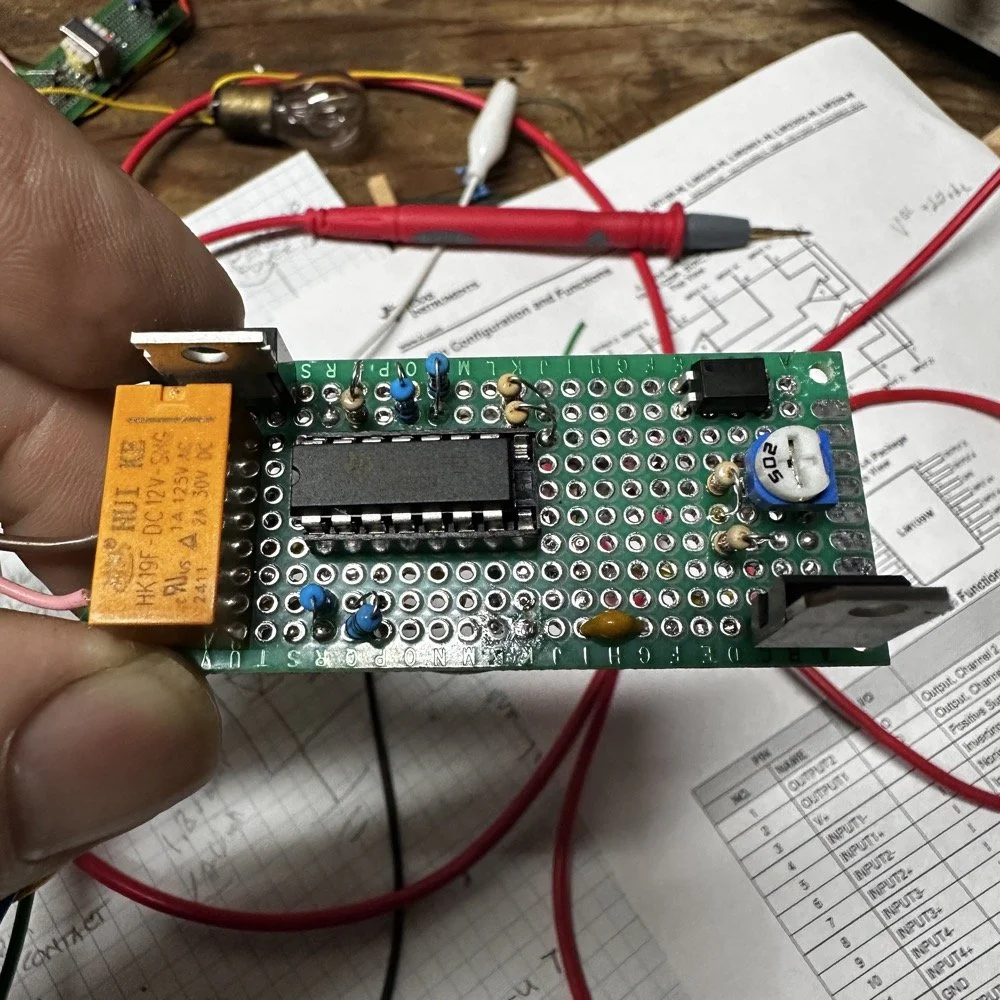
I finally finished my LiFePO4 Solar Battery Monitor project…
When I tell you that I have been working on this one for a while, I mean it. This project has been going on for several months. I drew countless pages in my pocket notebook about how to solve this problem. It just would not work. You see, it is more complicated than you think it is. It is also as simple as you think it is too…
When I tell you that I have been working on this one for a while, I mean it. This project has been going on for several months. I drew countless pages in my pocket notebook about how to solve this problem. It just would not work. You see, it is more complicated than you think it is. It is also as simple as you think it is too…
The Problem with LiFePO4 batteries and Solar Charge Controllers
Here is the plan, I need to add a small circuit that will watch the battery level and determine whether or not to enable the switch to run solar power directly to the house during the day. This needs to be automatic and needs to be adjustable so I can fine tune it once installed to match the battery system I am using.
The problem is this, if I leave the current system in play all the time, the new lithium iron phosphate batteries will shut down and go to almost zero volts in protection mode. This is the internal battery management system protecting the cells. This only happens when I have several overcast days in a row. You see, the solar “daytime” detector will still enable the solar to the house as long as the AC inverters will power on. The problem is that now the voltage on the battery terminals is almost zero if that happens. The solar panel charge controller wont “cut in” and deliver current to the batteries until it sees a battery connected. The batteries cant charge because the charge controller wont turn on to charge them. SO I have to “jump” the system off with another battery from the other bank. I literally have to take another battery loose from the other set and slide it over to this set and touch the cables to the dead cells to start the system. Once the charge controller sees the voltage, it comes online and the system will start to recover.
This wasn’t a problem with the old lead acid wet cells as they would still have voltage in them when they would get too low to power the inverters. So the next day they would start charging. Not so with the LiFePO4 batteries. They will leave you high and dry with this type of system.

How to come up with ideas to solve your electronics project problems
I probably have 20 pages in my notebook that look like these. Sometimes it is good to simply write down your ideas. Even if those ideas turn out to not be right, you should still write them down so you can analyze them to learn from them. This is some of that writing. Also I was writing in a secret Gen X code…haha. I would think of an idea and just get out the notebook and draw a simple circuit and write down what I was thinking. This way I could go back to it later and not forget what I had thought of already. Another thing that helps is to read back over your notes occasionally so you don’t reinvent the same idea more than once. Yet another reason is that after the idea has soaked a few days (or even weeks) when you see it later, the solution might just jump off the page. Sometimes it just takes a while to get the whole concept put together.
I really wanted to use photo sensing elements in the design (as you see in the drawing above) and I finally did… The thing is that I didn’t need to add any, the photo sensor is already in place… I ended up using the daylight solar detection cell…The same solar panel that powers up the relay that switches on the inverters and then turns on the relays for the house to run on solar during the day automatically. This circuit I built will only need a few milli-amps of current to pull in the little solder on board relay that I used. It will only need this current it the batteries are also under the voltage threshold and that is above the cut off level. The nice thing is that as you see below, I was thinking I needed a timer to carry the whole day when I figured out that if I use the solar panel like I am using it, then the sunlight will keep it turned off anyway…even if it charges above that level during the day.. It will simply engage the SCR which will stay on till the solar panel shuts it off at the end of the day and then the system will automatically stay off through the night till the next morning when the system has been reset and it starts all over again.

The circuit concepts for a LiFePO4 Solar Battery Monitor
I started out trying to use NAND gates as I had some of those left over from the other battery monitor project. This turns out to be doable. The problem is that it starts to rapidly get overly complicated and you have to work in voltages that are where the gate operates at. This is where things got tough for the NAND gate. The gate has a threshold where it trips from one state to the other and you have to tune the circuit to work in the region. It is really consistent fortunately. This makes them work for this. I did some online searching and found that Texas Instruments also makes the LM339N comparator chip. This literally takes an analog signal (a voltage level) and compared it to another analog signal (another voltage) and if A is higher than B it flips states, and if B is higher than A then it flips the other way. This is literally the answer to my problems!
The thing that makes it special is that you don’t have to tune the circuit to the trip point of the comparator but rather you choose the level it trips at and compare to that. Brilliant and so much simpler!
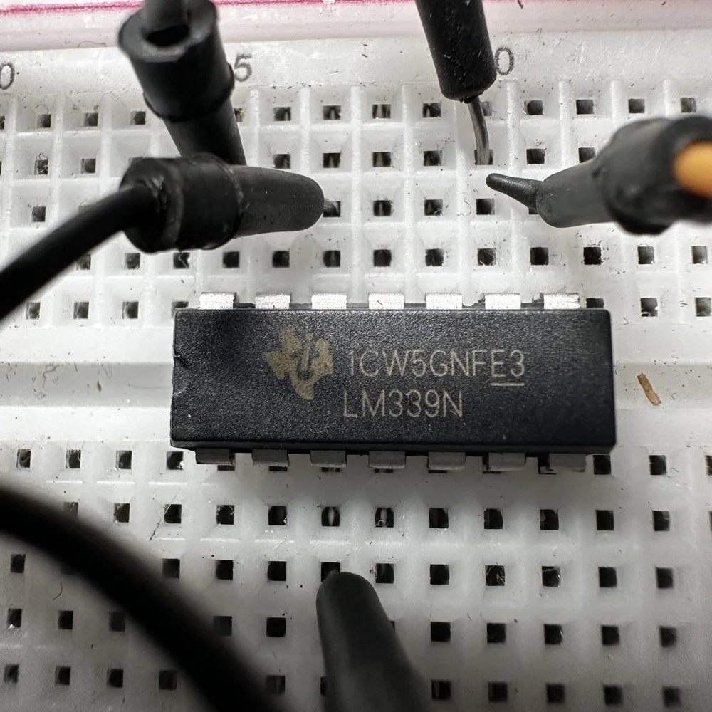
I promptly ordered some chips and went to work playing with them. The chips I prefer are what is known as through hole style DIP packages. I still build on perf-boards and have not gotten to where I can really work with surface mount stuff yet so I still use the old through hole parts for my builds. This is supposed to be a genuine Texas Instruments part, but these days, you really don’t know unless you buy from Mouser or Digi-key… These came from Amazon, so who knows…haha. I do know that they work as advertised for the application that I wanted them for, so it is all good right now.
I had to come up with a way to detect the voltage and then also compare that voltage in the same circuit against two inputs. After a little thinking, I came away with a regulated power supply adjusted down to some level below the supply and then the other input is run through a simple resistive voltage divider. The LM317, while antiquated, still works fine. It doesn’t hurt that I have a drawer full of them too. I am moving to the newer and better LM350T, but for this one, it is the good ole 317. So what I did was this. I used my adjustable power supply to set the “supply” to my desired cutoff voltage of just over 24 volts. Then I simply turned up the adjustment on the 317 till the state flipped on the LM339. This had to be the easiest calibration sequence in the history of the world… haha. I bought quad packages because they were in stock. The smarter play would have been to get the dual packages instead, but you use what you can get and I didn’t want to wait.
Below shows how they are connected internally and it really is that simple.
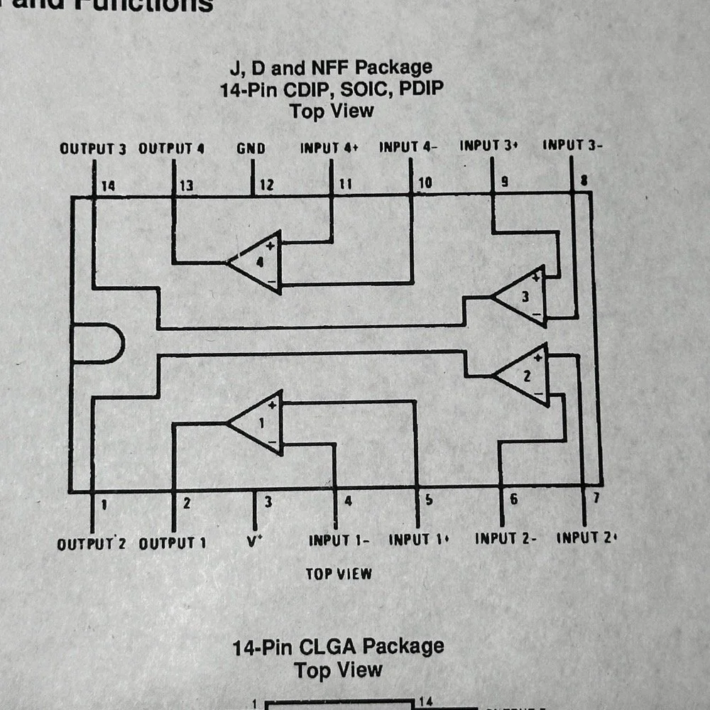
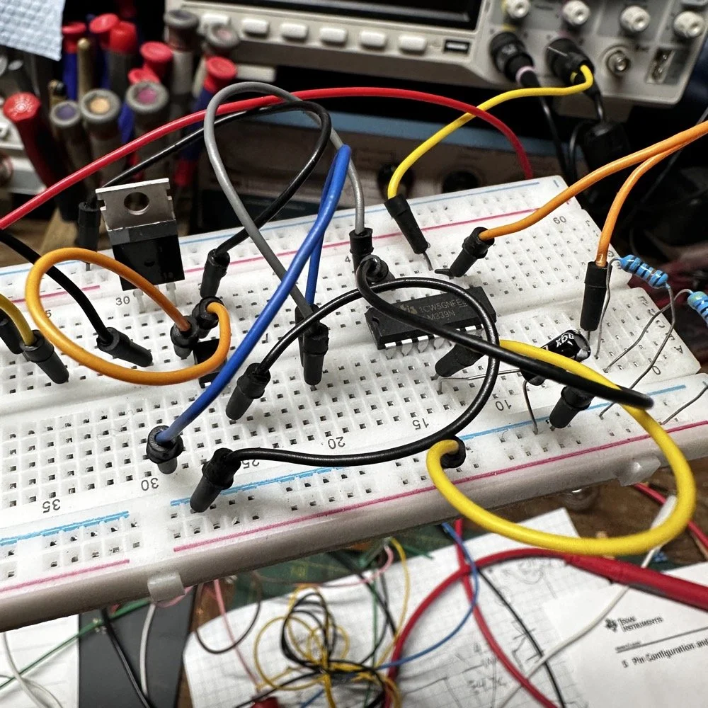
The LM339N works by comparing two analog signals in what they call the ( input - ) and the ( input +). These do not have to be positive and negative, but rather they are simply two levels that are compared. It isn’t as complicated as I was trying to make it at all. The first thing I did was put a circuit together on the bread board and play with how it works to see if I could get it to do what I wanted it to do. Turns out it would work just fine after I figured out a few things like the fact that the SCR needs to be on the ground side of a relay if you are using it to latch a relay in the “on” state. If you put it on the power side, it acts like a switch and turns the relay on and off as the voltage moves above and below the threshold. Hold that thought…
I did some simple ohms law math for the current draw needed to pull the SCR gate in and to fire the opto isolator, so these devices would work and that is what those 1330 ohm resistors are about on the bread board. By the time I had taken this photo though, some of the parts had already been pulled to move them to the more permanent solution… perf board.
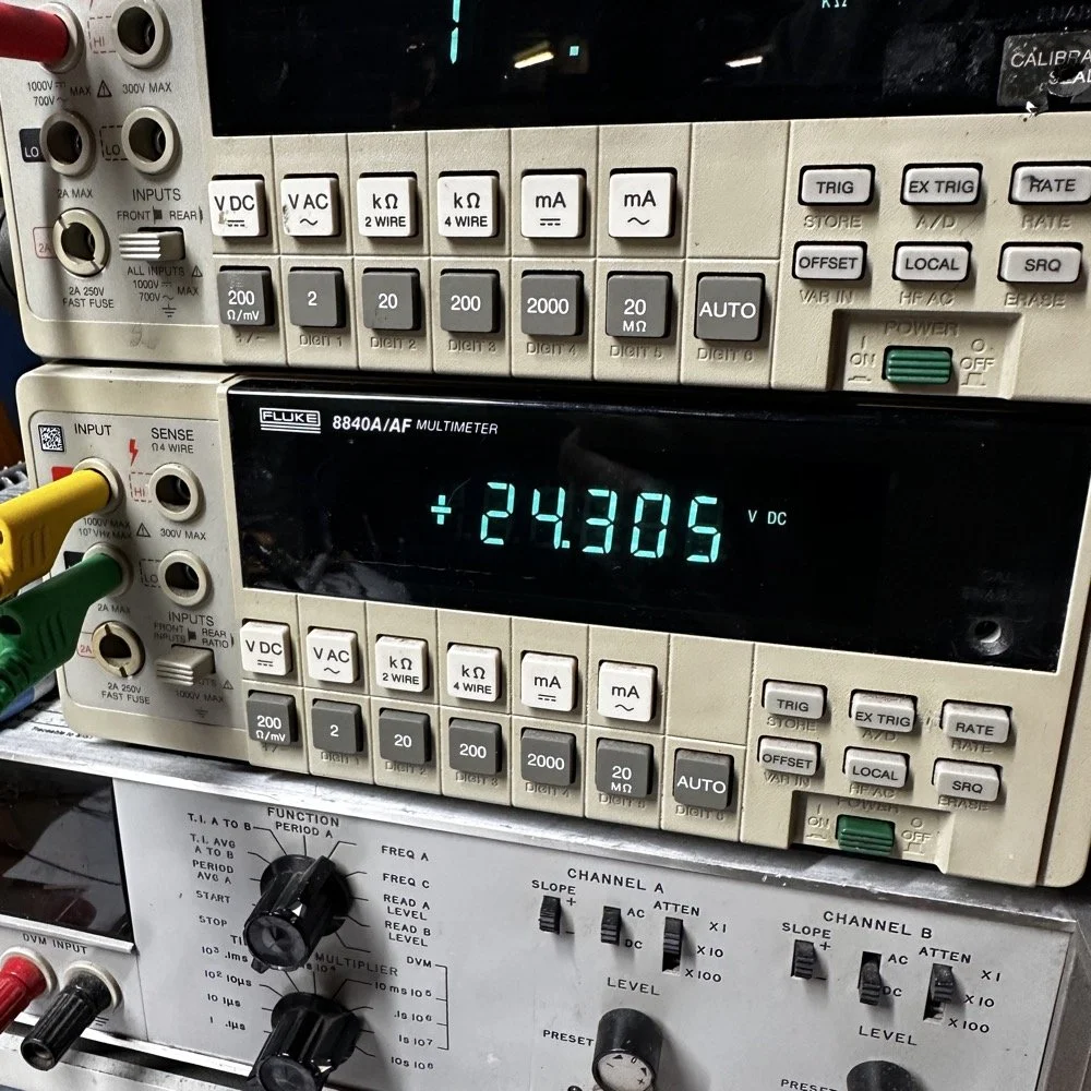
I set the trip point for now to 24.305vdc and will see if that will work when I get it installed on the system. You can see that I love these old Fluke 8840 meters as I now have two of them. One is this A/AF (Army/Air Force) variant and the other is the standard commercial variant. They are both incredible bench meters as well as a few others that I have on the bench. I wanted an Agilent or Keithley meter, but they are WAY more costly and I dont do work that is that important at this time… haha.
Building the LiFePO4 Solar Battery Monitor Circuit
Below you can see that the perf board design is truly just “come as you are” construction. You just place parts where they will fit and wire them accordingly.
I seem to always run into problems with this though as the pin outs are reversed when the board is flipped… remember what I was saying earlier about wiring the SCR backwards? Yep, I did that while LOOKING AT THE DRAWING I MADE SO I WOULDN’T DO IT!!! That is how easy it is the get things mixed up when building these kinds of circuits and remember, mine was simple!

The top of the board looks great…it is when you turn it over that you see the real mad scientist. The bottom looks like something out of a horror movie! I tried to keep all the components on one side and the wire on the other, but it was just going to be too much work to remove the other resistor and put this one in its place. Haha. So I simply soldered it in parallel with the other one. The other resistor was a really high value so it changed the circuit very little anyway. So I have one part on the back… such is life.
What amazes me is that this circuit started up and worked perfectly (once I moved the SCR to the correct side of the relay). Seriously, that mess actually worked like it is supposed to somehow.
Now, this is not the first iteration of this board. That is partly why the wiring looks as rough as it does. I did attempt to use a transistor to start with as a buffer between the comparator and the SCR but it would not work reliably. Enter the opto isolator. This little gem solves that problem in style. I have grown to love these for buffers between two circuits. Simple to use and reliable.
Using the opto isolator keeps the two voltages separated so that there is no cross contamination.
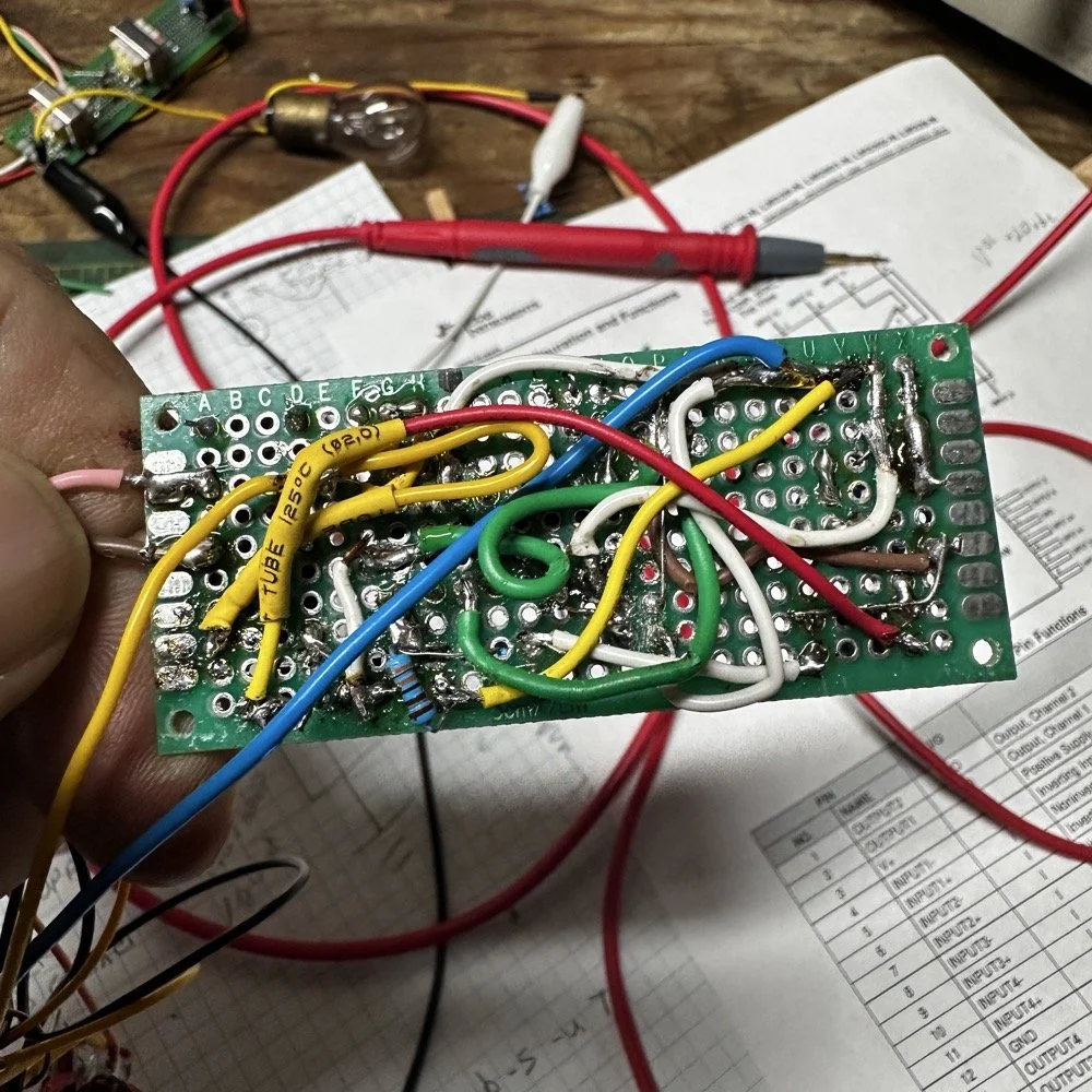

You can see here that page on the upper right is the drawing I finally settled on. This one is the one that worked by pulling the gate to ground when the comparator output is high.
There is no need for an on delay timer since it is constantly looking at the battery level and generating an output relative to that level. When the sun comes up, it will power up the SCR side of the circuit and set the relay based on what the opto isolator is doing when it comes on.
Comparator output is high? Then the SCR gate is pulled to ground via the output from the opto isolator and the SCR stays off. Comparator output flips low, then the opto isolator shuts down and the gate of the scr gets sufficient voltage and current to fire and latch.
Finally, testing the comparator circuit in the actual system!
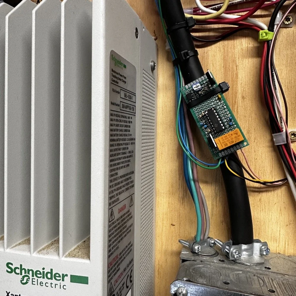
Here is my “temporarily” permanent installation in the solar power room. I will run it a while and if it works like I want, I will move it into a project box. Initial trials so far look promising. This just might be the answer I was looking for.
Do you experiment with little circuits to solve simple little problems around your house?
Support this website by using these affiliate links to shop on Amazon:
My Soldering Station: https://link.amazon/B01N4zQYx
Solder: https://link.amazon/B003Fyezg
Solder Wick: https://link.amazon/B0cSEsTQN
Hook Up Wire: https://link.amazon/B0i7fzwLM
Long Reach Needle Nose Pliers: https://link.amazon/B01Cifgx5
Perf Board: https://link.amazon/B0fpuDPOt
TI LM339N Ships: https://link.amazon/B00gFZr2q
OWON 3 in 1 Meter:https://link.amazon/B0gGsVWeH
Thanks and I hope to hear your stories soon!
David

DIY Low Battery Alarm Circuit: Discrete Component Design with SCR Latch & LED Display
You see, I love discreet component projects and the use of transistors in those builds. No this is not to say that I am against things like Arduinos and Raspberry Pi SBCs. Quite the opposite in fact, I love them when the application can actually benefit from one of those devices being employed. This project could have used one of these, to be fair, but it would have been grotesque overkill to use an SBC on a project like this. (An “SBC” is a Single Board Computer and is essentially the whole system, albeit a little weaker than bigger machines, on a single circuit board)
I had a problem to solve. The VERY crudly drawn schematic I made in KiCad is how I solved it.

You see, I love discreet component projects and the use of transistors in those builds. No this is not to say that I am against things like Arduinos and Raspberry Pi SBCs. Quite the opposite in fact, I love them when the application can actually benefit from one of those devices being employed. This project could have used one of these, to be fair, but it would have been grotesque overkill to use an SBC on a project like this. (An “SBC” is a Single Board Computer and is essentially the whole system, albeit a little weaker than bigger machines, on a single circuit board)
I opted to see if I could come up with a way to use discreet components to build something that fit the following criteria:
simple design
small footprint
no programming required
doesn’t drain the batteries excessively
works on 12 vdc power
can detect when a 4 D cell array weakens to 5.4vdc
fires an alarm that latches on when triggered
is noticable and easy to notice when triggered
Some of these parameters came about after the fact as I would build something on the bread board and try it and then figure out that I needed something else to make it work like I wanted it to.
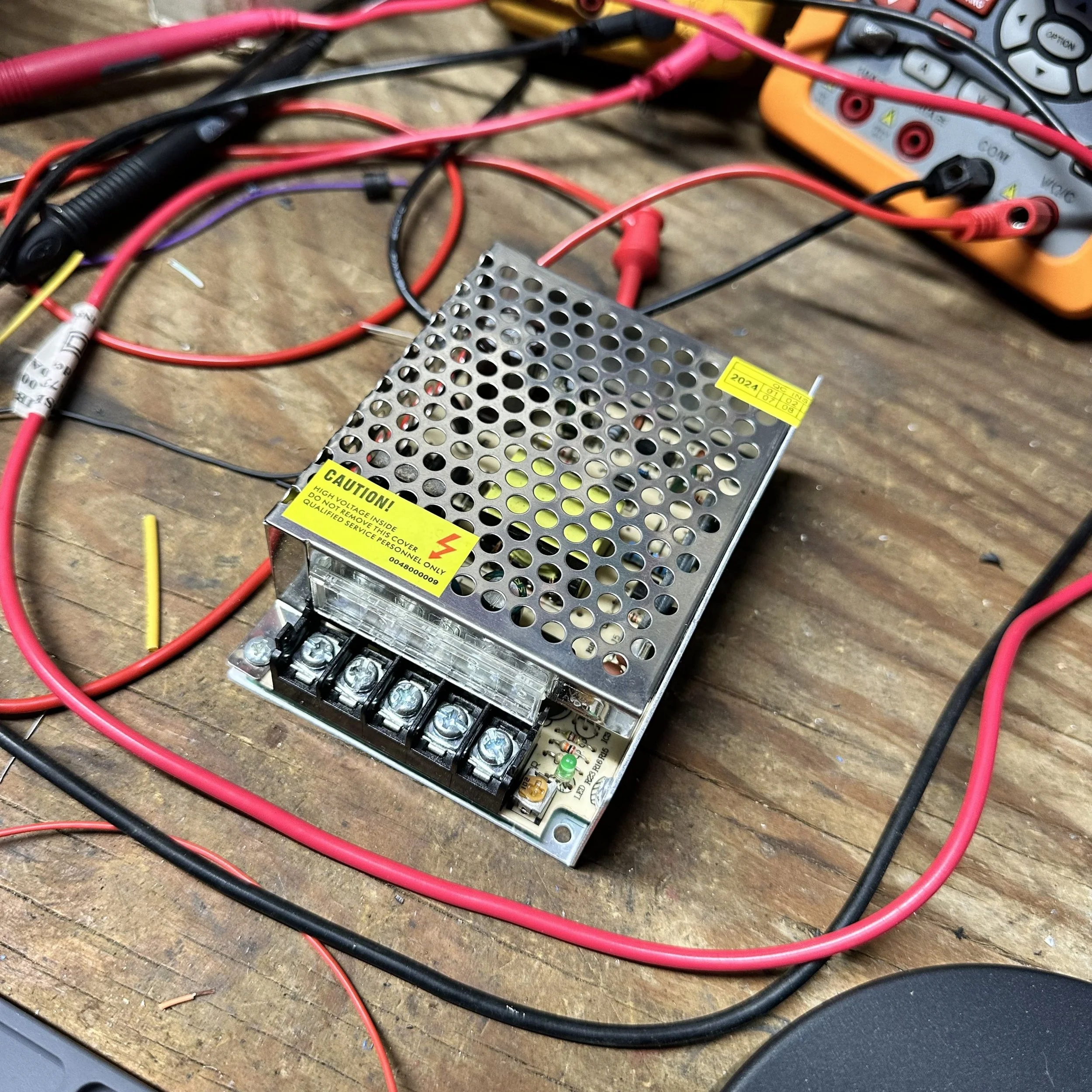
All good things start with a great power source. This is no different, this is a adjustable 12 vdc power supply. These are super stable and relatively cheap too. I don’t remember the price for this one, but it was very reasonable. This is also severely overkill for this project too. This whole project only draws about an amp max. Probably closer to 1/2 amp to be honest with the lion’s share of that being the LED display draw which is a little over 300mA of the whole thing. Regardless, this is what I bought so I used them. At least I have some room should I want to add something else later that uses 12vdc power…After making a few mistakes in getting some measurements by using one of my bench supplies, I realized I could simply power this one up and use it to do the tuning and then simply install it in the machine and use it to power the circuit too, this way there was no discrepancy in voltage and it worked like a charm.
Below is not the circuit I made for this project from but another one that I will be writing about. The point of this photo is to show you what I use to get my ideas out of my head. 1/4” grid graph paper is my favorite for this kind of work. It allows me to draw to scale (if I want) and it is easy on my eyes for some reason too. Can you figure out what the chip is that is in the below circuit by just looking at the surrounding circuitry? I bet you can if you do much discreet component building.
A quick disclaimer here, I use the term discreet component build pretty loosely here. The definition technically doesn’t involve integrated circuits, but I include any device that doesn’t require a program to make it work… That is why this project, in my opinion, is a discreet build even though it has a quad NAND gate chip in the middle of it as well as an opto-isolator package…
With that out of the way, let’s get to the theory of operation and why I did it like I did.

As you can see the board below, it meets the first two criteria right away. It is small and simple. The third criteria of no programming is not immediately evident since it has a DIP package chip on the board, but upon simple inspection this is also evident. The other criteria comes from the design itself and it will show up a little later.
Lets just go through how it works right quick.
The voltage regulator is obvious, I am using it to make the 5VDC refernce voltage for input A as well as the Vcc for the gate chip.
To get the “trip” effect out of the gate, I make one input high all the time and the other is watching for the input to go low. I chose a NAND gate which is a AND logic function with an inverter on the output to simply reverse the state of the output. This is because, I need to see when the voltage goes low and not high. A NAND gate will give a low output when both inputs are high and a high output in the rest of the possible conditions.
When the voltage of the batteries go down to 90%, the voltage is 5.4VDC and with the voltage divider, the gate gets 2.08 volts at this point. This is the trigger point for the gate, anything less than this number and the input flips to low.
When this happens, the output of the gate goes high (5VDC) and then flows to the base of the NPN transistor to bias it, but there is a little trick here too. I added a 100K ohm resistor and a 100uF capacitor to this circuit to add a time delay to the base being biased on. What this does is allows the circuit time to power up and all the voltages to stabilize before this transistor is triggered, preventing false high outputs upon power up.
The transistor fires the photo diode side of the opto-isolator with a couple of resistors to control current and drop some of the voltage from the power rail since this is on the 12VDC part of the circuit.
The output of the opto-isolator is wired to the gate of the SCR package through a voltage dropping resistor with a small cap to absorb any voltage spikes that might come down this line.
The SCR is simply wired in series with the LEDs and acts as a simple latching relay in this application. This insures that if the battery voltage dips below the set point at any time during the work day, the display will turn on and stay on till the batteries are replaced and the machine is powered off…at least that is how the machine should be responded to when this condition exists…
i could have probably left the opto-isolator out and just used the transistor to directly control the SCR, but I wanted to play with the opto-isolator to be honest and see if I could make it work. HaHa.

I really love using perf board to build my projects. It is the lazy mans way of making a PCB and it is also the impatient man’s way as well. There is no waiting to get to see my project come to life when I use perf board on the contray should I have designed my circuit board in KiCad and sent off the gerber files to make them. First I would have to finish learning how to make the designs in KiCad, then I would have to wait to get the boards in… Plus I only need two of these boards as well, so I didn’t have to do all that design work for a circuit board for just two units… The perf board can be had from Amazon for very reasonable money and it comes with header pins as well as the screw terminals you see on this board for making outside connections to the circuit. That is the exact place I bought these boards from, they come in a kit of stuff for about 20$ if memory serves me on this.
Another tip I am giving away for free is below. I draw isometric views of some of the parts for reference when assebling them. This keeps me from wiring them up backwards…most of the time… I got one of these SCRs backwards out of the gate for some reason and the leakage current make the LEDs glow dimly but I could tell something was off so I checked and sure enough, the anode and cathode were backwards… So yeah, it can help to have that 3D view when wiring it up if the lead arrangement is odd like it is here. You can also see where I drew the layout of the opto-isolator as well with the components physical layout next to the pins for reference. This really helps with DIP packages…

I started out using a transistor to fire the LED array to signal the battery was low, but this turned out to be unreliable to start with. The LEDs would not latch on and could turn back off with a transistor controlling them. This is why I opted to use a SCR as once it is fired “on”, it will stay in the “on” condition till you power down the device. This did exactly what I wanted since it allowed me to pick up the signal immediately and on the first time it happens and it latches on so you cant miss it.
I next chose all the components based on their ability to operate on 12vdc power. This allowed me to use a simple 12 volt power supply to drive the circuit. To get the required trigger voltage for the NAND gate logic, I simply added a LM317 voltage regulator and tuned it to 5 volts (yes, I could have used a fixed 5 volt regulator, but I had 317s on hand so I used those instead.) Anyway, I needed the 5 volt power for the NAND gate as it can be run in three power modes and if you apply 12 volts to it then the trigger voltage could be greater than 6 volts which would make my whole project nullified from the outset. So running it at 5 volts means there is a tipping point when the input goes from being high to low and this turns out to be right at 2.080vdc. When the voltage goes below this value, the gate trips. This is where I would operate my battery detector then…but wait, my battery is 4 alkaline cells totaling 6.4vdc when fully charged, so how do I come up with 2.080volts? Well I thought about it for a while and settled on a simple resistive voltage divider. The trick is that the gate is looking for voltage and not much current at all. So I could used very high resistances and it would work fine. Values like 1.68 megaohms and 1.1 megaohms were what I initially came up with. this sum totaled a constant drain of 3.2 microamps. yeah…microamps… I couldn’t even measure it with my big fancy Fluke bench meters and had to resort to the Fluke 187 which has a micro amp selection on it to do this task. You would think something like the 8840 would also have it but it does not…
I wound up changing the circuit to include a 1 megaohm resistor and a 1 megaohm potientiometer in series for an adjustable trip point voltage divider instead of the 1.68M resistor. This worked really well and made setup so much easier. I was able to adjust the trip point to almost exactly 5.4 volts by doing this.
To put this kind of constant energy drain into perspective, if these batteries were to be drawn down as 1 watt continuously for a whole day, the comparison energy draw is 27 micro watts… yeah that is .000027 watts of draw. The ratio in time is this. 1 day at 1 watt is equal to 37,037 days to .000027watts to get the same energy transfer! That is over 101 YEARS to use ONE WATT of constant energy drain! I think I am good…

This Fluke 187 has a bad battery compartment due to corrosion, so I made up a simple voltage regulator circuit and cord for it and soldered this to the battery terminals so that it is now a bench meter and has worked in this role for years now flawlessly. Sometimes you have to make lemonade… Today that lemonade came in the form of a micro amp meter since my other two precision meters dont go that low on amp draw.

I made the display out of a project box and 30 LED diodes. A simple program for my CNC milling machine and I had the hole pattern for the LEDs located and ready to load out. I used the blue LEDs as they are brighter and trigger better than red in my experience with this project. I don’t think the color makes a difference since if this display comes on at all, it indicates it is time to replace the batteries before powering the machine down. I also decided to change the current draw on each one to half normal draw to about 10mA instead of the usual 20mA. I did this to lower heating of the display and to hopefully make the diodes last longer as I don’t want them to burn out if they are on for a few hours while we goto the store to get batteries. Also as you can see in the photo below, when you combine 30 LEDs into a small area, they cumulatively get bright anyway so it still shows up great.
Below is what the back of the LED readout looks like. I simply soldered all the current limiting resistors to the LEDs and then put heat shrink tubing on them to insulate them from one another. I checked the power dissipation for the resistors and they are all at 50% of rated capacity or less so I didn’t worry about the heat shrink insulating them thermally and just went with it.

When I started filling out my tinkering bench I wanted some really nice multi-meters to use on it. I started with the Fluke 8050A as I have always been intrigued by the push button design and the layout has this futuristic kind of look to it as well. Oh! …and they are quite accurate too…haha. Then the bug got me and I started looking on eBay at the 8840 meters. I stumbled upon someone who had a few of these surplus and I got it for reasonable money. This is the military variant as it is the 8840 A/AF (which just means it has specific things the military wanted in the spec sheet) but it is VERY accurate and does 4 wire ohm readings for low resistance circuits. I love these meters tremendously and use them all the time.
Also, you no longer have to worry about the display in the 8840 family getting dim either. People make new LED replacements that are plug n play and work great. They are on ebay and I play to pick one up for when my display starts getting a little dim as well.


Here is what the system looks like installed on the turning center. I mounted every thing out of the way of the main equipment and still had it located near the battery compartment for an easy reference. The circuit board s mounted with one screw and the screw is held in place with two nuts. One nut is tightened against the cabinet wall than the other is tightened against the back of the circuit board to make it a defacto standoff. Worked really well. I simply drilled a hole through part of the board that has no electrical parts on it and all was good.


The photo a few panels up shows the proximity to the battery compartment. I wanted it here so it would be a geo-physical alert as well. The batteries you have to replace are directly about the illuminated sign. It is not possible to power down the machine and miss this. They are right next to each other. You see, the way Fanuc controls of this era are built, they will not lose their memory as long as power is applied. So you simply replace the batteries before powering down the machine and you are good…as long as the power company doesn’t drop the ball right at that moment…haha
Help support this website by following these affiliate links when you shop at Amazon:
HDS272S Oscilloscope (My Favorite Portable Scope-Meter)
KAIWEETS Smart Multimeter (My meter I keep in the truck)
Kaisi Extra Large Soldering Mat
No Clean Soldering Flux (All flux needs to be cleaned off but I like this best)
I hope you enjoyed this little project and I will have more coming in the future!